EP1645760B1 - Lageranordnung - Google Patents
Lageranordnung Download PDFInfo
- Publication number
- EP1645760B1 EP1645760B1 EP05021644A EP05021644A EP1645760B1 EP 1645760 B1 EP1645760 B1 EP 1645760B1 EP 05021644 A EP05021644 A EP 05021644A EP 05021644 A EP05021644 A EP 05021644A EP 1645760 B1 EP1645760 B1 EP 1645760B1
- Authority
- EP
- European Patent Office
- Prior art keywords
- race
- sleeve
- resilient member
- bearing assembly
- ball
- Prior art date
- Legal status (The legal status is an assumption and is not a legal conclusion. Google has not performed a legal analysis and makes no representation as to the accuracy of the status listed.)
- Expired - Lifetime
Links
Images


Classifications
-
- F—MECHANICAL ENGINEERING; LIGHTING; HEATING; WEAPONS; BLASTING
- F16—ENGINEERING ELEMENTS AND UNITS; GENERAL MEASURES FOR PRODUCING AND MAINTAINING EFFECTIVE FUNCTIONING OF MACHINES OR INSTALLATIONS; THERMAL INSULATION IN GENERAL
- F16C—SHAFTS; FLEXIBLE SHAFTS; ELEMENTS OR CRANKSHAFT MECHANISMS; ROTARY BODIES OTHER THAN GEARING ELEMENTS; BEARINGS
- F16C11/00—Pivots; Pivotal connections
- F16C11/04—Pivotal connections
- F16C11/06—Ball-joints; Other joints having more than one degree of angular freedom, i.e. universal joints
-
- F—MECHANICAL ENGINEERING; LIGHTING; HEATING; WEAPONS; BLASTING
- F16—ENGINEERING ELEMENTS AND UNITS; GENERAL MEASURES FOR PRODUCING AND MAINTAINING EFFECTIVE FUNCTIONING OF MACHINES OR INSTALLATIONS; THERMAL INSULATION IN GENERAL
- F16C—SHAFTS; FLEXIBLE SHAFTS; ELEMENTS OR CRANKSHAFT MECHANISMS; ROTARY BODIES OTHER THAN GEARING ELEMENTS; BEARINGS
- F16C11/00—Pivots; Pivotal connections
- F16C11/04—Pivotal connections
- F16C11/06—Ball-joints; Other joints having more than one degree of angular freedom, i.e. universal joints
- F16C11/0619—Ball-joints; Other joints having more than one degree of angular freedom, i.e. universal joints the female part comprising a blind socket receiving the male part
- F16C11/0623—Construction or details of the socket member
- F16C11/0628—Construction or details of the socket member with linings
- F16C11/0633—Construction or details of the socket member with linings the linings being made of plastics
- F16C11/0638—Construction or details of the socket member with linings the linings being made of plastics characterised by geometrical details
-
- F—MECHANICAL ENGINEERING; LIGHTING; HEATING; WEAPONS; BLASTING
- F16—ENGINEERING ELEMENTS AND UNITS; GENERAL MEASURES FOR PRODUCING AND MAINTAINING EFFECTIVE FUNCTIONING OF MACHINES OR INSTALLATIONS; THERMAL INSULATION IN GENERAL
- F16C—SHAFTS; FLEXIBLE SHAFTS; ELEMENTS OR CRANKSHAFT MECHANISMS; ROTARY BODIES OTHER THAN GEARING ELEMENTS; BEARINGS
- F16C11/00—Pivots; Pivotal connections
- F16C11/04—Pivotal connections
- F16C11/06—Ball-joints; Other joints having more than one degree of angular freedom, i.e. universal joints
- F16C11/0614—Ball-joints; Other joints having more than one degree of angular freedom, i.e. universal joints the female part of the joint being open on two sides
-
- F—MECHANICAL ENGINEERING; LIGHTING; HEATING; WEAPONS; BLASTING
- F16—ENGINEERING ELEMENTS AND UNITS; GENERAL MEASURES FOR PRODUCING AND MAINTAINING EFFECTIVE FUNCTIONING OF MACHINES OR INSTALLATIONS; THERMAL INSULATION IN GENERAL
- F16C—SHAFTS; FLEXIBLE SHAFTS; ELEMENTS OR CRANKSHAFT MECHANISMS; ROTARY BODIES OTHER THAN GEARING ELEMENTS; BEARINGS
- F16C19/00—Bearings with rolling contact, for exclusively rotary movement
- F16C19/02—Bearings with rolling contact, for exclusively rotary movement with bearing balls essentially of the same size in one or more circular rows
- F16C19/04—Bearings with rolling contact, for exclusively rotary movement with bearing balls essentially of the same size in one or more circular rows for radial load mainly
- F16C19/06—Bearings with rolling contact, for exclusively rotary movement with bearing balls essentially of the same size in one or more circular rows for radial load mainly with a single row or balls
-
- F—MECHANICAL ENGINEERING; LIGHTING; HEATING; WEAPONS; BLASTING
- F16—ENGINEERING ELEMENTS AND UNITS; GENERAL MEASURES FOR PRODUCING AND MAINTAINING EFFECTIVE FUNCTIONING OF MACHINES OR INSTALLATIONS; THERMAL INSULATION IN GENERAL
- F16C—SHAFTS; FLEXIBLE SHAFTS; ELEMENTS OR CRANKSHAFT MECHANISMS; ROTARY BODIES OTHER THAN GEARING ELEMENTS; BEARINGS
- F16C23/00—Bearings for exclusively rotary movement adjustable for aligning or positioning
- F16C23/02—Sliding-contact bearings
- F16C23/04—Sliding-contact bearings self-adjusting
-
- F—MECHANICAL ENGINEERING; LIGHTING; HEATING; WEAPONS; BLASTING
- F16—ENGINEERING ELEMENTS AND UNITS; GENERAL MEASURES FOR PRODUCING AND MAINTAINING EFFECTIVE FUNCTIONING OF MACHINES OR INSTALLATIONS; THERMAL INSULATION IN GENERAL
- F16C—SHAFTS; FLEXIBLE SHAFTS; ELEMENTS OR CRANKSHAFT MECHANISMS; ROTARY BODIES OTHER THAN GEARING ELEMENTS; BEARINGS
- F16C23/00—Bearings for exclusively rotary movement adjustable for aligning or positioning
- F16C23/02—Sliding-contact bearings
- F16C23/04—Sliding-contact bearings self-adjusting
- F16C23/043—Sliding-contact bearings self-adjusting with spherical surfaces, e.g. spherical plain bearings
- F16C23/045—Sliding-contact bearings self-adjusting with spherical surfaces, e.g. spherical plain bearings for radial load mainly, e.g. radial spherical plain bearings
-
- F—MECHANICAL ENGINEERING; LIGHTING; HEATING; WEAPONS; BLASTING
- F16—ENGINEERING ELEMENTS AND UNITS; GENERAL MEASURES FOR PRODUCING AND MAINTAINING EFFECTIVE FUNCTIONING OF MACHINES OR INSTALLATIONS; THERMAL INSULATION IN GENERAL
- F16C—SHAFTS; FLEXIBLE SHAFTS; ELEMENTS OR CRANKSHAFT MECHANISMS; ROTARY BODIES OTHER THAN GEARING ELEMENTS; BEARINGS
- F16C27/00—Elastic or yielding bearings or bearing supports, for exclusively rotary movement
- F16C27/02—Sliding-contact bearings
-
- F—MECHANICAL ENGINEERING; LIGHTING; HEATING; WEAPONS; BLASTING
- F16—ENGINEERING ELEMENTS AND UNITS; GENERAL MEASURES FOR PRODUCING AND MAINTAINING EFFECTIVE FUNCTIONING OF MACHINES OR INSTALLATIONS; THERMAL INSULATION IN GENERAL
- F16C—SHAFTS; FLEXIBLE SHAFTS; ELEMENTS OR CRANKSHAFT MECHANISMS; ROTARY BODIES OTHER THAN GEARING ELEMENTS; BEARINGS
- F16C27/00—Elastic or yielding bearings or bearing supports, for exclusively rotary movement
- F16C27/06—Elastic or yielding bearings or bearing supports, for exclusively rotary movement by means of parts of rubber or like materials
- F16C27/063—Sliding contact bearings
-
- F—MECHANICAL ENGINEERING; LIGHTING; HEATING; WEAPONS; BLASTING
- F16—ENGINEERING ELEMENTS AND UNITS; GENERAL MEASURES FOR PRODUCING AND MAINTAINING EFFECTIVE FUNCTIONING OF MACHINES OR INSTALLATIONS; THERMAL INSULATION IN GENERAL
- F16C—SHAFTS; FLEXIBLE SHAFTS; ELEMENTS OR CRANKSHAFT MECHANISMS; ROTARY BODIES OTHER THAN GEARING ELEMENTS; BEARINGS
- F16C2300/00—Application independent of particular apparatuses
- F16C2300/02—General use or purpose, i.e. no use, purpose, special adaptation or modification indicated or a wide variety of uses mentioned
Definitions
- THE PRESENT INVENTION relates to a bearing assembly and in particular to a spherical bearing assembly.
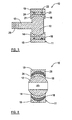
- Figure 1 illustrates a known type of spherical bearing 1 comprising a housing 2 and a ball 3 partially housed within the housing 2.
- the housing 2 comprises a race 4 having a spherical bearing surface 7, a sleeve 5 surrounding the race 4, and an elastomer 6 disposed between and bonded to the race 4 and sleeve 5.
- the race 4 and sleeve 5 are arranged coaxially about a central axis of the housing 2.
- the ball 3 is mounted within the race 4 such that the ball 3 is free to rotate but is prevented from any significant translational movement within the race 4.
- the elastomer 6 serves to absorb displacement of the ball 3 relative to the housing 2 in a radial direction, i.e. in a direction normal to the central axis of the housing 2.
- the bearing assembly 1 is able to dampen radial vibrations as well as compensate for minor misalignments in the objects to which the bearing assembly 1 is mounted.
- a problem with the bearing assembly 1 of Figure 1 is that it is ill-equipped at accommodating forces which act on the ball 3 in a direction parallel to the central axis of the housing 2, referred to hereafter as axial forces.
- Axial forces acting on the ball 3 cause the ball 3 to be displaced axially relative to the housing 2, i.e. in a direction parallel to the central axis.
- axial displacement of the ball 3 causes the race 4 to be displaced in the same direction. This displacement of the race 4 relative to the sleeve 5 creates shearing forces between the race 4 and sleeve 5.
- the bearing assembly 1 of Figure 1 is poorly-equipped at accommodating rotational forces below the threshold torque which may act on the bearing assembly 1, i.e. forces which cause the ball 3 to rotate within the housing 2. Owing to frictional forces which act between the ball 3 and race 4, rotation of the ball 3 within the race 4 encourages the race 4 to similarly rotate. This is particularly true when the bearing 1 is secured to a body by interference fit, which results in the housing 2 being radially compressed. Any rotation of the race 4 relative to the sleeve 5 will again create shearing forces.
- the bearing 1 is designed to facilitate rotation of the ball 3 within the housing 2, the bearing 1 is susceptible to failure with repeated rotation of the ball 3 below the threshold torque, due to shearing of the race:elastomer and/or sleeve:elastomer interfaces.
- DE-10124843 discloses a housing and a ball, with a cylindrical slide bush inserted between the housing and ball.
- GB 2106173 (corresponding to the preamble of independent product claim 1 and 11) discloses a ball and socket joint. A resilient elastomeric bush inserted between a bearing cup and a socket housing.
- the present invention as defined in claim 1 provides a bearing assembly comprising a housing and a ball at least partially housed within the housing, the housing comprising a race having a concave bearing surface and receiving at least a portion of the ball, a sleeve surrounding the race, and a resilient member disposed between the race and the sleeve, characterised in that the surfaces of the race and sleeve adjacent the resilient member and the surfaces of the resilient member include at least one pair of a co-operating protrusion and recess.
- the at least one protrusion and recess co-operate such that the resilient member is compressed upon rotating the race relative to the sleeve.
- the race and sleeve are arranged coaxially about a central axis and the at least one protrusion and recess co-operate such that the resilient member is compressed upon rotating the race relative to the sleeve about the central axis.
- At least one co-operating protrusion and recess are annular.
- each protrusion and recess has a curved profile.
- the resilient member is of uniform thickness and the surface of the race adjacent the resilient member includes one or more protrusions and recesses and the surface of the sleeve adjacent the resilient member includes one or more co-operating recesses or protrusions.
- the surfaces of the race and sleeve adjacent the resilient member are respectively convex and concave.
- the surfaces of the race and sleeve adjacent the resilient member have different curvatures or ellipticities.
- At least one of the surfaces of the race and sleeve adjacent the resilient member is rippled.
- the surfaces of the race and sleeve adjacent the resilient member include at least one pair of a protrusion and protrusion or protrusion and recess which engage with one another upon displacement of the race relative to the sleeve so as to prevent any further displacement of the race relative to the sleeve.
- the present invention as defined in claim 11 provides a bearing assembly comprising a housing and a ball at least partially housed within the housing, the housing comprising a race having a concave bearing surface and receiving at least a portion of the ball, a sleeve surrounding the race, and a resilient member disposed between the race and the sleeve, characterised in that the surfaces of the race and the sleeve adjacent the resilient member are respectively convex and concave and have different curvatures.
- At least one of the surfaces of the race and sleeve adjacent the resilient member has a non-spherical curvature, i.e. a non-zero ellipticity.
- the thickness of the resilient member is non-uniform.
- the resilient member is thicker at the centre of the housing than at the ends of the housing.
- the resilient member is thicker at the ends of the housing than at the centre of the housing.
- the surfaces of the race and sleeve adjacent the resilient member and the surfaces of the resilient member include at least one pair of a co-operating protrusion and recess.
- the ball and the bearing surface of the race are spherical.
- the ball includes one or more arms.
- the ball includes a bore.
- a self-lubricating liner is provided between the race and ball.
- the present invention as defined in claim 21 provides a method of manufacturing a bearing assembly comprising the steps of: providing a ball; surrounding the ball with a race having a concave bearing surface; surrounding the race with a sleeve; and providing a resilient member between the race and the sleeve, wherein the surfaces of the race and sleeve adjacent the resilient member and the surfaces of the resilient member include at least one pair of a co-operating protrusion and recess.
- the step of surrounding the ball with a race comprises swaging the race onto the ball.
- the steps of surrounding the race with a sleeve and providing a resilient member between the race and sleeve comprises surrounding the race with the resilient member and swaging the sleeve over the resilient member.
- the step of providing the resilient member includes moulding an elastomer onto the race by an injection process.
- the elastomer is additionally moulded onto the sleeve.
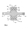
- the bearing assembly 10 of Figure 2 comprises a housing 11 within which a ball 12 is partially housed and rotatably mounted.
- the ball 12 is preferably spherical. However, as is noted below, the shape of the ball 12 may alternatively be spheroid.
- the ball 12 of the bearing assembly 10 illustrated in Figure 2 is a complete sphere. However, only the portion of the ball 12 which engages with (i.e. contacts) the housing 11 need be spherical. Consequently the ball 12 may alternatively be an incomplete sphere or spheroid, as illustrated in Figures 3 and 5 .
- the ball 12 is attached to a pair of arms 13, each arm extending on opposite sides of the ball 12 in a direction away from the housing 11.
- the ball 12 and arms 13 are preferably integral so as to form a single element.
- the arms 13 serve to mount the bearing assembly 10 to other components and may be provided, for example, with a screw thread 26 or bore 27.
- the ball 12 may instead be attached to a single arm 13, as illustrated in the embodiment of Figure 3 .
- the ball 12 may have no attaching arms and instead include a bore 20 for receiving a shaft, axle or the like.
- the housing 11 comprises a race 14 having a concave bearing surface 17, a sleeve 15 arranged about the race 14 and a resilient member 16 disposed between the race 14 and the sleeve 15.
- the race 14 and sleeve 15 are arranged coaxially about a central axis of the housing 11.
- the ball 12 is mounted within the race 14 such that the ball 12 is free to rotate in at least one direction (and preferably in all directions) within the race 14.
- the shape or curvature of the bearing surface 17 of the race 14 preferably conforms to that of the ball 12.
- both the ball 12 and the bearing surface 17 of the race 14 are preferably spherical. That is to say, the bearing surface 17 and the portion of the ball 12 mounted within the race 14 have spherical curvatures.
- a non-spherical ball 12 and bearing surface 17 e.g. an oblate or prolate spheroid
- the diameter of the bearing surface 17 is preferably only slightly greater than that of the ball 12 such that rotation of the ball 12 is permitted whilst any significant translational movement of the ball 12 within the race 14 is prevented.
- the resilient member 16 preferably extends completely around the outermost surface 18 of the race 14 so as to form a collar between the race 14 and sleeve 15. Additionally, the resilient member 16 is preferably made of an elastomeric material, such as rubber. However, other means of providing resilience, such as a sealed fluid, may alternatively be used.
- the outermost surface 18 of the race 14 adjacent the resilient member 16 is convex and the innermost surface 19 of the sleeve 15 adjacent the resilient member 16 is concave.
- the surfaces 18, 19 of the race 14 and sleeve 15 adjacent the resilient member 16 have corresponding profiles. That is to say, the degrees of curvature or ellipticities of the surfaces 18, 19 are the same.
- the resilient member 16 is compressed whenever the race 14 and sleeve 15 move relative to one another in an axial direction, i.e. in a direction parallel to the central axis of housing 11. Moreover, as the race 14 and sleeve 15 are further displaced axially relative to one another, the resilient member 16 is further compressed. Consequently, the bearing assembly 10 is well-equipped at absorbing axial forces which act upon the bearing assembly, i.e. which cause the ball 12 to be displaced relative to the housing 11 in a direction towards an open end of the race 14. Moreover, the bearing assembly 10 is particularly well-suited at resisting excessive axial forces which would otherwise cause the elastomer interfaces of the spherical bearing 1 of Figure 1 to shear.
- the outermost surface 18 of the race 14 adjacent the resilient member 16 includes an annular recess or groove 21 and the innermost surface 19 of the sleeve 15 adjacent the resilient member 16 includes an annular protrusion 22.
- the recess 21 and protrusion 22 are aligned and co-operate such that the resilient member 16 is received in the recess 21 and additionally surrounds the protrusion 22.
- any motion of the race 14 relative to the resilient member 16 causes the resilient member to be compressed.
- the race 14 is rotated relative to the resilient member 16 about the same axis as that defining the annular recess 21, which in the embodiment illustrated in Figure 2 is coincident with the central axis of the housing 11.
- any motion of the sleeve 15 relative to the resilient member 16 causes the resilient member 16 to be compressed; again, with the same exception. Consequently, whenever the race 14 and sleeve 15 are displaced relative to one another, the co-operating recess 21 and protrusion 22 cause the resilient member 16 to be compressed.
- compression of the resilient member 16 by the co-operating recess 21 and protrusion 22 increases.
- the recess 21 and protrusion 22 therefore co-operate to resist forces acting upon the bearing assembly 10.
- the race 14 is displaced axially relative to the sleeve 15.
- the co-operating recess 21 and protrusion 22 then cause the resilient member 16 to be compressed so as to provide increasing resistance to axial displacement of the race 14 relative to the sleeve 15.
- the resilient member 16 and the co-operating recess 21 and protrusion 22 act to dampen axial forces and resist excessive axial forces which would otherwise cause the interfaces of the resilient member 16 with the race 14 and/or sleeve 15 to shear.
- the co-operating recess 21 and protrusion 22 additionally serve to absorb rotational forces which act between the ball 12 and the housing 11. Owing to frictional forces which act between the ball 12 and the bearing surface 17 of the race 14, the race 14 experiences a force whenever the ball 12 rotates within the race 14. This is particularly true when the bearing assembly 10 is secured to a body by interference fit. Owing to the radial compression of the housing 11 that results from an interference fit, the race 14 is generally compressed onto the ball 12. Consequently, the frictional forces between the ball 12 and race 14 can be considerable. As the ball 12 rotates within the race 14, the race 14 experiences a displacement in the direction of rotation of the ball 12.
- This displacement of the race 14 relative to the sleeve 13 creates a shearing force, which can result in the interface of the resilient member 16 with the race 14 and/or sleeve 15 failing. This is particularly true when the outermost surface 18 of the race 14 and/or the innermost surface 19 of the sleeve 15 are spherically curved.
- the bearing assembly 10 is able to accommodate not only radial and axial forces, but also rotational forces.
- the resilient member 16 is not compressed whenever the race 14 and sleeve 15 are rotated relative to one another about the axis that defines the annular recess 21. This may be addressed by having a non-annular recess and protrusion.
- more than one pair of protrusions and recesses may be provided on the interface surfaces 18, 19 of the race 14 and sleeve 15. Indeed, the surfaces 18, 19 may be provided with various forms of protrusions and co-operating recesses.
- the protrusion 22 and recess 21 may be in the form of a spiral from one open end of the bearing surface 17 to the other, a plurality of dimples and bumps, or the surfaces 18,19 may be rippled to provide a wavy profile.
- each surface 18, 19 of the race 14 and sleeve 15 may include both protrusions and recesses.
- each protrusion and recess is preferably smooth, i.e. devoid of any sharp corners. This then simplifies the manufacture and assembly of the housing 11, as described below.
- the resilient member 16 is preferably bonded to both the race 14 and sleeve 15. However, as the protrusions 22 and recesses 21 serve to retain the resilient member 16 in position, the resilient member 16 need not necessarily be bonded to either the race 14 or sleeve 15.
- the surfaces 18, 19 of the race 14 and sleeve 15 adjacent the resilient member 16 are preferably curved such that the resilient member 16 is compressed whenever the race 14 and sleeve 15 move relative to one another in an axial direction.
- the surfaces 18, 19 of the race 14 and sleeve 15 may alternatively have respective concave and convex profiles.
- the surfaces 18, 19 of the race 14 and sleeve 15 adjacent the resilient member 16 need not be curved and may equally be planar.
- the surfaces of the resilient member 16 adjacent the race 14 and sleeve 15 are free of any recesses 21 and protrusions 22.
- recesses 21 and protrusions 22 may equally be formed in the surfaces of the resilient member 16.
- FIG 3 illustrates an alternative embodiment of bearing assembly 10 in accordance with the present invention.
- the bearing assembly 10 comprises a housing 11 within which a ball 12 is housed and rotatably mounted.
- the ball 12 is only a partial sphere.
- the ball 12 is completely housed within the housing 11, rather than partially housed as in the embodiment of Figure 2 .
- the ball 12 is connected to a single arm 13 which extends away from the housing 11.
- the arm 13 may be provided, for example, with a thread 26 or bore 27.
- the surfaces 18, 19 of the race 14 and sleeve 15 adjacent the resilient member 16 are planar, i.e. having no curvature. However, one or both of the surfaces 18, 19 may equally be curved. Moreover, the curvature or ellipticity of the surfaces 18, 19 may differ from one another. For example, the curvature of the outermost surface 18 of the race 14 may be spherical (i.e. having an ellipticity of zero) whilst the curvature of the innermost surface 19 of the sleeve 15 may be spheroidal (i.e. having a non-zero ellipticity).
- the resilient member 16 is bonded to the outermost surface 18 of the race 14 and is preferably bonded to the innermost surface 19 of the sleeve 15. However, as is described below, the adjacent surfaces 18, 24 of the sleeve 15 and resilient member 16 have co-operating protrusions 22 and recesses 21 and therefore the resilient member 16 need not be bonded to the sleeve 15.
- the outermost surface 18 of the race 14 and the adjacent surface 23 of the resilient member 16 are smooth, i.e. free of any protrusions or recesses.
- the innermost surface 19 of the sleeve 15, on the other hand, includes a pair of annular protrusions 22 which co-operate with a pair of annular recesses 21 (i.e. grooves) formed on the adjacent surface 24 of the resilient member 16.
- the pairs of recesses 21 and protrusions 22 once again co-operate such that the resilient member 16 is compressed whenever the race 14 and sleeve 15 are displaced relative to one another, either as a result of axial or rotational forces.
- bearing assembly 10 is particularly advantageous when the interface that is likely to shear, upon subjecting the bearing assembly 10 to repeated or excessive axial or rotational forces, is that between the sleeve 15 and the resilient member 16.
- the housing 2 of the spherical bearing 1 of Figure 1 is generally manufactured by moulding the elastomer 6 directly onto the outermost surface of the race 4, applying an adhesive over the exposed surface of the elastomer 6 and then swaging the sleeve 5 onto the elastomer 6.
- the elastomer 6 is more securely bonded to the race 4 than to the sleeve 5. Any shearing of the bearing assembly 1 is therefore likely to occur at the interface of the sleeve 5 and elastomer 6.
- the recesses 21 and protrusions 22 formed on the adjacent surfaces 19, 24 of the sleeve 15 and resilient member 16 co-operate to prevent, or at least significantly reduce the chances of, shearing at this interface.
- recesses 21 and protrusions 22 may be additionally, or alternatively, formed on the outermost surface 18 of the race 14 and the surface 23 of resilient member 16 adjacent the race 14. Again, the recesses 21 and protrusions 22 may take on various forms, e.g. spirals, dimples/bumps, ripples.
- recesses 21 and protrusions 22 are provided on two or more adjacent surfaces 18, 19, 23, 24 of the race 14, sleeve 15 and resilient member 16.
- axial and/or rotational forces acting on the bearing assembly 10 are unlikely to result in the failure of the interfaces between the race 14 and resilient member 16 and between the sleeve 15 and resilient member 16.
- the bearing assembly 10 may suffer from a failure of the resilient member 16 itself.
- the resilient member 16 may shear through the centre or tear at the protrusions 22 and/or recesses 21. A failure of the resilient member 16 or its interfaces could potentially result in the separation of the race 14 from the sleeve 15, and therefore the separation of the ball 12 from the housing 11.
- the surfaces 18, 19 of the race 14 and sleeve 15 adjacent the resilient member 16 are preferably curved.
- the sleeve 15 preferably extends along the race 14 in a direction parallel to the central axis of the housing 11 such that inner diameter of the sleeve 15 (i.e. the diameter of the innermost surface 19 of the sleeve 15) at the ends of the housing 11 is less than the outer diameter of the race 14 (i.e. the diameter of the outermost surface 18 of the race 14) at the centre or equator of the housing 11. Consequently, should either interface or the resilient member 16 fail, the race 14 is prevented from separating from the sleeve 15 in a direction parallel to the central axis of the housing 11.
- one of the surfaces 18, 19 of the race 14 and sleeve 15 adjacent the resilient member 16 includes at least one protrusion and the other surface 18, 19 of the race 14 and sleeve 15 (referred to hereafter as the second surface) includes at least one recess and/or protrusion which engages with the protrusion of the first surface upon failure of the resilient member 16.
- the protrusion of the first surface is prevented from passing the protrusion or recess of the second surface whenever the race 14 and sleeve 15 move relative to one another. Since the protrusion of the first surface is unable to pass the protrusion/recess of the second surface, the race 14 and sleeve 15 are prevented from separating.
- Figures 4a and 4b illustrate possible examples of recesses 21 and protrusions 22 formed on the surfaces 18, 19 of the race 14 and sleeve 15 which engage upon failure of the resilient member 16.
- a recess 21 is formed in the surface 18 of the race 14 and a co-operating protrusion 22 is formed on the surface of the sleeve 15.
- the resilient member 16 is of uniform thickness and is free of any recesses or protrusions.
- the depth of the recess 21 and height of the protrusion 22 are each greater than the thickness of the resilient member 16. Accordingly, the protrusion 22 is prevented from escaping the recess 21 should any failure of the resilient member 16 or its interfaces with the race 14 or sleeve 15 occur.
- a pair of protrusions 22a are formed on the surface 18 of the race 14, and a single protrusion 22b is formed on the surface 19 of the sleeve 15 at a position between the two protrusions 22a of the race 14.
- the resilient member 16 in this example includes three recesses 21, each recess 21 being formed at and co-operating with a protrusion 22a, 22b.
- the height of each protrusion 22a, 22b is greater than half the normal thickness of the resilient member 16. More precisely, the total height of any pair of engaging protrusions 22a, 22b is greater than the thickness of the resilient member 16.
- the single protrusion 22b of the sleeve 15 is prevented from passing either of the protrusions 22a of the race 14 upon failure of the resilient member 16 or its interfaces.
- Figure 5 illustrates a further embodiment of a bearing assembly 10 in accordance with the present invention.
- the ball 12 of the assembly 10 is an incomplete sphere housed entirely within the housing 11 and has a bore 20 through the centre for receiving a shaft, axle or the like.
- the ball 12 may alternatively be a complete sphere (or complete/partial spheroid) and may include one or more arms attached to the ball 12.
- the outermost surface 18 of the race 14 is convex whilst the innermost surface 19 of the sleeve 15 is concave.
- the degree of curvature or ellipticity of the innermost surface 19 of the sleeve 15 is greater than that of the outermost surface 18 of the race 14, i.e. the surface 19 of the sleeve 15 is more concave than the surface 18 of the race is convex.
- the resilient member 16 is of non-uniform thickness and is thicker at the centre or equator of the housing 11 than at the ends of the housing 11.
- the outermost surface 18 of the race 14 and innermost surface 19 of the sleeve 15 have the same degree of curvature or ellipticity; a planar surface is one having no degree of curvature or an ellipticity equal to 1.
- the resilient member 16 may be regarded as having a uniform thickness. Even when the resilient member 16 includes one or more recesses or protrusions, the thickness of the resilient member 16 at all points free from protrusion or recess is constant. In contrast, the resilient member 16 of the bearing assembly 10 of Figure 5 varies in thickness.
- the surfaces 18, 19, 23, 24 of the race 14, sleeve 15 and resilient member 16 adjacent one another are preferably free of recesses 21 and protrusions 22.
- the surfaces 18, 19, 23, 24 may nevertheless be provided with one or more pairs of co-operating protrusions and recesses.
- one or more pairs of co-operating protrusions and recesses may be formed on the outermost surface 18 of the race 14 and the adjacent surface 23 of the resilient member 16.
- This design of bearing assembly 10 is particularly advantageuous when the interface that is likely to shear, upon subjecting the bearing assembly 10 to repeated or excessive axial or rotational forces, is that between the sleeve 15 and the resilient member 16. Owing to the concave shape of the surface 19 of the sleeve 15, any axial displacement of the race 14 relative to the sleeve 15 will cause the resilient member 16 to be compressed against the surface 19 of the sleeve 15. As a result, the race 14 and sleeve 15 are prevented form separating.
- the curvature of the innermost surface 19 of the sleeve 15 is preferably non-spherical, i.e. having a non-zero ellipticity. Accordingly, any rotation of the race 14 relative to the sleeve 15 will cause the resilient member 16 to be compressed against the concave surface 19 of the sleeve 15; the only exception to this is when the race 14 and sleeve 15 rotate relative to one another about the central axis of the housing 11.
- the innermost surface 19 of the sleeve 15 is oblate, and more preferably having an oblate ellipticity (sqrt(1-(c/a) 2 ) of between 0.80 and 0.97.
- the resilient member 16 is thicker at the ends of the housing 11 that at the centre or equator of the housing 11.
- the outermost surface 18 of the race 14 is preferably curved (convex or concave) such that the race 14 and sleeve 15 are additionally prevented from separating upon failure of the race:resilient member interface. Nevertheless, the surface 18 of the race 14 may alternatively be planar, particularly when the resilient member 16 is securely bonded to the race 14 (e.g. by directly moulding the resilient member 16 onto the race).
- a lubricant or self-lubricating liner may be provided between the ball 12 and the bearing surface 17 of the race 14 to reduce friction.
- Figure 6 illustrates a further embodiment of bearing assembly 10 in which the resilient member 16 is provided as part of an insert 25.
- the insert 25 comprises an inner cylindrical wall 28 and an outer cylindrical wall 29, which surrounds and is coaxial with the inner wall 28.
- the resilient member 16 is disposed between the inner 28 and outer 29 walls of the insert 25.
- the insert 25 is inserted between the race 14 and the sleeve 15 during manufacture of the bearing assembly 10. Once inserted between the race 14 and the sleeve 15, the inner wall 28 of the insert 25 forms part of the race 14, and the outer wall 29 of the insert 25 forms part of the sleeve 15.
- the innermost surface 30 of the inner wall 28 and the outermost surface 31 of the outer wall 29 are flat annular surfaces.
- the outermost surface 18 of the race 14 and the innermost surface 19 of the sleeve are flat annular surfaces. Consequently, the insert 25 may be easily inserted between the race 14 and sleeve 15.
- the ends 32 of the inner 28 and outer 29 walls are deformable and are staked over the ends of the race 14 and the sleeve 15 after the insert 25 has been inserted such that the insert 25 is firmly retained between the race 14 and sleeve 15.
- the surfaces of the inner 28 and outer 29 walls adjacent the resilient member 16 include pairs of co-operating recesses 21 and protrusions 22. As described above in relation to the embodiments of Figures 2 to 5 , recesses and protrusions may be formed on any two or more surfaces selected from the surfaces of the resilient member 16 and the surfaces of the inner 28 and outer 29 walls adjacent the resilient member 16. Additionally, or alternatively, the surfaces of the inner 28 and outer 29 walls adjacent the resilient member 16 may have different curvatures such that resilient member is of non-uniform thickness.
- the bearing assembly 10 is preferably manufactured by first swaging the race 14 onto the ball 12. Any protrusions or recesses are then machined on the outermost surface 18 of the race 14.
- the resilient member 16 is then bonded onto the outermost surface 18 of the race 14.
- the resilient member 16 is preferably an elastomer moulded directly onto the outermost surface 18 of the race 14 by injection moulding. By moulding the resilient member 16 directly on the race 14, the resilient member 16 fills any recesses and surrounds any protrusions formed on the outermost surface 18 of the race 14. Any protrusions or recesses to be formed in the outermost surface 24 of the resilient member 16 are preferably formed in the moulding processes.
- the innermost surface 19 of the sleeve 15 is then machined to include any necessary protrusions or recesses. Finally, the sleeve 15 is swaged on to the resilient member 16. Prior to swaging the sleeve 15 on to the resilient member 16, a layer of adhesive is preferably applied between the sleeve 15 and resilient member 16 such that the resilient member 16 is bonded to the sleeve 15.
- the elasticity of the bearing assembly 10 depends upon the degree by which the resilient member 16 is compressed between the race 14 and sleeve 15.
- the resilient member 16 is compressed evenly, i.e. the degree of compression is the same at all points on the resilient member 16, such that the elasticity of the bearing assembly 10 is consistent.
- the calculations required to compress the resilient member 16 evenly are much simpler.
- swaging the sleeve 15 onto the resilient member 16 to achieve even compression of the resilient member 16 is made much simpler.
- the sleeve 15 may first be positioned about the race 14 and then the resilient member 16 moulded between the race 14 and sleeve 15. In this manner, the resilient member 16 is directly bonded to both the race 14 and sleeve 15.
- the resilient member 16 may be moulded in a separate process and then pulled over the outermost surface 18 of the race 14.
- the housing 11 may be formed as a separate element and then swaged onto the ball 12.
- the bearing assembly of the present invention With the bearing assembly of the present invention, axial and rotational forces are absorbed and dampened more effectively than is possible with known spherical bearings.
- the bearing assembly is able to resist axial and rotational forces which would otherwise cause the elastomer interfaces of known spherical bearings to shear.
Landscapes
- Engineering & Computer Science (AREA)
- General Engineering & Computer Science (AREA)
- Mechanical Engineering (AREA)
- Physics & Mathematics (AREA)
- Geometry (AREA)
- Support Of The Bearing (AREA)
- Sliding-Contact Bearings (AREA)
- Electron Tubes For Measurement (AREA)
- Magnetic Bearings And Hydrostatic Bearings (AREA)
- Mounting Of Bearings Or Others (AREA)
- Packaging Of Annular Or Rod-Shaped Articles, Wearing Apparel, Cassettes, Or The Like (AREA)
Claims (25)
- Lageranordnung (10), umfassend ein Gehäuse (11) und eine Kugel (12), die mindestens teilweise in dem Gehäuse (11) untergebracht ist, wobei das Gehäuse (11) einen Laufring (14) umfasst, der über eine konkave Lauffläche (17) verfügt und mindestens einen Abschnitt der Kugel (12) aufnimmt, eine den Laufring (14) umgebende Buchse (15) und ein elastisches Element (16), das zwischen dem Laufring (14) und der Buchse (15) angeordnet ist,
dadurch gekennzeichnet, dass: die Oberflächen (18, 19) des Laufrings (14) und der Buchse (15) angrenzend an das elastische Element (16) und die Oberflächen (23, 24) des elastischen Elements (16) mindestens ein zusammenwirkendes Paar aus einer Vorwölbung (22) und einer Aussparung (21) enthalten. - Lagerandordnung (10) gemäß Anspruch 1, wobei die mindestens eine Vorwölbung (22) und Aussparung (21) so zusammenwirken, dass mindestens ein Abschnitt des elastischen Elements (16) komprimiert wird, wenn eine Rotation des Laufrings (14) im Verhältnis zu der Buchse (15) erfolgt.
- Lagerandordnung (10) gemäß Anspruch 2, wobei der Laufring (14) und die Buchse (15) koaxial um eine Mittelachse angeordnet sind und die mindestens eine Vorwölbung (22) und Aussparung (21) so zusammenwirken, dass mindestens ein Abschnitt des elastischen Elements (16) komprimiert wird, wenn eine Rotation des Laufrings (14) im Verhältnis zu der Buchse (15) um die Mittelachse erfolgt.
- Lageranordnung (10) gemäß einem der vorherigen Ansprüche, wobei mindestens eine zusammenwirkende Vorwölbung (22) und Aussparung (21) ringförmig sind.
- Lageranordnung (10) gemäß einem der vorherigen Ansprüche, wobei jede Vorwölbung (22) und Aussparung (21) ein gekrümmtes Profil haben.
- Lageranordnung (10) gemäß einem der vorherigen Ansprüche, wobei das elastische Element (16) eine gleichmäßige Dicke hat und die Oberfläche (18) des Laufrings (14) angrenzend an das elastische Element (16) eine oder mehrere Vorwölbungen (22) und Aussparungen (21) enthält und die Oberfläche (19) der Buchse (15) angrenzend an das elastische Element (16) eine oder mehrere zusammenwirkende Aussparungen (21) oder Vorwölbungen (22) enthält.
- Lageranordnung gemäß einem der vorherigen Ansprüche, wobei die Oberflächen (18, 19) des Laufrings (14) und der Buchse (15) angrenzend an das elastische Element (16) jeweils konvex beziehungsweise konkav sind.
- Lageranordnung (10) gemäß einem der vorherigen Ansprüche, wobei die Oberflächen (18, 19) des Laufrings (14) und der Buchse (15) angrenzend an das elastische Element (16) unterschiedliche Krümmungen aufweisen.
- Lageranordnung (10) gemäß einem der vorherigen Ansprüche, wobei mindestens eine der Oberflächen (18, 19) des Laufrings (14) und der Buchse (15) angrenzend an das elastische Element (16) geriffelt ist.
- Lageranordnung (10) gemäß einem der vorherigen Ansprüche, wobei die Oberflächen (18, 19) des Laufrings (14) und der Buchse (15) angrenzend an das elastische Element (16) mindestens ein Paar aus einer Vorwölbung (22) und einer Vorwölbung (22) oder aus einer Vorwölbung (22) und einer Aussparung (21) enthalten, die miteinander in Eingriff kommen, wenn der Laufring (14) im Verhältnis zu der Buchse (15) verschoben wird, um jede weitere Verschiebung des Laufrings (14) im Verhältnis zur Buchse (15) zu verhindern.
- Lageranordnung (10), umfassend ein Gehäuse (11) und eine Kugel (12), die mindestens teilweise in dem Gehäuse (11) untergebracht ist, wobei das Gehäuse (11) einen Laufring (14) umfasst, der über eine konkave Lauffläche (17) verfügt und mindestens einen Abschnitt der Kugel (12) aufnimmt, eine den Laufring (14) umgebende Buchse (15) und ein elastisches Element (16), das zwischen dem Laufring (14) und der Buchse (15) angeordnet ist,
dadurch gekennzeichnet, dass: die Oberflächen (18, 19) des Laufrings (14) und der Buchse (15) angrenzend an das elastische Element (16) jeweils konvex beziehungsweise konkav sind und unterschiedliche Krümmungen aufweisen. - Lageranordnung (10) gemäß Anspruch 11, wobei mindestens eine der Oberflächen (18, 19) des Laufrings (14) und der Buchse (15) angrenzend an das elastische Element (16) eine nichtsphärische Krümmung aufweist.
- Lageranordnung (10) gemäß einem der Ansprüche 11 bis 12, wobei die Dicke des elastischen Elements (16) ungleichmäßig ist.
- Lageranordnung (10) gemäß Anspruch 13, wobei das elastische Element (16) in der Mitte des Gehäuses (11) dicker ist als an den Enden des Gehäuses (11).
- Lageranordnung (10) gemäß Anspruch 14, wobei das elastische Element (16) an den Enden des Gehäuses (11) dicker ist als in der Mitte des Gehäuses (11).
- Lageranordnung (10) gemäß einem der Ansprüche 11 bis 15, wobei die Oberflächen (18, 19) des Laufrings (14) und der Buchse (15) angrenzend an das elastische Element (16) und die Oberflächen (23, 24) des elastischen Elements (16) mindestens ein zusammenwirkendes Paar aus einer Vorwölbung (22) und einer Aussparung (21) enthalten.
- Lagerandordnung (10) gemäß einem der vorherigen Ansprüche, wobei die Kugel (12) und die Lauffläche (17) des Laufrings (14) sphärisch sind.
- Lagerandordnung (10) gemäß einem der vorherigen Ansprüche, wobei die Kugel (12) einen oder mehrere Arme (13) hat.
- Lageranordnung (10) gemäß einem der Ansprüche 1 bis 17, wobei die Kugel (12) eine Bohrung (20) enthält.
- Lagerandordnung (10) gemäß einem der vorherigen Ansprüche, wobei zwischen dem Laufring (14) und der Kugel (12) eine selbstschmierende Auskleidung vorgesehen ist.
- Verfahren zur Herstellung einer Lageranordnung (10), das Verfahren umfassend die folgenden Schritte: das Bereitstellen einer Kugel (12); das Einfassen der Kugel (12) mit einem Laufring (14), der eine konkave Lauffläche (17) hat; das Einfassen des Laufrings (14) mit einer Buchse (15); und das Bereitstellen eines elastischen Elements (16) zwischen dem Laufring (14) und der Buchse (15), wobei die Oberflächen (18, 19) des Laufrings (14) und der Buchse (15) angrenzend an das elastische Element (16) und die Oberflächen des elastischen Elements mindestens ein zusammenwirkendes Paar aus einer Vorwölbung (22) und einer Aussparung (21) enthalten.
- Verfahren gemäß Anspruch 21, wobei der Schritt des Einfassens der Kugel (12) mit einem Laufring (14) das Gesenkschmieden des Laufrings (14) auf die Kugel (12) umfasst.
- Verfahren gemäß Anspruch 21 oder 22, wobei die Schritte des Einfassens des Laufrings (14) mit einer Buchse (15) und des Bereitstellens eines elastischen Elements (16) zwischen dem Laufring (14) und der Buchse (15) das Einfassen des Laufrings (14) mit dem elastischen Element (16) und das Gesenkschmieden der Buchse (15) über das elastische Element (16) umfasst.
- Verfahren gemäß einem der Ansprüche 21 bis 23, wobei der Schritt des Bereitstellens des elastischen Elements (16) das Formpressen eines Elastomers auf den Laufring (14) durch einen Einspritzvorgang einschließt.
- Verfahren gemäß Anspruch 24, wobei das Elastomer zusätzlich auf die Buchse (15) formgepresst wird.
Applications Claiming Priority (1)
| Application Number | Priority Date | Filing Date | Title |
|---|---|---|---|
| GB0422182A GB2418963B (en) | 2004-10-06 | 2004-10-06 | A bearing assembly |
Publications (3)
| Publication Number | Publication Date |
|---|---|
| EP1645760A2 EP1645760A2 (de) | 2006-04-12 |
| EP1645760A3 EP1645760A3 (de) | 2007-12-19 |
| EP1645760B1 true EP1645760B1 (de) | 2009-06-03 |
Family
ID=33428164
Family Applications (1)
| Application Number | Title | Priority Date | Filing Date |
|---|---|---|---|
| EP05021644A Expired - Lifetime EP1645760B1 (de) | 2004-10-06 | 2005-10-04 | Lageranordnung |
Country Status (7)
| Country | Link |
|---|---|
| US (1) | US7658546B2 (de) |
| EP (1) | EP1645760B1 (de) |
| JP (1) | JP2006105394A (de) |
| CN (1) | CN1757944A (de) |
| AT (1) | ATE433057T1 (de) |
| DE (1) | DE602005014719D1 (de) |
| GB (2) | GB2418963B (de) |
Families Citing this family (37)
| Publication number | Priority date | Publication date | Assignee | Title |
|---|---|---|---|---|
| DE102009026739A1 (de) * | 2009-06-04 | 2010-12-09 | Zf Friedrichshafen Ag | Gelenk- und/oder Lageranordnung mit einer elastischen Zwischenlage |
| KR101225742B1 (ko) * | 2009-08-10 | 2013-02-12 | 주식회사 일진 | 자동차용 볼 조인트 어셈블리 |
| CA2686843A1 (en) * | 2009-12-02 | 2011-06-02 | Flywheel Energy Systems Inc. | Compliant bearing mount with a position restoring shear force absorber |
| CN103025454B (zh) * | 2010-05-28 | 2015-07-29 | Skf公司 | 包括径向中间接头的组件以及结合两个部件的对应方法 |
| KR101312710B1 (ko) * | 2010-06-14 | 2013-10-01 | 주식회사 일진 | 차량용 샤시 부품 연결용 단일축 댐핑 조인트 |
| DE102010042118A1 (de) * | 2010-10-07 | 2012-04-12 | Robert Bosch Gmbh | Gleitlager, Verfahren zum Herstellen eines Gleitlagers sowie Verwendung eines Gleitlagers |
| WO2012068237A1 (en) * | 2010-11-16 | 2012-05-24 | Roller Bearing Company Of America, Inc. | Spherical plain bearing and method for assembling the same |
| US9316257B2 (en) | 2011-04-01 | 2016-04-19 | Roller Bearing Company Of America, Inc. | Spherical bearing with sealing member member |
| US9958011B2 (en) | 2011-04-01 | 2018-05-01 | Roller Bearing Company Of America, Inc. | Bearing assembly having surface protrusions and a seal |
| WO2013000517A1 (en) * | 2011-06-30 | 2013-01-03 | Schaublin Sa | Spherical plain bearing with constant torque |
| US8783953B2 (en) | 2011-07-21 | 2014-07-22 | Roller Bearing Company Of America, Inc. | Low friction seal for bearings |
| DE102012207527B4 (de) * | 2012-05-07 | 2022-12-29 | Zf Friedrichshafen Ag | Hülsengelenk für ein Fahrzeug |
| US9010679B2 (en) * | 2012-06-26 | 2015-04-21 | Bell Helicopter Textron Inc. | Hybrid spherical and thrust bearing |
| US9840325B2 (en) * | 2012-06-26 | 2017-12-12 | Bell Helicopter Textron Inc. | Dual series pitch link bearing |
| CN103161820A (zh) * | 2013-04-07 | 2013-06-19 | 赵丰 | 带旋转式接头的反作用杆总成 |
| JP6267456B2 (ja) * | 2013-08-23 | 2018-01-24 | 東洋ゴム工業株式会社 | 走行車両用弾性ブッシュの製造方法 |
| US9562567B2 (en) | 2014-02-07 | 2017-02-07 | Roller Bearing Company Of America, Inc. | Spherical bearing with axially compressed annular seal |
| EP2905486B1 (de) | 2014-02-11 | 2019-05-29 | Roller Bearing Company of America, Inc. | Verpresste lageranordnung mit darauf montiertem flansch |
| US9353792B2 (en) | 2014-02-19 | 2016-05-31 | Google Inc. | Biased compound radial plain bearing for increased life in oscillating pivot motion |
| US9764831B2 (en) * | 2014-03-10 | 2017-09-19 | Bell Helicopter Textron Inc. | Articulated main rotor hub with inwardly CF bearing and 3% flapping hinge offset |
| CN104314993B (zh) * | 2014-06-22 | 2016-10-26 | 廖应良 | 一种耙用调心轴承座总成 |
| CN104482054A (zh) * | 2014-11-14 | 2015-04-01 | 东方电气集团东方汽轮机有限公司 | 大型高速旋转机械的轴承 |
| JP2016200251A (ja) * | 2015-04-14 | 2016-12-01 | 日本電産テクノモータ株式会社 | 軸受装置およびモータ |
| CN106487155B (zh) * | 2015-08-31 | 2024-07-02 | 德昌电机(深圳)有限公司 | 液泵、电机及其轴套单元 |
| US9856910B2 (en) | 2015-11-30 | 2018-01-02 | Roller Bearing Company Of America, Inc. | Self-lubricated thrust bearing for a hinged aircraft wing |
| DE102016220438A1 (de) * | 2016-10-19 | 2018-04-19 | Zf Friedrichshafen Ag | Hülsengelenk, insbesondere für ein Fahrzeug |
| DE102016225127A1 (de) | 2016-12-15 | 2018-06-21 | Zf Friedrichshafen Ag | Gelenk für ein Fahrzeug und Verfahren zum Herstellen eines solchen Gelenkes |
| DE102017111668B4 (de) * | 2017-05-29 | 2021-06-02 | Benteler Automobiltechnik Gmbh | Lagerbuchse |
| CN110914000B (zh) * | 2017-07-05 | 2023-03-28 | M-I有限公司 | 球形弹性体支座 |
| CN107339343A (zh) * | 2017-08-27 | 2017-11-10 | 湖南运达机电科技股份有限公司 | 一种汽车用制动蹄浮动凸轮鼓式制动器 |
| US10604244B2 (en) * | 2017-11-16 | 2020-03-31 | Aktiebolaget Skf | Combination elastomeric and ellipsoidal plain bearing |
| US10371200B2 (en) * | 2017-12-06 | 2019-08-06 | Aktiebolaget Skf | Combination elastomeric and cylindrical plain bearing |
| CN109048871A (zh) * | 2018-10-23 | 2018-12-21 | 国运科技(大连)有限公司 | 一种机械手 |
| DE102019203271B3 (de) * | 2019-03-11 | 2019-08-22 | Zf Friedrichshafen Ag | Gelenk für ein Fahrwerk eines Fahrzeugs, Strukturbauteil für ein Fahrwerk eines Fahrzeugs mit einem solchen Gelenk |
| CN110762121A (zh) * | 2019-11-29 | 2020-02-07 | 江苏希西维轴承有限公司 | 一种用于轨道交通连接的精密轴承 |
| DE102022105703A1 (de) * | 2022-03-10 | 2023-09-14 | Vibracoustic Se | Lageranordnung |
| CN120530270A (zh) * | 2023-10-26 | 2025-08-22 | 马渊马达株式会社 | 轴承保持装置以及马达 |
Family Cites Families (32)
| Publication number | Priority date | Publication date | Assignee | Title |
|---|---|---|---|---|
| US2488775A (en) * | 1943-07-24 | 1949-11-22 | Heim Company | Bearing |
| GB600265A (en) * | 1944-10-16 | 1948-04-05 | Thompson Prod Inc | Improvements in or relating to ball and socket joints |
| US2804679A (en) * | 1954-08-23 | 1957-09-03 | Southwest Products Co | Method of making bearings and rod end bearings |
| US2856203A (en) * | 1954-09-29 | 1958-10-14 | American Steel Foundries | Fifth wheel bracket |
| US3162930A (en) * | 1961-04-11 | 1964-12-29 | Fafnir Bearing Co | Method of making antifiriction bearings |
| US3193910A (en) * | 1962-10-01 | 1965-07-13 | Southwest Products Co | Method of making bearings |
| US3583775A (en) * | 1968-06-20 | 1971-06-08 | Textron Inc | Spherical bearing and method of making the same |
| US3754802A (en) * | 1972-01-25 | 1973-08-28 | Mpb Corp | Self-aligning bearing assembly |
| JPS5137365A (de) * | 1974-09-27 | 1976-03-29 | Toshio Hata | |
| JPS5224658A (en) * | 1975-08-18 | 1977-02-24 | Saitama Kiki Kk | Non-oil feeding bearing of ball joint |
| US4034996A (en) * | 1975-10-08 | 1977-07-12 | Saitamakiki Co., Ltd. | Ball joint for torque rod |
| DE2630205A1 (de) * | 1976-07-05 | 1978-01-19 | Hurth Masch Zahnrad Carl | Kippzapfen fuer gelenke, insbesondere kardangelenke o.dgl. |
| GB2103757A (en) * | 1981-08-11 | 1983-02-23 | Btr Plc | Improvements in bushes |
| GB2106173B (en) * | 1981-09-22 | 1985-03-27 | Automotive Products Plc | Ball and socket joints |
| US4844627A (en) * | 1983-07-25 | 1989-07-04 | Mcdonnell Douglas Corporation | Interference fit bearings |
| DE3933163A1 (de) * | 1988-10-27 | 1990-05-03 | Toyoda Gosei Kk | Zylindrische daempfungsbuchse |
| US5033722A (en) * | 1989-08-21 | 1991-07-23 | Caterpillar Inc. | Resilient mount assembly |
| DE4138609C2 (de) * | 1991-11-25 | 1997-07-17 | Lemfoerder Metallwaren Ag | Kugelhülsen-Zentralgelenk |
| JPH05199184A (ja) | 1992-01-20 | 1993-08-06 | Fujitsu Ltd | 光増幅中継器 |
| US5178482A (en) * | 1992-01-22 | 1993-01-12 | Trw Inc. | Ball joint |
| GB2263948B (en) * | 1992-01-31 | 1996-03-06 | Minebea Co Ltd | Spherical bearing |
| DE4216559C2 (de) * | 1992-05-20 | 1995-05-24 | Freudenberg Carl Fa | Schwenklager |
| DE4240099C1 (de) * | 1992-11-28 | 1994-05-19 | Schaeffler Waelzlager Kg | Lageranordnung zur spielfreien Einstellung einer Welle |
| US5697723A (en) * | 1995-12-12 | 1997-12-16 | Trw Inc. | Joint assembly |
| JPH09177778A (ja) * | 1995-12-27 | 1997-07-11 | Minebea Co Ltd | 球面すべり軸受 |
| US5902050A (en) * | 1996-05-31 | 1999-05-11 | Lord Corporation | Spherical elastomeric bearing assembly |
| DE19736106B4 (de) * | 1997-08-20 | 2006-03-23 | Ina-Schaeffler Kg | Lagerung eines Schalthebels für eine Außenschaltung eines Kraftfahrzeuggetriebes |
| DE19830593C1 (de) * | 1998-07-09 | 2000-02-17 | Sachsenring Entwicklungsgesell | Kugelgelenk und Verfahren zu dessen Herstellung |
| JP2002276652A (ja) * | 2001-03-19 | 2002-09-25 | Kawasaki Steel Corp | 円筒ころ軸受 |
| DE10124843A1 (de) | 2001-05-22 | 2002-11-28 | Ina Schaeffler Kg | Gleitlager |
| DE10150189A1 (de) * | 2001-10-12 | 2003-04-17 | Zf Lemfoerder Metallwaren Ag | Schwingungsgedämpfes Gummilager |
| JP2003247540A (ja) | 2002-02-26 | 2003-09-05 | Minebea Co Ltd | 転がり軸受及びロッドエンド軸受 |
-
2004
- 2004-10-06 GB GB0422182A patent/GB2418963B/en not_active Withdrawn - After Issue
- 2004-10-06 GB GB0620736A patent/GB2428752B/en not_active Withdrawn - After Issue
-
2005
- 2005-09-30 JP JP2005287790A patent/JP2006105394A/ja not_active Withdrawn
- 2005-10-04 US US11/243,414 patent/US7658546B2/en not_active Expired - Fee Related
- 2005-10-04 AT AT05021644T patent/ATE433057T1/de not_active IP Right Cessation
- 2005-10-04 DE DE602005014719T patent/DE602005014719D1/de not_active Expired - Lifetime
- 2005-10-04 EP EP05021644A patent/EP1645760B1/de not_active Expired - Lifetime
- 2005-10-08 CN CNA2005101082616A patent/CN1757944A/zh active Pending
Also Published As
| Publication number | Publication date |
|---|---|
| GB0422182D0 (en) | 2004-11-03 |
| US7658546B2 (en) | 2010-02-09 |
| GB0620736D0 (en) | 2006-11-29 |
| GB2418963B (en) | 2007-04-04 |
| CN1757944A (zh) | 2006-04-12 |
| JP2006105394A (ja) | 2006-04-20 |
| GB2418963A (en) | 2006-04-12 |
| GB2428752A (en) | 2007-02-07 |
| EP1645760A2 (de) | 2006-04-12 |
| EP1645760A3 (de) | 2007-12-19 |
| US20060098908A1 (en) | 2006-05-11 |
| DE602005014719D1 (de) | 2009-07-16 |
| ATE433057T1 (de) | 2009-06-15 |
| GB2428752B (en) | 2007-03-14 |
Similar Documents
| Publication | Publication Date | Title |
|---|---|---|
| US7658546B2 (en) | Bearing assembly | |
| EP3464915B1 (de) | Kugelgelenk und verfahren dazu | |
| US9709089B2 (en) | Combination spherical and laminated bearing assembly | |
| US6695521B2 (en) | Isolation ball joint for steering and suspension | |
| US4430016A (en) | Ball joint | |
| CN109312776B (zh) | 插槽组件和制造插槽组件的方法 | |
| US6454484B1 (en) | Compliant pivot socket for automotive steering | |
| US6413003B1 (en) | Compliant pivot socket for automotive steering | |
| CA2792309A1 (en) | Ball joint for automotive suspension | |
| KR20030019564A (ko) | 볼 조인트 | |
| US4913411A (en) | High-capacity elastomeric combination journal-thrust bearing | |
| CN109072968A (zh) | 用于插槽组件的护罩 | |
| JPS6098216A (ja) | 接触角をもつ軸受を備えた回転支持装置 | |
| US5573463A (en) | Elastomeric drive line coupling for transmitting torque and simultaneously accomodating shaft misalignments and angular deflections | |
| EP1776533A1 (de) | Buchse | |
| CN211778499U (zh) | 球窝组件和车辆中的实心车桥组件 | |
| WO2019217768A1 (en) | Compression loaded ball socket assembly | |
| US10584737B2 (en) | Compression loaded ball socket assembly | |
| RU2114333C1 (ru) | Сферический шарнир | |
| US11162539B2 (en) | Constant velocity joint and assembly method therefor | |
| JPS6341260Y2 (de) | ||
| KR20220077382A (ko) | 스프링 히스테리시스 저감 장치 | |
| CN119616996A (zh) | 一种耐用的接头总成及反作用杆总成 |
Legal Events
| Date | Code | Title | Description |
|---|---|---|---|
| PUAI | Public reference made under article 153(3) epc to a published international application that has entered the european phase |
Free format text: ORIGINAL CODE: 0009012 |
|
| AK | Designated contracting states |
Kind code of ref document: A2 Designated state(s): AT BE BG CH CY CZ DE DK EE ES FI FR GB GR HU IE IS IT LI LT LU LV MC NL PL PT RO SE SI SK TR |
|
| AX | Request for extension of the european patent |
Extension state: AL BA HR MK YU |
|
| PUAL | Search report despatched |
Free format text: ORIGINAL CODE: 0009013 |
|
| AK | Designated contracting states |
Kind code of ref document: A3 Designated state(s): AT BE BG CH CY CZ DE DK EE ES FI FR GB GR HU IE IS IT LI LT LU LV MC NL PL PT RO SE SI SK TR |
|
| AX | Request for extension of the european patent |
Extension state: AL BA HR MK YU |
|
| 17P | Request for examination filed |
Effective date: 20080519 |
|
| AKX | Designation fees paid |
Designated state(s): AT BE BG CH CY CZ DE DK EE ES FI FR GB GR HU IE IS IT LI LT LU LV MC NL PL PT RO SE SI SK TR |
|
| 17Q | First examination report despatched |
Effective date: 20090114 |
|
| GRAP | Despatch of communication of intention to grant a patent |
Free format text: ORIGINAL CODE: EPIDOSNIGR1 |
|
| GRAS | Grant fee paid |
Free format text: ORIGINAL CODE: EPIDOSNIGR3 |
|
| GRAA | (expected) grant |
Free format text: ORIGINAL CODE: 0009210 |
|
| AK | Designated contracting states |
Kind code of ref document: B1 Designated state(s): AT BE BG CH CY CZ DE DK EE ES FI FR GB GR HU IE IS IT LI LT LU LV MC NL PL PT RO SE SI SK TR |
|
| REG | Reference to a national code |
Ref country code: GB Ref legal event code: FG4D |
|
| REG | Reference to a national code |
Ref country code: CH Ref legal event code: EP |
|
| REG | Reference to a national code |
Ref country code: IE Ref legal event code: FG4D |
|
| REF | Corresponds to: |
Ref document number: 602005014719 Country of ref document: DE Date of ref document: 20090716 Kind code of ref document: P |
|
| PG25 | Lapsed in a contracting state [announced via postgrant information from national office to epo] |
Ref country code: FI Free format text: LAPSE BECAUSE OF FAILURE TO SUBMIT A TRANSLATION OF THE DESCRIPTION OR TO PAY THE FEE WITHIN THE PRESCRIBED TIME-LIMIT Effective date: 20090603 Ref country code: LT Free format text: LAPSE BECAUSE OF FAILURE TO SUBMIT A TRANSLATION OF THE DESCRIPTION OR TO PAY THE FEE WITHIN THE PRESCRIBED TIME-LIMIT Effective date: 20090603 Ref country code: AT Free format text: LAPSE BECAUSE OF FAILURE TO SUBMIT A TRANSLATION OF THE DESCRIPTION OR TO PAY THE FEE WITHIN THE PRESCRIBED TIME-LIMIT Effective date: 20090603 |
|
| NLV1 | Nl: lapsed or annulled due to failure to fulfill the requirements of art. 29p and 29m of the patents act | ||
| PG25 | Lapsed in a contracting state [announced via postgrant information from national office to epo] |
Ref country code: LV Free format text: LAPSE BECAUSE OF FAILURE TO SUBMIT A TRANSLATION OF THE DESCRIPTION OR TO PAY THE FEE WITHIN THE PRESCRIBED TIME-LIMIT Effective date: 20090603 Ref country code: PL Free format text: LAPSE BECAUSE OF FAILURE TO SUBMIT A TRANSLATION OF THE DESCRIPTION OR TO PAY THE FEE WITHIN THE PRESCRIBED TIME-LIMIT Effective date: 20090603 Ref country code: SE Free format text: LAPSE BECAUSE OF FAILURE TO SUBMIT A TRANSLATION OF THE DESCRIPTION OR TO PAY THE FEE WITHIN THE PRESCRIBED TIME-LIMIT Effective date: 20090903 Ref country code: SI Free format text: LAPSE BECAUSE OF FAILURE TO SUBMIT A TRANSLATION OF THE DESCRIPTION OR TO PAY THE FEE WITHIN THE PRESCRIBED TIME-LIMIT Effective date: 20090603 Ref country code: NL Free format text: LAPSE BECAUSE OF FAILURE TO SUBMIT A TRANSLATION OF THE DESCRIPTION OR TO PAY THE FEE WITHIN THE PRESCRIBED TIME-LIMIT Effective date: 20090603 |
|
| PG25 | Lapsed in a contracting state [announced via postgrant information from national office to epo] |
Ref country code: EE Free format text: LAPSE BECAUSE OF FAILURE TO SUBMIT A TRANSLATION OF THE DESCRIPTION OR TO PAY THE FEE WITHIN THE PRESCRIBED TIME-LIMIT Effective date: 20090603 Ref country code: IS Free format text: LAPSE BECAUSE OF FAILURE TO SUBMIT A TRANSLATION OF THE DESCRIPTION OR TO PAY THE FEE WITHIN THE PRESCRIBED TIME-LIMIT Effective date: 20091003 Ref country code: ES Free format text: LAPSE BECAUSE OF FAILURE TO SUBMIT A TRANSLATION OF THE DESCRIPTION OR TO PAY THE FEE WITHIN THE PRESCRIBED TIME-LIMIT Effective date: 20090914 Ref country code: CZ Free format text: LAPSE BECAUSE OF FAILURE TO SUBMIT A TRANSLATION OF THE DESCRIPTION OR TO PAY THE FEE WITHIN THE PRESCRIBED TIME-LIMIT Effective date: 20090603 Ref country code: RO Free format text: LAPSE BECAUSE OF FAILURE TO SUBMIT A TRANSLATION OF THE DESCRIPTION OR TO PAY THE FEE WITHIN THE PRESCRIBED TIME-LIMIT Effective date: 20090603 |
|
| PG25 | Lapsed in a contracting state [announced via postgrant information from national office to epo] |
Ref country code: BE Free format text: LAPSE BECAUSE OF FAILURE TO SUBMIT A TRANSLATION OF THE DESCRIPTION OR TO PAY THE FEE WITHIN THE PRESCRIBED TIME-LIMIT Effective date: 20090603 Ref country code: SK Free format text: LAPSE BECAUSE OF FAILURE TO SUBMIT A TRANSLATION OF THE DESCRIPTION OR TO PAY THE FEE WITHIN THE PRESCRIBED TIME-LIMIT Effective date: 20090603 |
|
| PG25 | Lapsed in a contracting state [announced via postgrant information from national office to epo] |
Ref country code: BG Free format text: LAPSE BECAUSE OF FAILURE TO SUBMIT A TRANSLATION OF THE DESCRIPTION OR TO PAY THE FEE WITHIN THE PRESCRIBED TIME-LIMIT Effective date: 20090903 Ref country code: PT Free format text: LAPSE BECAUSE OF FAILURE TO SUBMIT A TRANSLATION OF THE DESCRIPTION OR TO PAY THE FEE WITHIN THE PRESCRIBED TIME-LIMIT Effective date: 20091003 |
|
| PLBE | No opposition filed within time limit |
Free format text: ORIGINAL CODE: 0009261 |
|
| STAA | Information on the status of an ep patent application or granted ep patent |
Free format text: STATUS: NO OPPOSITION FILED WITHIN TIME LIMIT |
|
| PG25 | Lapsed in a contracting state [announced via postgrant information from national office to epo] |
Ref country code: DK Free format text: LAPSE BECAUSE OF FAILURE TO SUBMIT A TRANSLATION OF THE DESCRIPTION OR TO PAY THE FEE WITHIN THE PRESCRIBED TIME-LIMIT Effective date: 20090603 |
|
| 26N | No opposition filed |
Effective date: 20100304 |
|
| PG25 | Lapsed in a contracting state [announced via postgrant information from national office to epo] |
Ref country code: MC Free format text: LAPSE BECAUSE OF NON-PAYMENT OF DUE FEES Effective date: 20091031 |
|
| REG | Reference to a national code |
Ref country code: CH Ref legal event code: PL |
|
| REG | Reference to a national code |
Ref country code: IE Ref legal event code: MM4A |
|
| PG25 | Lapsed in a contracting state [announced via postgrant information from national office to epo] |
Ref country code: CH Free format text: LAPSE BECAUSE OF NON-PAYMENT OF DUE FEES Effective date: 20091031 Ref country code: GR Free format text: LAPSE BECAUSE OF FAILURE TO SUBMIT A TRANSLATION OF THE DESCRIPTION OR TO PAY THE FEE WITHIN THE PRESCRIBED TIME-LIMIT Effective date: 20090904 Ref country code: IE Free format text: LAPSE BECAUSE OF NON-PAYMENT OF DUE FEES Effective date: 20091004 Ref country code: LI Free format text: LAPSE BECAUSE OF NON-PAYMENT OF DUE FEES Effective date: 20091031 |
|
| PG25 | Lapsed in a contracting state [announced via postgrant information from national office to epo] |
Ref country code: IT Free format text: LAPSE BECAUSE OF FAILURE TO SUBMIT A TRANSLATION OF THE DESCRIPTION OR TO PAY THE FEE WITHIN THE PRESCRIBED TIME-LIMIT Effective date: 20090603 |
|
| PG25 | Lapsed in a contracting state [announced via postgrant information from national office to epo] |
Ref country code: LU Free format text: LAPSE BECAUSE OF NON-PAYMENT OF DUE FEES Effective date: 20091004 |
|
| PG25 | Lapsed in a contracting state [announced via postgrant information from national office to epo] |
Ref country code: HU Free format text: LAPSE BECAUSE OF FAILURE TO SUBMIT A TRANSLATION OF THE DESCRIPTION OR TO PAY THE FEE WITHIN THE PRESCRIBED TIME-LIMIT Effective date: 20091204 |
|
| PG25 | Lapsed in a contracting state [announced via postgrant information from national office to epo] |
Ref country code: TR Free format text: LAPSE BECAUSE OF FAILURE TO SUBMIT A TRANSLATION OF THE DESCRIPTION OR TO PAY THE FEE WITHIN THE PRESCRIBED TIME-LIMIT Effective date: 20090603 |
|
| PG25 | Lapsed in a contracting state [announced via postgrant information from national office to epo] |
Ref country code: CY Free format text: LAPSE BECAUSE OF FAILURE TO SUBMIT A TRANSLATION OF THE DESCRIPTION OR TO PAY THE FEE WITHIN THE PRESCRIBED TIME-LIMIT Effective date: 20090603 |
|
| REG | Reference to a national code |
Ref country code: FR Ref legal event code: PLFP Year of fee payment: 12 |
|
| REG | Reference to a national code |
Ref country code: FR Ref legal event code: PLFP Year of fee payment: 13 |
|
| REG | Reference to a national code |
Ref country code: DE Ref legal event code: R082 Ref document number: 602005014719 Country of ref document: DE Representative=s name: BOEHMERT & BOEHMERT ANWALTSPARTNERSCHAFT MBB -, DE Ref country code: DE Ref legal event code: R081 Ref document number: 602005014719 Country of ref document: DE Owner name: MINEBEA MITSUMI INC., JP Free format text: FORMER OWNER: MINEBEA CO., LTD., NAGANO, JP |
|
| PGFP | Annual fee paid to national office [announced via postgrant information from national office to epo] |
Ref country code: DE Payment date: 20181031 Year of fee payment: 14 |
|
| PGFP | Annual fee paid to national office [announced via postgrant information from national office to epo] |
Ref country code: FR Payment date: 20181122 Year of fee payment: 14 Ref country code: GB Payment date: 20181126 Year of fee payment: 14 |
|
| REG | Reference to a national code |
Ref country code: DE Ref legal event code: R119 Ref document number: 602005014719 Country of ref document: DE |
|
| PG25 | Lapsed in a contracting state [announced via postgrant information from national office to epo] |
Ref country code: DE Free format text: LAPSE BECAUSE OF NON-PAYMENT OF DUE FEES Effective date: 20200501 |
|
| GBPC | Gb: european patent ceased through non-payment of renewal fee |
Effective date: 20191004 |
|
| PG25 | Lapsed in a contracting state [announced via postgrant information from national office to epo] |
Ref country code: FR Free format text: LAPSE BECAUSE OF NON-PAYMENT OF DUE FEES Effective date: 20191031 Ref country code: GB Free format text: LAPSE BECAUSE OF NON-PAYMENT OF DUE FEES Effective date: 20191004 |