EP1646009A2 - Procédé de détermination du changement de position d'un objet dans un bagage - Google Patents
Procédé de détermination du changement de position d'un objet dans un bagage Download PDFInfo
- Publication number
- EP1646009A2 EP1646009A2 EP05022056A EP05022056A EP1646009A2 EP 1646009 A2 EP1646009 A2 EP 1646009A2 EP 05022056 A EP05022056 A EP 05022056A EP 05022056 A EP05022056 A EP 05022056A EP 1646009 A2 EP1646009 A2 EP 1646009A2
- Authority
- EP
- European Patent Office
- Prior art keywords
- luggage
- piece
- points
- determining
- ray images
- Prior art date
- Legal status (The legal status is an assumption and is not a legal conclusion. Google has not performed a legal analysis and makes no representation as to the accuracy of the status listed.)
- Withdrawn
Links
Images


Classifications
-
- G—PHYSICS
- G06—COMPUTING OR CALCULATING; COUNTING
- G06T—IMAGE DATA PROCESSING OR GENERATION, IN GENERAL
- G06T7/00—Image analysis
- G06T7/0002—Inspection of images, e.g. flaw detection
-
- G—PHYSICS
- G06—COMPUTING OR CALCULATING; COUNTING
- G06T—IMAGE DATA PROCESSING OR GENERATION, IN GENERAL
- G06T7/00—Image analysis
- G06T7/30—Determination of transform parameters for the alignment of images, i.e. image registration
- G06T7/33—Determination of transform parameters for the alignment of images, i.e. image registration using feature-based methods
-
- G—PHYSICS
- G06—COMPUTING OR CALCULATING; COUNTING
- G06V—IMAGE OR VIDEO RECOGNITION OR UNDERSTANDING
- G06V10/00—Arrangements for image or video recognition or understanding
- G06V10/20—Image preprocessing
- G06V10/24—Aligning, centring, orientation detection or correction of the image
- G06V10/245—Aligning, centring, orientation detection or correction of the image by locating a pattern; Special marks for positioning
-
- G—PHYSICS
- G06—COMPUTING OR CALCULATING; COUNTING
- G06T—IMAGE DATA PROCESSING OR GENERATION, IN GENERAL
- G06T2207/00—Indexing scheme for image analysis or image enhancement
- G06T2207/10—Image acquisition modality
- G06T2207/10116—X-ray image
-
- G—PHYSICS
- G06—COMPUTING OR CALCULATING; COUNTING
- G06T—IMAGE DATA PROCESSING OR GENERATION, IN GENERAL
- G06T2207/00—Indexing scheme for image analysis or image enhancement
- G06T2207/30—Subject of image; Context of image processing
- G06T2207/30108—Industrial image inspection
- G06T2207/30112—Baggage; Luggage; Suitcase
Definitions
- the invention relates to a method for determining the change in position of an object in a piece of luggage by means of two X-ray images.
- X-ray inspection systems which can determine the change in position of a piece of luggage between a first X-ray exposure (which was regularly recorded in another baggage inspection system) and a second X-ray image by means of suitable methods. These procedures serve to ensure that in the second-stage device only the suspected regions identified in the pre-stage device must be examined to see whether they contain dangerous objects or substances. This achieves a significant saving in time for the test method and thus a considerably higher throughput rate.
- the devices can be spatially separated. In contrast to other systems, these can be two different test devices at different locations. About the transport of luggage is also not accepted.
- the known methods are based on the fact that an image segmentation is carried out within the suspect region and the segmented objects are determined in the second X-ray image.
- the object of the invention is therefore to provide a method with which the displacement of an object within a piece of luggage can be detected in order to adapt the suspect region to be examined to the new location of the object.
- the object is achieved by a method having the features of patent claim 1.
- the invention provides that individual features points are assigned.
- the features are, for example, corners that derive from area information, but then are independent of the change in perspective. According to the invention, these features are then extracted.
- the extraction of these significant points is based on a local weighting of the image information. The result of this weighting then serves to identify possible feature points.
- the result of the analysis of this weighting function is a lot of Points.
- the extraction step is known, for example, from Barbara Zitova, Jaroslav Kautsky, Gabriele Peters, Jan Flusser, Robust detection of significant points in multiframe images, Pattern Recognition Letters 20.
- a set of points is obtained, each of these sets of points Represent pictures of rays.
- the position change detection within each point set is then searched for clusters.
- points are defined that are close to each other in terms of a distance function.
- the distance function serves as a weighting and weighting function (see: Marco Carcassoni and Edwin R. Hancock, Correspondence Matching with Modal Clusters, IEEE Transactions on Pattern Analysis and Machine Intelligence, Vol. 25, No. 12, December 2003).
- the determination of the neighborhood in each X-ray image is carried out by means of a weighting function which has other values when the points are very close to each other than at a small vicinity of the points.
- the movement of two objects relative to one another can be detected by analyzing by means of viewing the neighborhoods of individual clusters. As a result, it can thus be determined by the method according to the invention whether individual clusters have moved toward one another.
- X-ray images are fluoroscopic images. This represents the predominantly used representations in pre-stage and second-stage devices, so that the inventive method can be used as a software implementation on the known devices.
- a further advantageous development of the invention provides that the points are assigned to each other by means of a global transformation. This is a simple method to compare the change in points between the X-ray image of the precursor and that of the second stage and to understand the change.
- the spatial movement of the item of luggage is determined, which was determined by a complementary method. If this transformation is known - it usually consists of a rotation of the piece of luggage in the conveyor belt plane, a translation and a rotation through 180 ° about its own axis - the projection of each individual feature in the second image can be calculated. It must be ensured that the feature points now become surfaces, since this is the projection of a ray.
- a further advantageous embodiment of the invention provides that the features by means of a feature filter be extracted.
- This feature filter evaluates the neighborhood of each pixel and, as a result, provides a weighting function. For each pixel, this function indicates the extent to which this pixel is a feature, such as a corner or an edge.
- a further advantageous development of the invention provides that a scale analysis takes place.
- Edges as feature factors over several levels of resolution (so-called scales) extracted, which thus prove to be stable.
- the resolution levels are through Tiepassfilter, diffusion filter, or similar.
- Tiepassfilter e.g. Tiepassfilter, diffusion filter, or similar.
- Gareth Loy and Alexander Zelinsky Fast Radial Symmetry for Detecting Points of Interest, IEEE Transactions on Pattern Analysis and Machine Intelligence, Vol. 25, No. 8, August 2003.
- the motion analysis compares the detected points in the images of the first-stage and second-stage devices.
- the movement is determined by the fact that the difference of the projected pixel from the first image and the point determined by the point detector point of the second image must be within a predefined tolerance range. If this is not the case, this is defined as movement.
- a further advantageous development of the invention provides that the two x-ray images are recorded in two spatially separate test systems. This makes it possible to use the method according to the invention, if the The first X-ray image was recorded in a pre-stage device, which allows a high throughput and the second X-ray image is recorded in a second-stage system with higher resolution and lower error rate.
- a further advantageous embodiment of the invention provides that the two X-ray images are recorded in a single test system at different times. This makes it possible for a piece of luggage where a suspected area is detected to be removed from the test facility at peak times where high throughput is required and to be held back until sufficient time is available for an in-depth investigation of the suspected area in the same test facility. For this purpose, the piece of luggage is then conveyed back to the same test facility, but then there is regularly different than in the first investigation.
- FIG. 1 a shows a fluoroscopic image of a piece of luggage 100 which was recorded in a first luggage inspection system by means of X-rays.
- a first suspect region 110 with a first object 200 and a second suspect region 120 with a second object 210 were found.
- the two suspicious objects 200, 210 could be, for example, explosive-containing objects or weapons.
- the item of luggage 100 is conveyed to a second luggage inspection system with a lower luggage throughput, but also a lower error rate. On the way there, the piece of luggage 100 regularly changes its position.
- the acquisition geometries between the pre-stage device and the second-stage device are usually different.
- a determination of the change in position of the item of luggage 100 between the pre-stage device and the second-stage device must first be determined. Since this method is not relevant to the present invention, it will not be discussed in detail.
- the known methods for moving individual objects are carried out by means of a classical segmentation of objects in the fluoroscopic image. These are based on combining edges and surfaces with comparable amplitude or sufficient spatial proximity to individual objects. Suspicious objects become regular due to their high intensities and their edges characterized. However, for objects in the lower region of the item of luggage 100 in FIG. 1a, such a segmentation is not so easy, since the edges are hardly recognizable and no high intensities and characteristic edges can be recognized. In addition, the change in the perspective makes it difficult to assign individual objects to one another.
- FIG. 1b shows an X-ray fluoroscopic image of the item of luggage 100 of FIG. 1a in a different position in a second-stage device. Due to the method which is not described in more detail, the change in position of the item of luggage 100 was determined and the two suspect regions 110, 120 determined in the preliminary stage were transmitted. The first object 200 has not changed its position within the item of luggage 100 and therefore remains in the first suspected region 110. Exact examination of this first object 200 is therefore possible very quickly by checking only the first suspect region 110.
- the second object 210 is no longer completely located in the second suspect region 120 because it has changed its location within the item of luggage 100. This is quite possible, in particular in the case of luggage not packed tightly. The closer examination of the second object 210 with regard to its dangerousness is therefore no longer possible by examining only the second suspected region 120. In order to be certain about the danger of the second object 210, the item of luggage 100 has to be completely analyzed again. However, this is extremely time-consuming and makes beyond the initial analysis with determination of suspected regions 110, 120 dispensable in the pre-stage device. In such cases, it is therefore necessary to determine not only the suspect regions 110, 120, but whether and, if necessary, how the objects 200, 210 located within the suspect regions 110, 120 have changed their position between the two test systems.
- FIG. 2 In the left-hand illustration of FIG. 2, an X-ray fluoroscopic image of a piece of luggage 100 in a first test system is shown; on the other hand, the right-hand illustration of FIG. 2 shows the same piece of luggage 100 in an X-ray fluoroscopy image in a second test system, the position of the item of luggage 100 having undergone a change.
- points 1-15 are a whole line of points one behind the other, all lying on a single beam from the X-ray source to the detector.
- the features are extracted on the basis of a feature filter both in the fluoroscopic image of the precursor device and in the fluoroscopic image of the second-stage device. From this results then per each fluoroscopic image a set of points ⁇ X i ⁇ or ⁇ Y i ⁇ . Both sets each represent images of rays.
- Transformed ray 1 cos ( ⁇ ) ( - ( X G - O x ) ⁇ + ( X - O x ) ⁇ ⁇ ) + sin ( ⁇ ) ( - Y G + Y ) + ( X G - O x ) ⁇ + O x + T 1
- Transformed ray 2 - sin ( ⁇ ) ( - ( X G - O x ) ⁇ + ( X - O x ) ⁇ ⁇ ) + cos ( ⁇ ) ( - Y G + Y ) + Y G + T 2
- TransformedRay 1,2 is the x, y component of the transformed pixel.
- X, Y are the coordinates of the pixel in the original image.
- ⁇ represents the angle of rotation.
- T 1,2 the translation of the case in the conveyor belt level.
- Xg, Yg denotes the image of a reference point around which the rotation occurs (usually the center of gravity of the image).
- Ox represents the position of the X-ray tube.
- ⁇ and ⁇ are run parameters that represent the unknown height of the reference point and the points along the beam.
- Transformed ray 1 cos ( ⁇ ) ( ( X G - O x ) ⁇ - ( X - O x ) ⁇ ⁇ ) + sin ( ⁇ ) ( - Y G + Y ) + Beltwidth - ( X G - O x ) ⁇ - O x + T 1
- Transformed ray 2 - sin ( ⁇ ) ( ( X G - O x ) ⁇ - ( X - O x ) ⁇ ⁇ ) + cos ( ⁇ ) ( - Y G + Y ) + Y G + T 2
- Beltwidth refers to the width of the conveyor belt.
- the numbering in the two fluoroscopic images is arbitrary, so that the same number does not have to correspond to the same point. However, a correct assignment succeeds only if subgroups 1 - 15 have not changed their position. Subgroups are understood to mean a plurality of points 1-15, which are particularly close to one another.
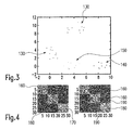
- FIG. 1a, b The detection of a change in position of an object 210 (FIG. 1a, b) is illustrated by means of the representations in FIGS. 3 and 4. It is assumed here that an object generates a set of features whose neighborhood relationships are retained even after a spatial transformation. This also applies if the object 210 has been moved. However, this does not apply if the object 210 does not have a fixed shape, as is the case, for example, with a liquid in a plastic bag.
- the individual points 1-15 represent rays.
- the points x, y given in the aforementioned formula represent points of these rays.
- FIG. 3 shows three clusters 130, 140 representing the features of three objects 200, 210.
- two clusters 130 are shown as undubbed objects 200.
- the associated objects 200 have thus not been moved within the luggage 100 between the recording of the two fluoroscopic images.
- the second object 210 represented by the clusters 140, 150, is shifted between the receptacles of the first and second fluoroscopic images within the item of luggage 100.
- the unshifted cluster 140 represents the position in the first fluoroscopic image and the shifted cluster 150 represents the position of the second object 210 in the second fluoroscopic image.
- FIG. 4 two neighborhood matrices are shown, with the left matrix corresponding to the situation in the fluoroscopic image of the precursor (as in FIG. 1a) and the right matrix of the situation in the fluoroscopy image of the second stage (as in FIG. 1b).
- the left matrix corresponding to the situation in the fluoroscopic image of the precursor (as in FIG. 1a) and the right matrix of the situation in the fluoroscopy image of the second stage (as in FIG. 1b).
- three clusters each belonging to one of the clusters 130, 140 of FIG. 3
- In the left-hand matrix two neighborhood matrices 160 for unshifted objects and a neighborhood matrix 170 for the displaced object 210 are shown, but before the move. Outside the diagonal no further terms can be recognized, so that there are only dark areas. The brighter a section in the matrix, the closer the parameterized points 1-15 of FIG. 2 are to one another.
- the three neighborhood matrices 160, 180 corresponding to each object are unchanged from their counterparts in the left-hand matrix.
- These proximity matrices 190 are seen to be lighter in the right matrix than in the left matrix. This means that the shifted object 210 (this includes the bottom right bright neighborhood matrix 180) has approximated closer to the object that has not changed its position (this includes the middle neighborhood matrix 170).
- the method according to the invention thus makes it possible to detect and analyze movements of individual objects 210 which are located within a suspect region 120. This makes it possible to adapt the examination area within the second-stage device. As a result, in contrast to the previous methods, it is no longer necessary to analyze the entire item of luggage 100 and thus to save a considerable amount of time, which translates into a significantly increased throughput rate.
Landscapes
- Engineering & Computer Science (AREA)
- Physics & Mathematics (AREA)
- General Physics & Mathematics (AREA)
- Theoretical Computer Science (AREA)
- Computer Vision & Pattern Recognition (AREA)
- Multimedia (AREA)
- Quality & Reliability (AREA)
- Analysing Materials By The Use Of Radiation (AREA)
Applications Claiming Priority (1)
| Application Number | Priority Date | Filing Date | Title |
|---|---|---|---|
| DE102004049227A DE102004049227B4 (de) | 2004-10-08 | 2004-10-08 | Verfahren zur Bestimmung der Lageänderung eines Objekts in einem Gepäckstück |
Publications (2)
| Publication Number | Publication Date |
|---|---|
| EP1646009A2 true EP1646009A2 (fr) | 2006-04-12 |
| EP1646009A3 EP1646009A3 (fr) | 2006-08-02 |
Family
ID=35677455
Family Applications (1)
| Application Number | Title | Priority Date | Filing Date |
|---|---|---|---|
| EP05022056A Withdrawn EP1646009A3 (fr) | 2004-10-08 | 2005-10-10 | Procédé de détermination du changement de position d'un objet dans un bagage |
Country Status (3)
| Country | Link |
|---|---|
| US (1) | US7840030B2 (fr) |
| EP (1) | EP1646009A3 (fr) |
| DE (1) | DE102004049227B4 (fr) |
Families Citing this family (9)
| Publication number | Priority date | Publication date | Assignee | Title |
|---|---|---|---|---|
| DE102004049227B4 (de) * | 2004-10-08 | 2007-03-01 | Yxlon International Security Gmbh | Verfahren zur Bestimmung der Lageänderung eines Objekts in einem Gepäckstück |
| DE102005044135B4 (de) * | 2005-09-15 | 2007-07-12 | Yxlon International Security Gmbh | Verfahren zur Bestimmung der Lageänderung eines Objekts innerhalb eines Behälters mittels Röntgenstrahlen |
| US7548606B2 (en) * | 2006-08-31 | 2009-06-16 | Ge Homeland Protection, Inc. | System and method for integrating explosive detection systems |
| US8280145B2 (en) | 2007-02-01 | 2012-10-02 | Kovarik James J | System for non-destructively examining degradation of an interior of a device |
| KR101104609B1 (ko) * | 2007-10-26 | 2012-01-12 | 주식회사 만도 | 차량의 목표주차위치 인식 방법 및 그 시스템 |
| US20100169792A1 (en) * | 2008-12-29 | 2010-07-01 | Seif Ascar | Web and visual content interaction analytics |
| US9091628B2 (en) | 2012-12-21 | 2015-07-28 | L-3 Communications Security And Detection Systems, Inc. | 3D mapping with two orthogonal imaging views |
| US9869647B2 (en) | 2013-12-23 | 2018-01-16 | Johnson Matthey Public Limited Company | Scanning method |
| US10215879B2 (en) * | 2015-05-07 | 2019-02-26 | Morpho Detection, Llc | System for detecting counterfeit goods and method of operating the same |
Family Cites Families (21)
| Publication number | Priority date | Publication date | Assignee | Title |
|---|---|---|---|---|
| IL70214A (en) * | 1983-11-13 | 1987-10-20 | Elscint Ltd | Image contrast enhancement arrangement |
| FR2641867B1 (fr) * | 1989-01-13 | 1991-03-08 | Commissariat Energie Atomique | Procede et dispositif de detection de substances et en particulier d'explosifs, par irradiation neutronique de ceux-ci |
| US5319547A (en) * | 1990-08-10 | 1994-06-07 | Vivid Technologies, Inc. | Device and method for inspection of baggage and other objects |
| US5182764A (en) * | 1991-10-03 | 1993-01-26 | Invision Technologies, Inc. | Automatic concealed object detection system having a pre-scan stage |
| US5367552A (en) * | 1991-10-03 | 1994-11-22 | In Vision Technologies, Inc. | Automatic concealed object detection system having a pre-scan stage |
| US5414474A (en) * | 1992-03-04 | 1995-05-09 | Fujitsu Limited | Moving body recognition apparatus |
| US5293574A (en) * | 1992-10-23 | 1994-03-08 | General Electric Company | Digital x-ray imaging system with automatic tracking |
| DE69532916D1 (de) * | 1994-01-28 | 2004-05-27 | Schneider Medical Technologies | Verfahren und vorrichtung zur bilddarstellung |
| US5712926A (en) * | 1994-10-20 | 1998-01-27 | Eberhard; Jeffrey Wayne | X-ray computed tomography (CT) system for detecting thin objects |
| US5661774A (en) * | 1996-06-27 | 1997-08-26 | Analogic Corporation | Dual energy power supply |
| US6088423A (en) * | 1998-06-05 | 2000-07-11 | Vivid Technologies, Inc. | Multiview x-ray based system for detecting contraband such as in baggage |
| US6411724B1 (en) * | 1999-07-02 | 2002-06-25 | Koninklijke Philips Electronics N.V. | Using meta-descriptors to represent multimedia information |
| DE19959081A1 (de) * | 1999-09-09 | 2001-03-22 | Heimann Systems Gmbh & Co | Verfahren zur Bildverwaltung von Röntgenbildern |
| US6728394B1 (en) * | 2000-02-14 | 2004-04-27 | Siemens Medical Solutions Usa, Inc. | Dynamic measurement of object parameters |
| US20040022436A1 (en) * | 2001-03-16 | 2004-02-05 | Paul Patti | System and method for data analysis of x-ray images |
| EP1597611A1 (fr) * | 2003-02-13 | 2005-11-23 | Philips Intellectual Property & Standards GmbH | Procede et dispositif permettant d'inspecter un objet |
| JP2006518849A (ja) * | 2003-02-24 | 2006-08-17 | コーニンクレッカ フィリップス エレクトロニクス エヌ ヴィ | コンピュータ・トモグラフィを使用することによる自動物質識別 |
| ES2270254T3 (es) * | 2003-10-06 | 2007-04-01 | Yxlon International Security Gmbh | Un procedimiento para determinar el cambio de posicion de una unidad de equipaje para inspeccionar una zona sospechosa en esta unidad de equipaje. |
| US7274811B2 (en) * | 2003-10-31 | 2007-09-25 | Ge Medical Systems Global Technology Company, Llc | Method and apparatus for synchronizing corresponding landmarks among a plurality of images |
| DE10352411B4 (de) * | 2003-11-10 | 2007-02-22 | Yxlon International Security Gmbh | Verfahren zur Entzerrung eines Röntgenbildes eines Gepäckstücks |
| DE102004049227B4 (de) * | 2004-10-08 | 2007-03-01 | Yxlon International Security Gmbh | Verfahren zur Bestimmung der Lageänderung eines Objekts in einem Gepäckstück |
-
2004
- 2004-10-08 DE DE102004049227A patent/DE102004049227B4/de not_active Expired - Fee Related
-
2005
- 2005-10-07 US US11/245,670 patent/US7840030B2/en not_active Expired - Fee Related
- 2005-10-10 EP EP05022056A patent/EP1646009A3/fr not_active Withdrawn
Also Published As
| Publication number | Publication date |
|---|---|
| DE102004049227A1 (de) | 2006-04-20 |
| US7840030B2 (en) | 2010-11-23 |
| DE102004049227B4 (de) | 2007-03-01 |
| US20060078161A1 (en) | 2006-04-13 |
| EP1646009A3 (fr) | 2006-08-02 |
Similar Documents
| Publication | Publication Date | Title |
|---|---|---|
| EP3123208B1 (fr) | Detection des objets dans un recipient | |
| DE10157958B4 (de) | Bildverarbeitungsverfahren und-vorrichtung | |
| DE69630935T2 (de) | Bilverarbeitungsverfahren und -vorrichtung zur automatischen Erfassung von Bereichen eines vorbestimmten Krebstyps in einem Intensitätsbild | |
| EP1522878B1 (fr) | Méthode pour déterminer le changement de position d'un colis pour scruter une région suspecte du colis | |
| DE112008004057T5 (de) | Erkennen verborgener Bedrohungen | |
| DE3505331C2 (de) | Verfahren und Gerät zur Vermessung des bei der Eindringhärteprüfung in einer Probe hinterlassenen Eindrucks | |
| DE102007026803A1 (de) | Verfahren zur Verarbeitung von radiologischen Bildern bei der Tomosynthese zur Erfassung radiologischer Auffälligkeiten | |
| DE102009051826A1 (de) | Verfahren zum Vergleichen der Ähnlichkeit von 3D-bildlichen Objekten | |
| EP3289398B1 (fr) | Procédé de génération d'une image de contraste à réflexion réduite et dispositifs associés | |
| DE102006001681A1 (de) | Verfahren und Vorrichtung zur Darstellung mehrkanaliger Bilddaten | |
| DE112009005018B4 (de) | Trennung zusammengesetzter Objekte | |
| DE10054814A1 (de) | Verfahren und Vorrichtung zur Registrierung von Bildern | |
| DE3921257A1 (de) | Verfahren und vorrichtung zur digitalen analyse von auf stratigraphische daten bezogenen abbildungen | |
| EP1646009A2 (fr) | Procédé de détermination du changement de position d'un objet dans un bagage | |
| DE102007026804A1 (de) | Verfahren zur Verarbeitung von radiologischen Bildern zur Erfassung radiologischer Auffälligkeiten | |
| DE102023104378A1 (de) | Computerimplementiertes Verfahren zur Detektion von Defekten in einem Objekt, das integrierte Schaltkreismuster umfasst, und entsprechendes Computerprogrammprodukt, computerlesbares Medium und System, die solche Verfahren nutzen | |
| EP3853816A1 (fr) | Procédé mis en oeuvre par ordinateur pour la compression de données de mesure provenant d'une mesure d'un volume de mesure | |
| DE102005024949A1 (de) | Verfahren zur Darstellung von Strukturen innerhalb von Volumendatensätzen | |
| AT11770U1 (de) | Verfahren zur auswahl eines optimierten auswerteuntermerkmals zur kontrolle einer freiformfläche und verfahren zur kontrolle einer freiformfläche | |
| DE10045360A1 (de) | Verfahren zur Klassifizierung von Dokumenten | |
| DE112023001617T5 (de) | Verfahren und Vorrichtung zum Online-Training eines Strahlungsbilderkennungsmodells sowie Verfahren und Vorrichtung zur Strahlungsbilderkennung | |
| DE60206927T2 (de) | Verfahren zur verarbeitung von numerischen bildern, insbesondere satellitenbildern | |
| Choudhary et al. | Machine learning for microstructure quantification of different material classes | |
| DE10352411B4 (de) | Verfahren zur Entzerrung eines Röntgenbildes eines Gepäckstücks | |
| DE102005049017A1 (de) | Verfahren zur Segmentierung in einem n-dimensionalen Merkmalsraum und Verfahren zur Klassifikation auf Grundlage von geometrischen Eigenschaften segmentierter Objekte in einem n-dimensionalen Datenraum |
Legal Events
| Date | Code | Title | Description |
|---|---|---|---|
| PUAI | Public reference made under article 153(3) epc to a published international application that has entered the european phase |
Free format text: ORIGINAL CODE: 0009012 |
|
| AK | Designated contracting states |
Kind code of ref document: A2 Designated state(s): AT BE BG CH CY CZ DE DK EE ES FI FR GB GR HU IE IS IT LI LT LU LV MC NL PL PT RO SE SI SK TR |
|
| AX | Request for extension of the european patent |
Extension state: AL BA HR MK YU |
|
| PUAL | Search report despatched |
Free format text: ORIGINAL CODE: 0009013 |
|
| AK | Designated contracting states |
Kind code of ref document: A3 Designated state(s): AT BE BG CH CY CZ DE DK EE ES FI FR GB GR HU IE IS IT LI LT LU LV MC NL PL PT RO SE SI SK TR |
|
| AX | Request for extension of the european patent |
Extension state: AL BA HR MK YU |
|
| 17P | Request for examination filed |
Effective date: 20070202 |
|
| AKX | Designation fees paid |
Designated state(s): AT BE BG CH CY CZ DE DK EE ES FI FR GB GR HU IE IS IT LI LT LU LV MC NL PL PT RO SE SI SK TR |
|
| RAP1 | Party data changed (applicant data changed or rights of an application transferred) |
Owner name: GE HOMELAND PROTECTION, INC. |
|
| 17Q | First examination report despatched |
Effective date: 20090402 |
|
| STAA | Information on the status of an ep patent application or granted ep patent |
Free format text: STATUS: THE APPLICATION IS DEEMED TO BE WITHDRAWN |
|
| 18D | Application deemed to be withdrawn |
Effective date: 20110503 |