EP1646103A1 - Batteriesatz zum elektrischen Motorantrieb von kompakten Motoranlasservorrichtungen, batteriesatzbetriebene Motoranlasservorrichtung und diese enthaltende Vorrichtung - Google Patents
Batteriesatz zum elektrischen Motorantrieb von kompakten Motoranlasservorrichtungen, batteriesatzbetriebene Motoranlasservorrichtung und diese enthaltende Vorrichtung Download PDFInfo
- Publication number
- EP1646103A1 EP1646103A1 EP05256267A EP05256267A EP1646103A1 EP 1646103 A1 EP1646103 A1 EP 1646103A1 EP 05256267 A EP05256267 A EP 05256267A EP 05256267 A EP05256267 A EP 05256267A EP 1646103 A1 EP1646103 A1 EP 1646103A1
- Authority
- EP
- European Patent Office
- Prior art keywords
- engine
- battery pack
- electric motor
- battery
- circuit
- Prior art date
- Legal status (The legal status is an assumption and is not a legal conclusion. Google has not performed a legal analysis and makes no representation as to the accuracy of the status listed.)
- Granted
Links
- WHXSMMKQMYFTQS-UHFFFAOYSA-N Lithium Chemical compound [Li] WHXSMMKQMYFTQS-UHFFFAOYSA-N 0.000 claims abstract description 32
- 229910052744 lithium Inorganic materials 0.000 claims abstract description 32
- 230000007246 mechanism Effects 0.000 claims description 67
- 239000003638 chemical reducing agent Substances 0.000 claims description 22
- 230000015556 catabolic process Effects 0.000 claims description 7
- 238000007599 discharging Methods 0.000 claims description 7
- 230000007774 longterm Effects 0.000 abstract description 3
- 238000003780 insertion Methods 0.000 description 15
- 230000037431 insertion Effects 0.000 description 15
- 230000002093 peripheral effect Effects 0.000 description 13
- 230000009467 reduction Effects 0.000 description 12
- 238000010586 diagram Methods 0.000 description 11
- 239000007858 starting material Substances 0.000 description 11
- 230000001965 increasing effect Effects 0.000 description 8
- 238000004804 winding Methods 0.000 description 8
- 239000000470 constituent Substances 0.000 description 7
- 230000005611 electricity Effects 0.000 description 7
- 239000000446 fuel Substances 0.000 description 7
- 239000003990 capacitor Substances 0.000 description 5
- 238000010521 absorption reaction Methods 0.000 description 4
- 230000035939 shock Effects 0.000 description 4
- 230000004308 accommodation Effects 0.000 description 3
- 238000013461 design Methods 0.000 description 3
- 230000000694 effects Effects 0.000 description 3
- 238000004880 explosion Methods 0.000 description 3
- 229910052987 metal hydride Inorganic materials 0.000 description 3
- 238000000034 method Methods 0.000 description 3
- 229910052759 nickel Inorganic materials 0.000 description 3
- PXHVJJICTQNCMI-UHFFFAOYSA-N nickel Substances [Ni] PXHVJJICTQNCMI-UHFFFAOYSA-N 0.000 description 3
- -1 nickel metal hydride Chemical class 0.000 description 3
- 238000002485 combustion reaction Methods 0.000 description 2
- 238000002474 experimental method Methods 0.000 description 2
- 230000006870 function Effects 0.000 description 2
- 150000002500 ions Chemical class 0.000 description 2
- 230000003446 memory effect Effects 0.000 description 2
- 238000012986 modification Methods 0.000 description 2
- 230000004048 modification Effects 0.000 description 2
- 230000008569 process Effects 0.000 description 2
- 238000004904 shortening Methods 0.000 description 2
- HBBGRARXTFLTSG-UHFFFAOYSA-N Lithium ion Chemical compound [Li+] HBBGRARXTFLTSG-UHFFFAOYSA-N 0.000 description 1
- PWHULOQIROXLJO-UHFFFAOYSA-N Manganese Chemical compound [Mn] PWHULOQIROXLJO-UHFFFAOYSA-N 0.000 description 1
- KLARSDUHONHPRF-UHFFFAOYSA-N [Li].[Mn] Chemical group [Li].[Mn] KLARSDUHONHPRF-UHFFFAOYSA-N 0.000 description 1
- 230000002159 abnormal effect Effects 0.000 description 1
- 238000004891 communication Methods 0.000 description 1
- 230000006835 compression Effects 0.000 description 1
- 238000007906 compression Methods 0.000 description 1
- 238000007796 conventional method Methods 0.000 description 1
- 238000001816 cooling Methods 0.000 description 1
- 230000008878 coupling Effects 0.000 description 1
- 238000010168 coupling process Methods 0.000 description 1
- 238000005859 coupling reaction Methods 0.000 description 1
- 230000001419 dependent effect Effects 0.000 description 1
- 238000009510 drug design Methods 0.000 description 1
- 230000002708 enhancing effect Effects 0.000 description 1
- 230000005284 excitation Effects 0.000 description 1
- 239000007888 film coating Substances 0.000 description 1
- 238000009501 film coating Methods 0.000 description 1
- 238000009499 grossing Methods 0.000 description 1
- 230000006872 improvement Effects 0.000 description 1
- 230000002401 inhibitory effect Effects 0.000 description 1
- 229910001416 lithium ion Inorganic materials 0.000 description 1
- 229910052748 manganese Inorganic materials 0.000 description 1
- 239000011572 manganese Substances 0.000 description 1
- 239000000463 material Substances 0.000 description 1
- 229910052751 metal Inorganic materials 0.000 description 1
- 239000002184 metal Substances 0.000 description 1
- 238000013021 overheating Methods 0.000 description 1
- 238000010248 power generation Methods 0.000 description 1
- 230000000630 rising effect Effects 0.000 description 1
- 238000005507 spraying Methods 0.000 description 1
Images







Classifications
-
- H—ELECTRICITY
- H01—ELECTRIC ELEMENTS
- H01M—PROCESSES OR MEANS, e.g. BATTERIES, FOR THE DIRECT CONVERSION OF CHEMICAL ENERGY INTO ELECTRICAL ENERGY
- H01M10/00—Secondary cells; Manufacture thereof
- H01M10/42—Methods or arrangements for servicing or maintenance of secondary cells or secondary half-cells
- H01M10/425—Structural combination with electronic components, e.g. electronic circuits integrated to the outside of the casing
-
- F—MECHANICAL ENGINEERING; LIGHTING; HEATING; WEAPONS; BLASTING
- F02—COMBUSTION ENGINES; HOT-GAS OR COMBUSTION-PRODUCT ENGINE PLANTS
- F02N—STARTING OF COMBUSTION ENGINES; STARTING AIDS FOR SUCH ENGINES, NOT OTHERWISE PROVIDED FOR
- F02N11/00—Starting of engines by means of electric motors
- F02N11/08—Circuits specially adapted for starting of engines
-
- H—ELECTRICITY
- H01—ELECTRIC ELEMENTS
- H01M—PROCESSES OR MEANS, e.g. BATTERIES, FOR THE DIRECT CONVERSION OF CHEMICAL ENERGY INTO ELECTRICAL ENERGY
- H01M10/00—Secondary cells; Manufacture thereof
- H01M10/42—Methods or arrangements for servicing or maintenance of secondary cells or secondary half-cells
-
- H—ELECTRICITY
- H01—ELECTRIC ELEMENTS
- H01M—PROCESSES OR MEANS, e.g. BATTERIES, FOR THE DIRECT CONVERSION OF CHEMICAL ENERGY INTO ELECTRICAL ENERGY
- H01M50/00—Constructional details or processes of manufacture of the non-active parts of electrochemical cells other than fuel cells, e.g. hybrid cells
- H01M50/20—Mountings; Secondary casings or frames; Racks, modules or packs; Suspension devices; Shock absorbers; Transport or carrying devices; Holders
- H01M50/204—Racks, modules or packs for multiple batteries or multiple cells
-
- H—ELECTRICITY
- H01—ELECTRIC ELEMENTS
- H01M—PROCESSES OR MEANS, e.g. BATTERIES, FOR THE DIRECT CONVERSION OF CHEMICAL ENERGY INTO ELECTRICAL ENERGY
- H01M50/00—Constructional details or processes of manufacture of the non-active parts of electrochemical cells other than fuel cells, e.g. hybrid cells
- H01M50/50—Current conducting connections for cells or batteries
- H01M50/572—Means for preventing undesired use or discharge
- H01M50/574—Devices or arrangements for the interruption of current
-
- F—MECHANICAL ENGINEERING; LIGHTING; HEATING; WEAPONS; BLASTING
- F02—COMBUSTION ENGINES; HOT-GAS OR COMBUSTION-PRODUCT ENGINE PLANTS
- F02N—STARTING OF COMBUSTION ENGINES; STARTING AIDS FOR SUCH ENGINES, NOT OTHERWISE PROVIDED FOR
- F02N11/00—Starting of engines by means of electric motors
- F02N11/08—Circuits specially adapted for starting of engines
- F02N11/0862—Circuits specially adapted for starting of engines characterised by the electrical power supply means, e.g. battery
-
- F—MECHANICAL ENGINEERING; LIGHTING; HEATING; WEAPONS; BLASTING
- F02—COMBUSTION ENGINES; HOT-GAS OR COMBUSTION-PRODUCT ENGINE PLANTS
- F02N—STARTING OF COMBUSTION ENGINES; STARTING AIDS FOR SUCH ENGINES, NOT OTHERWISE PROVIDED FOR
- F02N2300/00—Control related aspects of engine starting
- F02N2300/20—Control related aspects of engine starting characterised by the control method
- F02N2300/2011—Control involving a delay; Control involving a waiting period before engine stop or engine start
-
- H—ELECTRICITY
- H01—ELECTRIC ELEMENTS
- H01M—PROCESSES OR MEANS, e.g. BATTERIES, FOR THE DIRECT CONVERSION OF CHEMICAL ENERGY INTO ELECTRICAL ENERGY
- H01M10/00—Secondary cells; Manufacture thereof
- H01M10/05—Accumulators with non-aqueous electrolyte
- H01M10/052—Li-accumulators
-
- Y—GENERAL TAGGING OF NEW TECHNOLOGICAL DEVELOPMENTS; GENERAL TAGGING OF CROSS-SECTIONAL TECHNOLOGIES SPANNING OVER SEVERAL SECTIONS OF THE IPC; TECHNICAL SUBJECTS COVERED BY FORMER USPC CROSS-REFERENCE ART COLLECTIONS [XRACs] AND DIGESTS
- Y02—TECHNOLOGIES OR APPLICATIONS FOR MITIGATION OR ADAPTATION AGAINST CLIMATE CHANGE
- Y02E—REDUCTION OF GREENHOUSE GAS [GHG] EMISSIONS, RELATED TO ENERGY GENERATION, TRANSMISSION OR DISTRIBUTION
- Y02E60/00—Enabling technologies; Technologies with a potential or indirect contribution to GHG emissions mitigation
- Y02E60/10—Energy storage using batteries
Definitions
- the present invention relates to a battery pack provided therein with a compact battery having large output which drives an ultra-compact electric motor for starting a compact engine mounted in a various working machine such as a carrying harvester, a chain saw, a lawnmower, a piggyback type harvester, a power spraying machine, an engine blower, a duster and a hedge trimmer, an engine starting device driven by a battery pack, and a manual working machine having the engine starting device.
- a carrying harvester a chain saw, a lawnmower, a piggyback type harvester, a power spraying machine, an engine blower, a duster and a hedge trimmer, an engine starting device driven by a battery pack, and a manual working machine having the engine starting device.
- an engine starting device which starts a compact air-cooling type gasoline engine mounted in a manual working machine such as a widely used harvester and chain saw mostly includes a recoil type driving portion, a follower portion connected to a crankshaft of the engine through connecting/disconnecting means such as a centrifugal clutch, and a shock absorption ⁇ power accumulating portion which is disposed between the driving portion and the follower portion and which shock-absorbing driving force of the driving portion and which includes a spiral spring for resiliently accumulate force between the follower portion and the shock absorption power accumulating portion.
- the recoil type driving portion includes a recoil reel around which a recoil rope is wound, and a recoil spiral spring which is disposed between the recoil reel and the casing. Inner and outer ends of the recoil spiral spring are respectively fixed to the recoil reel and the casing.
- the recoil reel is rotated in one direction by manually pulling out the recoil rope and at the same time, the recoil spiral spring is wound up to accumulate a spring force and in this state, if an operator moves his or her hand off the recoil rope, the accumulated force of the recoil spiral spring is released, and the recoil rope is automatically wound back around the recoil reel.
- the recoil type driving portion requires a pulling operation for pulling out the recoil rope whenever the engine is started.
- this pulling operation of the recoil rope it is usually necessary to pull the recoil rope quickly and largely.
- an operator has a weak strength or is an old person, or if the working space is small, the engine cannot be started with one pulling operation in many cases.
- many proposals have been made to facilitate the start of an engine by pulling the recoil rope, and some of them become commercially practical, but complicated properties of the pulling operation itself still remain.
- Significant progress has been made in recent compact electric motor or battery, and although they are extremely reduced in size, they have large capacities.
- the starting device includes a DC motor to which electricity is supplied from a battery and which is driven by the battery, a spiral spring having a spiral spring barrel which is driven and wound by a worm gear fixed to an output shaft of the motor, an output rotation shaft to which an inner end of the spiral spring is fixed, a rotation shaft of an engine connected to the output rotation shaft through a one-way clutch, a turn-lever which stops the rotation of the output rotation shaft or releases the stop, a ganged electric switch which is operated such that it enters only when the rotation stop of the output rotation shaft is released by the lever, and an armature current control circuit which is driven by a motor at the time of switching operation of the electric switch.
- the armature current control circuit keeps rotation of the motor even when the rotation shaft of the motor exceeds a set rotation speed to wind the spiral spring, and when the winding up operation of the spiral spring is completed, if the rotation speed becomes lower than the set rotation speed, electricity supply is cut and the armature current control circuit stops the rotation of the motor.
- Japanese Patent Laid-Open Publication No. 2002-285940 discloses a starter apparatus.
- shock absorption ⁇ force accumulating means is interposed in an intermediate portion of a power transmitting system between a driving portion and a follower portion.
- the driving portion is an electric motor as a driving source.
- a worm connected and fixed to an output rotation shaft of the electric motor and a worm wheel provided on an outer periphery of the spiral spring barrel constitute a speed reducing mechanism.
- This configuration is substantially the same as that of the Japanese Utility Model Laid-Open Publication No. 63-110672.
- a recoil type driving portion is added to the driving side in addition to the electric motor.
- the recoil type driving portion includes a rope reel around which a recoil rope is wound and which is rotated when the recoil rope is pulled, a recoil spiral spring which reversely rotates the rope reel to wind up the recoil rope, and a recoil ratchet mechanism for transmitting the rotation of the rope reel to the shock absorption ⁇ force accumulating means.
- the spiral spring barrel can rotate only in one direction by a one-way clutch. From this configuration, it can be said that the starter of the Japanese Patent Laid-Open Publication No. 2002-285940 is merely a combination of the Japanese Utility Model Laid-Open Publication No. 63-110672 and a known recoil mechanism.
- Japanese Patent Publication No. 2573340 discloses a spiral spring type starting device having a single frame. Accommodated in the frame are a battery, a DC electric motor driven by electricity of the battery, a control apparatus for controlling the operation and the stop of the motor, a highly speed reduction ratio speed reducing mechanism for transmitting power of the motor, a spiral spring force accumulating apparatus which is driven by the highly speed reduction ratio speed reducing mechanism, and a power transmitting apparatus only for transmitting a force of the force accumulating apparatus to the crankshaft.
- the highly speed reduction ratio speed reducing mechanism includes a first planet gear type speed reducer which is driven by a DC electric motor disposed on the other axis which is in parallel to the crankshaft, and a second speed reducer in which a driving gear provided on an output shaft of the planet gear type speed reducer is meshed with a follower gear which is integrally formed on an outer periphery of the spring force accumulating chamber of the force accumulating apparatus.
- a spiral spring barrel is pivotally supported through a support system of a planet gear speed reducer disposed on the opposite side of a crankshaft of an engine such that the spiral spring barrel can rotate in one direction.
- the spiral spring barrel is decelerated and rotated by the planet gear speed reducer connected through a speed reducing spur gear pair including a small gear and a large gear fixed to an output shaft of a DC electric motor disposed in a housing.
- the one-way rotation at that time is carried out by engagement between the ratchet pawl and teeth provided on the outer periphery of the spiral spring barrel.
- An actuating ratchet wheel and an actuating ratchet pawl are disposed on the spiral spring barrel on the side of the crankshaft. When the engagement is released, the ratchet wheel can rotate.
- a starter ratchet wheel is assembled to the actuating ratchet wheel. The starter ratchet wheel engages with a centrifugal clutch pawl provided on the crankshaft.
- the spiral spring barrel is integrally formed at its outer periphery with a ratchet wheel.
- a ratchet wheel having a small diameter meshes with an upper end of the spiral spring barrel.
- the rotation shaft fixed to the ratchet wheel having the small diameter can be rotated from outside using a manual crank.
- the manual crank is not inserted during a normal operation of the engine, and the ratchet wheel having the small diameter idles. If the starting operation ends in failure and attempt is made to insert the spiral spring again, the manual crank is inserted into the rotation shaft of the ratchet wheel having the small diameter, the spiral spring barrel is rotated, and force is accumulated in the spiral spring.
- the actuating ratchet is operated to release the energy accumulated in the spiral spring, thereby rotating the starter ratchet wheel to crank and start the engine.
- the battery used as a power supply of a starting device of an engine disclosed in Japanese Utility Model Laid-Open Publication No. 63-110672, Japanese Patent Laid-Open Publication No. 2002-285940, Japanese Patent Publication No. 2573340 and Japanese Utility Model Laid-Open Publication No. 2-13171 is a battery so-called NiCad battery or nickel metal hydride battery, and an accommodation space of the battery is not specified as described above.
- such battery is disposed in the starting device in many cases as described in Japanese Patent Publication No. 2573340 and Japanese Utility Model Laid-Open Publication No. 2-13171, and if not, the entire capacity of the conventional battery is increased and thus, the battery is disposed in its special space in the vicinity of the starting device in many cases.
- the spiral spring barrel is rotated in one direction by the meshing state between the worm gear which is directly coupled to the electric motor and the worm wheel formed on the outer periphery of the spiral spring barrel. Therefore, the spiral spring barrel does not reversely rotate, but in a power transmitting mechanism using the meshing state between the worm gear and the worm wheel, the direction of the output shaft of the electric motor and the rotation driving shaft of the spiral spring barrel intersect with each other at right angles, the efficiency is poor (about 60%) and the device cannot be reduced in size in terms of design. According to the engine starting device of the Japanese Utility Model Laid-Open Publication No. 63-110672, when the battery goes dead or the electric motor is broken, the engine starting device itself cannot be operated.
- the spiral spring barrel is manually driven at the time of emergency by the recoil type drive mechanism, the entire apparatus corresponds to an apparatus in which the speed reducing mechanism is added to the conventional recoil type engine starting device as the electric motor, and since the speed reducing mechanism includes the worm and the worm wheel of the spiral spring barrel, the shaft of the electric motor and the support shaft of the spiral spring barrel is needed to intersect with each other at right angles, and it is difficult to reduce the entire apparatus in size.
- the highly speed reduction ratio speed reducing mechanism is disposed between the electric motor and the spiral spring barrel, the motor capacity and the battery capacity are reduced in size to 1/10 and 1/6 as compared with the self starter type battery, this is practical even if a storage battery is provided, but the speed reduction ratio is set extremely large as large as 1/250 to 1/300. Thus, it takes a long time until the spiral spring barrel is rotated to obtain a predetermined force in the spiral spring.
- an automatic winding control apparatus for the spiral spring is disposed, force accumulating operation of the force accumulating spring is automatically carried out whenever the starting operation is carried out once by the control circuit of the control apparatus, the timer or the winding up operation of the spiral spring is detected, the electricity to the motor is stopped, thereby reducing the waiting time at the time of the restarting operation.
- the entire apparatus becomes complicated, and its cost is naturally increased.
- the present applicant previously proposed an electric engine starting device in Japanese Patent Application No. 2004-232139 in which unnecessary members are eliminated, the engine starting device is ultimately reduced in size and weight under rational design, and an engine can be started manually at the time of emergency.
- the engine starting device includes a compact electric motor driven by a battery, a power accumulating portion in which power of the compact electric motor is transmitted in a power accumulating direction through a highly speed reducer mechanism, and a power transmitting portion for transmitting the accumulated force of the power accumulating portion to a crankshaft of the engine, the engine starting device further including a spring and a rotation support member which supports one end of the spring, a spiral spring or a coil spring can be used as the spring, when the spring is the spiral spring, the rotation support member includes the spiral spring barrel, and if the spring is the coil spring, a normal gear can be used.
- the support member is formed with a first gear
- a second gear is fixed to the output shaft of the highly speed reducer mechanism
- the first and second gears mesh with each other
- the engine starting device further includes rotation preventing means in which the power accumulating portion or the power transmitting portion is disposed, the power accumulating portion or the power transmitting portion is allowed to rotate in a accumulated force releasing direction in a normal state, but when the electric motor is in its inoperative state, the rotation in the accumulated force releasing direction is prevented
- the engine starting device further includes a rotation operating mechanism which is disposed on an axis of the output shaft of the highly speed reducer mechanism, which can be engaged with and disengaged from a shaft end of the output shaft, and which can rotate the output shaft manually.
- the highly speed reducer mechanism is a planet gear type speed reducing mechanism, the rotation axes of the power accumulating portion and the power transmitting portion are disposed on the same axis of the crankshaft, the rotation shafts of the compact electric motor and the highly speed reducer mechanism are disposed in parallel to the crankshaft, and spur gears are used as the first and second gears.
- the NiCad battery or nickel metal hydride battery are widely used as described above.
- a standard compact battery has usually 1.2 V. In order to drive an engine starting compact electric motor, at least 7.2 V is required. Thus, the compact electric motor can be driven if six batteries are used theoretically.
- the object is effectively achieved by providing a battery pack for driving a compact electric motor of a compact engine starting device mounted on a working machine comprising a compact electric motor, a power accumulating portion in which power of the compact electric motor is transmitted in a power accumulating direction through a highly speed reducer mechanism, and a power transmitting portion for transmitting accumulated force of the power accumulating portion to a crankshaft of an engine, wherein the battery pack is provided therein with a lithium-based secondary battery comprising at least two cells, a normal self-discharge preventing circuit, an overcurrent preventing circuit and a protection circuit comprising an electronic circuit such as an overcharge preventing circuit, an overdischarge inhibit circuit and a start switch relay circuit, which are connected to the lithium-based secondary battery.
- the overdischarge inhibit circuit is a time circuit, and a continuous discharge time required for driving the engine starting electric motor is set such that the continuous discharge time is automatically stopped when 5 to 15 seconds elapsed.
- total discharging amount of the lithium-based secondary battery in the battery pack is 500 to 2000 mAh, and discharge voltage per one cell is 3.0 to 4.2 V.
- maximum discharge current of the lithium-based secondary battery in the battery pack is set to 10 to 60 A, and discharge is automatically stopped when a predetermined continuous discharge time set in accordance with set maximum discharge current elapsed.
- the battery pack has a volume of 2.5 x 10 4 to 1.0 ⁇ 10 5 mm 3 .
- the overcharge preventing circuit cuts a discharge when a discharge voltage per one cell exceeds 4.0 to 4.4 V.
- the battery pack further comprises an overheat preventing circuit in which the protection circuit detects internal temperature of the battery pack, and at a time when a rise of the detected temperature reaches a predetermined temperature irrespective of a set discharge time region of the overdischarge inhibit circuit, an electronic switch is automatically opened.
- an overheat preventing circuit in which the protection circuit detects internal temperature of the battery pack, and at a time when a rise of the detected temperature reaches a predetermined temperature irrespective of a set discharge time region of the overdischarge inhibit circuit, an electronic switch is automatically opened.
- the starting device of a compact engine is provided therein with a compact electric motor driven by a lithium-based secondary battery of the battery pack, a power accumulating portion in which the power of the compact electric motor is transmitted in a power accumulating direction through a highly speed reducer mechanism, and a power transmitting portion for transmitting the accumulated force of the power accumulating portion to a crankshaft of the engine.
- the battery pack is integrally disposed in a switch box of a steering of the manual working machine.
- the compact electric motor has a housing volume of 4.0 ⁇ 10 3 to 8.0 ⁇ 10 4 mm 3 , breakdown current of 1 to 100 A, and breakdown torque of 10 to 500 mNm.
- the starting device further comprises a carburetor having an automatic choke operated by a solenoid valve which is driven by the lithium-based secondary battery, and drive current of the solenoid valve is 200 to 800 mA.
- the engine comprises a power generator for charging the lithium secondary battery
- the power generator comprises a magnet disposed on a rotation portion of the engine, and a power generating coil disposed on an opposed portion of the magnet.
- the rotation portion of the engine is a fan fixed to the crankshaft.
- a lithium-based secondary battery which can be most reduced in size which is much inferior to other dry batteries in terms of performance is employed as a battery.
- the entire capacity as a power supply only need to have discharge capacity required for driving engine starting electric motor, driving the protection circuit of the battery, driving a solenoid valve of the carburetor having a later-described automatic choke, and for the electronic circuit.
- the necessary discharge capacity is 1000 mAh.
- An output voltage of one cell is 3.8 V, if two cells are used, the voltage is 7.6 V, and even if the discharge current with respect to the electric motor for starting the engine is set to 10 to 60 A, this is sufficient capacity as a power supply for driving others.
- the lithium-based secondary battery of the invention which becomes a power supply of a compact engine starting device mounted on a working machine has sufficient capacity for starting the engine, its volume is extremely small, and even if the battery is incorporated in the starting device, the starting device can be compact incomparable with conventional technique.
- the internal impedance of the lithium-based secondary battery is extremely low as low as 1/30 of conventional dry battery, and weight energy density and volume energy density are 2 to 3 times of those of the conventional dry battery, and this is suitable reducing the weight and size.
- a lithium-based ion secondary battery does not include environmentally harmful material, it does not have memory effect unlike NiCad battery, self-discharge is small, and necessary capacity is maintained for a long term.
- safety is secured by various protection circuits, high output can be obtained and thus, it is preferable that the battery is a manganese lithium-based ion secondary battery.
- a rate value called high rate in this kind of lithium-based secondary battery is usually 3 to 5C, but in this invention, a lithium-based secondary battery having the rate value of 26C or higher which can discharge 26A or higher with 1000 mAh discharge capacity is used.
- this invention includes a special overdischarge inhibit circuit in which a discharge time required for driving the engine starting electric motor is set, and after this set time elapsed, the driving of the electric motor is automatically stopped. Since the overdischarge inhibit circuit is included, overheat of the electric motor driving circuit which has the greatest power consumption is prevented, and the battery life can be increased.
- the overdischarge inhibit circuit not only prevents the overheat of the electric motor driving circuit, but also suppress the overheat of elements disposed in various circuits, and burnout and ignition of various circuits can be prevented.
- a conventionally known so-called time circuit and electronic switch may be incorporated in the same circuit. According to the time circuit and electronic switch, time required for starting the engine after the electric motor is started is preset, and the electric motor is automatically stopped after the preset time elapsed.
- Appropriate time region required for starting the engine after the electric motor is started is 5 to 15 seconds.
- the overheat preventing circuit is provided.
- the temperature in the battery is detected, and in this time region of course, and even if in this time region, if the temperature rise exceeds 10°C, the electronic switch is closed.
- the overdischarge inhibit circuit in addition to the above function, even when the electric motor is brought into a stall state in which the rotation thereof is stopped even when current is supplied due to any reason, since the discharge is stopped in the above time region, the electric motor is not seized up, and durability thereof is enhanced.
- the volume of the battery pack employed in the invention is 5.5 x 10 4 to 1.0 ⁇ 10 5 mm 3 , and the weight thereof is about 80 g, and the battery pack is extremely small and light. Since the battery pack is extremely small and light, the battery pack can be incorporated directly in a case of the engine starting device, but the battery pack can also be accommodated in the switch box of the steering wheel in the working machine for example. When the battery pack is accommodated in the switch box, since the battery pack is away from the engine, there are effects in terms of resistance to vibration and heat resistance, and since the battery pack is away from a gasoline tank, safety is secured, and the battery can easily be exchanged.
- the recoil type drive mechanism can be eliminated by the Japanese Patent Application No. 2004-232139, the outer size of the starting device can be reduced extremely, and its weight can also be reduced.
- the battery and the starting switch are not mounted in the starting device and are disposed in the switch box of the steering wheel of the working machine.
- a first axes of rotation support shafts of the power accumulating portion and the power transmitting portion of the engine starting device and second axes of the rotation shafts of the electric motor and the highly speed reducer mechanism are arranged in parallel to each other, and the first and second axes are disposed on the same plane.
- the plane including the second axis and the first axis of the engine is a vertical surface.
- the planet gear type speed reducing mechanism When the planet gear type speed reducing mechanism is employed as the highly speed reducer mechanism, it is easy to reduce the mechanism in size, its speed reduction ratio is not as high as 1/250 to 1/300 as described in the Japanese Patent Laid-Open Publication No. 2002-285940 when the lithium-based secondary battery having high output is employed as the battery and the compact electric motor having high torque is employed, and sufficient effect can be obtained even if the speed reduction ratio is as low as about 1/50, and the starting time of the engine, i.e. , time required until the power accumulating portion can accumulate predetermined force can largely be reduced.
- the starting compact electric motor has capacity and torque sufficient for winding up the spiral spring which is a force accumulating apparatus because the speed reducing mechanism including the planet gears are interposed although the housing volume is as small as 4.0 ⁇ 10 3 to 8.0 ⁇ 10 4 mm 3 .
- the starting electric motor is driven when the temperature of the engine is equal to or lower than a predetermined temperature, the solenoid valve is energized by the battery, the air/fuel ratio is changed, the fuel content is increased to an appropriate value.
- the engine of the working machine having the engine starting device of the above configuration and characteristics is provided, battery exhaustion is not caused, necessary discharge can always be carried out at the time of start of the engine, and the engine can smoothly start.
- the lithium-based secondary battery employed in the invention is put on charge using the power generator, there is a tendency that if the resistance in the battery is abruptly increased if the discharge voltage exceeds 4.0 to 4.4 V, and the recovering ratio of the capacity is largely reduced.
- the battery pack is provided with a special overcharge preventing circuit, overcharge is prevented to increase the lifetime of the battery.
- a rotation portion of the engine on which the magnet for the power generator is provided is a portion of a peripheral surface of a fan fixed to the crankshaft which always rotates together with the start of the engine, the power generation is started from the start of the engine, and it is only necessary to provide a coil, it is unnecessary to increase the conventional engine case itself in size.
- the effects which the present invention exerts are considerably great.
- Fig. 1 is a diagram of a starting-circuit of a hybrid self-starter of a compact engine mounted in a working machine of the invention.
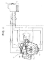
- Fig. 2 is a perspective view showing a concrete wiring between the compact engine and a battery accommodated in a switch box added to a steering wheel of the working machine.
- the compact engine 10 of the embodiment includes a cylinder 11, a spark plug 12 facing a combustion chamber of the cylinder 11, a piston (not shown), a crankshaft (not shown), a fan 13 fixed to the crankshaft, and a centrifugal clutch (not shown) disposed on the back side (front side in Fig. 2) of the fan 13.
- the compact engine 10 of the embodiment further includes, in addition to the above constituent members, a power generator 14 for discharging a later-described battery which is a power supply for driving an engine starting electric motor 131, and a carburetor 15 having an automatic choke for adjusting an air/fuel ratio when the engine is to be started.
- the power generator 14 includes a first magnet 13a fixed to a portion of a peripheral surface of the fan 13, and a discharge coil 14a opposed to a rotation surface of the magnet 13a.
- a solenoid valve (not shown) is mounted on the carburetor 15 having the automatic choke.
- the solenoid valve is not energized by the choke coil 15b when the engine is stopped, and is closed, but current flows from a battery pack 16 to the choke coil 15b at the same time when a starting switch is operated at the time of start of the engine to open the solenoid valve.
- the opening and closing amount of the solenoid valve controls the air/fuel ratio.
- a temperature sensor (not shown) is disposed in the vicinity of an explosion chamber of the engine, and the opening of the valve is controlled based on the detected temperature of the sensor.
- various electric or electronic devices disposed in the engine 10 such as the engine starting electric motor 131 are driven or operated by a single battery.
- a lithium-based secondary battery as the battery.
- the lithium-based secondary battery is small in size and weight as described above, the output voltage of a single compact cell is three or more times of a conventional NiCad battery, and even if the shallow charge and discharge are repeated like the self-starter system as in this invention, since there is no memory effect in which the capacity is reduced, even if the battery is left for a long term, the battery can smoothly start the engine.
- the lithium-based secondary battery has extremely small self-discharge amount as small as 1/5 of the NiCad battery, and especially the internal resistance is low as compared with other dry batteries including the NiCad battery. It is preferable that a manganese-based lithium ion battery having high safety and capable of discharging high output is employed.
- two cells of lithium-based secondary batteries are used as one set.
- the output voltage of one cell is about 4.2 V
- discharge capacity is 1000 mAh
- its rate value is extremely high as high as 26C.
- the volume the battery pack 16 is as small as 2.5 x 10 4 mm 3 , and its weight is only about 70 g.
- the compact electric motor 131 used in the embodiment has extremely small housing volume of 2.0 x 10 4 mm 3 , and breakdown current is 1 to 100 A, and breakdown torque is as wide as 100 mNm. To drive the starting electric motor 131, power supply of about 7.6 to 8.0 V or higher is required. Thus, two cells are used as the batteries for starting engine.
- the battery of the embodiment includes a single packed battery including the lithium-based secondary battery having two cells and various electronic circuits.
- the electronic circuits include a later-described battery protection circuit, a battery charging circuit and various circuits for driving the engine.
- the rate of the lithium-based secondary battery is high.
- the total discharge capacity is set to 1000 mAh
- the driving current of the starting electric motor 131 is set to 26 A.
- the packed battery of the embodiment is extremely thin and thus, the battery pack 16 may be incorporated in a case of the starting device, but in this embodiment, the battery is detachably accommodated in the switch box 17 mounted on the steering wheel of the working machine as will be described later.
- the various electric devices of the engine 10 and the battery pack 16 are connected through a plurality of lead wires connected to first and second connectors 19a and 19b of a connector 19.
- Fig. 3 shows the part of the connection circuit schematically.
- a starting switch 20 if a starting switch 20 is turned ON, electricity is discharged to the starting electric motor 131 through the overdischarge inhibit circuit A which is one of the battery protection circuits, and the engine starting electric motor 131 is driven.
- a temperature sensor (not shown) detects that the temperature around the explosion chamber of the engine is lower than a predetermined temperature, an air/fuel ratio control circuit is operated, current flows to the choke coil 15b of the carburetor 15 having the automatic choke, the solenoid valve (not shown) disposed in an intake passage of the carburetor 15a is opened, and the fuel supplied to the compact engine 10 is increased.
- the overdischarge inhibit circuit A is one of the most characterized configurations of the present invention, and its basic functions are to previously set sufficient time required for reliably starting the compact engine 10 by driving the engine starting electric motor 131, to automatically shut down the driving circuit of the engine starting electric motor 131 when the preset time elapsed after the engine starting electric motor 131 is actuated, and to stop the operation of the engine starting electric motor 131.
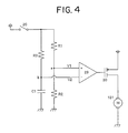
- Fig. 4 shows one example of a typical time circuit using a capacitor constituting the overdischarge inhibit circuit A.
- the overdischarge inhibit circuit A is not limited to the time circuit shown in Fig. 4. Meanwhile both the overdischarge inhibit circuit and the overheat preventing circuit can be disposed.
- the overheat preventing circuit detects the internal temperature of the battery pack 16 for example, automatically opens the circuit when the detected value exceeds a preset temperature to shut down the discharge, or integrates current value flowing through the starting electric motor 131 with respect to driving time, converts the value into an amount of heat, and automatically shuts down the discharge when the amount of heat exceeds a set value, or automatically shuts down the discharge when the number of revolutions of the motor exceeds a preset value.
- the driving continuation time T of the electric motor 131 is set to 10 seconds. If the electric motor 131 is stalled and the starting switch 20 is turned ON and current of 26 A flows from the battery pack 16 to the motor driving circuit, the internal circuit of the battery pack 16 is overheated, and a portion of the circuit element is burned out and the circuit is destroyed. If the winding temperature exceeds a certain value, the electric motor 131 is also burned out and the motor does not rotate smoothly. Figs. 5 and 6 show results of the experiment.
- a relay circuit which is one of characterizing portion of the present invention is incorporated in the battery pack.
- Fig. 7 shows the relay circuit.
- the relay circuit of the invention protects the starting switch.
- the circuit is not of excitation type and includes a transistor circuit and is extremely small in size.
- the resistance of a transistor 29 becomes infinite while the starting switch 20 is opened, current does not flow to the circuit, and the time circuit which is the overdischarge inhibit circuit A is not in its operative state. Of course, driving current does not flow to the electric motor M either. If the starting switch 20 is turned ON, current discharged from the battery is divided into large current on the side of the electric motor M and very small current on the side of the discharge inhibit circuit A through a transistor 30. At that time, current flowing to the overdischarge inhibit circuit A is extremely low and is about 5 mA, and remaining large current flows to the electric motor M.
- the capacitor C of the overdischarge inhibit circuit A starts charging at the same time, and if time determined by the capacity of the capacitor C elapsed, a signal is sent to a switching circuit (not shown), the switching circuit is opened to stop the discharge of the battery.
- the discharge time is set to 5 to 10 seconds due to the later-described reason.
- Fig. 8 and Table 1 show characteristics of current - time - temperature in a battery circuit when the various circuits were disposed and the same experiment was carried out. According to Fig. 8, it can be found that there is a straight correlation of the same gradient between the load current and the temperature in the battery circuit with time. According to the embodiment, since the discharge current immediately after the starting switch 20 is turned ON is 26 A, it can be estimated that the temperature rise at that time is 8.8°C and time required until the temperature reaches the rise temperature is 9.8 seconds from Fig. 8. [Table 1] Battery: 7.4 V, 1000 mAh Time (sec) Load current (A) Temperature (°C) 14 20 7 12.6 22 7.6 11.2 24 8.2 9.8 26 8.8 8.4 28 9.4 7 30 10
- the temperature in the vicinity of the battery box in direct sunlight in midsummer is about 60°C in some cases, and the heat resistant upper limit is 70°C.
- the discharge time is set to 5 to 10 seconds.
- the discharge time is set to 5 to 15 seconds which does not give an operator abnormal feeling and which is the starting time of the engine while taking safety in consideration.
- an overcharge preventing circuit B of the battery and an overcurrent preventing circuit are incorporated in addition to the overdischarge inhibit circuit A.
- a charging circuit (not shown) and an ignition circuit of the engine are also incorporated in the battery pack 16. Since the overcharge preventing circuit B, the charging circuit (not shown) and the ignition circuit of the engine are known circuits, detailed explanation thereof will be omitted here.
- the overcurrent preventing circuit is not illustrated in the drawing, but the overcurrent preventing circuit is provided in an intermediate portion of a necessary wire among wires of the various circuits. In this embodiment, the upper limit current of shut down of the overcurrent preventing circuit is about 30 A.
- the power generator 14 keeps generating power through the overcharge preventing circuit B, its AC electricity is smoothened through a smoothing circuit, and is sent to the battery pack 16, thereby charging the battery pack 16. If the discharge voltage at that time exceeds 4.1 V, the internal resistance rate of the lithium-based secondary battery abruptly increases as shown in Fig. 10, and the capacity recovering rate is abruptly lowered. Therefore, in this embodiment, it is adjusted by the overcharge preventing circuit incorporated in the battery pack, and the discharge voltage is suppressed to about 8.1 V.
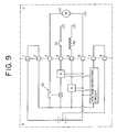
- FIG. 9 is a block diagram of a circuit when the discharge of the internal circuits of the battery pack 16 is inhibited. This drawing is the entire block diagram when the overdischarge inhibit circuit A and the overcharge preventing circuit B of the internal circuits of the battery pack 16 are shown as representative circuits. In the drawing, the right side block C shown with phantom line shows an external wire, and the left block D shows an internal wire of the battery pack 16 of the invention.
- the closed-circuit formed by the input and output terminals 1, 2, 7 and 8 is a circuit required for avoiding the electric motor driving circuit of the battery pack 16 and the self-discharge of the protection circuit.
- the input and output terminals 3 to 6 are terminals for connecting the charging circuit B and the electric motor driving circuit including the overdischarge inhibit circuit A to the external wire.
- the battery pack 16 is mounted in the switch box 17 so that the all of the internal circuits are electrically connected to each other and the circuits can be operated by the battery. If the battery pack 16 is removed from the switch box 17, discharge from the battery is only the self-discharge of the battery itself, and the lifetime of the battery can be increased.
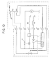
- Fig. 10 shows an example in which at the same time when an engine stop switch 23 is turned off no matter whether the engine is operating or not, all of the closed-circuits and opened-circuits incorporated in the battery pack 16 are shut down. That is, in the drawing, connection and opening can be done through four input and output terminals 1, 2, 7, 8 and the switches 31 and 32, and the switches 31 and 32 are formed so as to operate in association with the operation of the engine stop switch 23.
- the engine stop switch 23 is ON, it is not connected to the spark plug 12, and the switches 31 and 32 between the starting switch 20 and the input and output terminals 1, 2, 7, 8 are also opened.
- the starting switch 20 and the engine stop switch 23 are closed in this state, the electric motor 131 is charged from the battery, and the engine 10 starts. At the same time, the battery and the spark plug 12 are connected to each other, and the engine 10 keeps rotating.
- the engine stop switch 23 is turned OFF, a KILL terminal of the coil 12a of the ignition circuit is grounded to stop the engine.
- the two switches 31 and 32 disposed between the input and output terminals 1, 2, 7, 8 are disconnected. If the switches 31 and 32 are opened, all of the internal circuits of the battery pack 16 are shut down independently.
- Fig. 12 shows an assembly of an engine starting device 100 and a compact engine 10 according to the embodiment of the invention having the connection circuit.
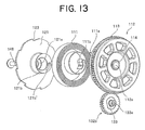
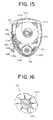
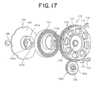
- Figs. 12 to 15 are explanatory views showing disposition and configuration of the constituent devices of the engine starting device 100 of the embodiment.
- the engine starting device 100 of the embodiment is applied to a compact air-cooled gasoline engine and the like, and the engine starting device 100 is disposed near an input and output terminal of the crankshaft 25 of an internal combustion engine 10.
- the engine starting device 100 includes a power accumulating portion 110, a power transmitting portion 120 and an electric driving portion 130. These power accumulating portion 110 , the power transmitting portion 120 and the electric driving portion 130 are assembled as one unit and accommodated in a single case 140.
- the case 140 has an upper half square first space A for accommodating the power accumulating portion 110 and the power transmitting portion 120, and a lower half second space B for accommodating the driving portion 130.
- the second space B is of a reversed triangular shape whose width is gradually reduced toward its lower end.
- the case 140 is of a half-cut structure including an engine side and a side opposite of the engine, and includes first and second case bodies 140a and 140b.
- the upper half of the first case body 140a on the side of the engine is a substantially square window portion 141, and a speed reducing mechanism fitting insertion hole 142 is formed in a central portion of its lower half.
- a later-described highly speed reducer mechanism 132 which is one of the constituent members of the electric driving portion 130 is fitted, inserted and supported in the speed reducing mechanism fitting insertion hole 142.
- Bolt insertion holes 143 are formed in four corners inside the square window portion 141 for fixing the first case body 140a to the engine 10.
- Screw holes 144 are formed in lower portions of upper two corners and lower two corners of the frame of the square window portion 141 for coupling the second case body 140b.
- a shaft 145 projects toward the engine from a central portion of a bottom inner wall surface forming the first space A of the second case body 140b on the opposite side of the engine.
- a wrench insertion hole 146 which is in communication with an internal space is formed at a portion of the back wall forming the second space B vertically below the shaft 145 corresponding to a center of the speed reducing mechanism fitting insertion hole 142.
- Bolt insertion holes 147 are also formed in the second case body 140b corresponding to the screw holes 144 of the first case body 140a.
- the power accumulating portion 110 includes a spiral spring 111 and a spiral spring barrel 112.
- a spur gear 113 which is continuous in the circumferential direction, is formed on a half of an outer peripheral surface of the spiral spring barrel 112.
- a through hole 112a is formed in a central portion of the spiral spring barrel 112, an outer ring of a bearing-shaped one-way clutch 114 embedded into the through hole 112a, and the shaft 145 of the second case body 140b is press-fitted into the inner ring of the one-way clutch 114.
- a spiral spring accommodation space (not shown) is formed in the spiral spring barrel 112 on the side of the engine, and an outer end fixing groove (not shown) for engaging and fixing the outer end 111a of the spiral spring 111 is formed in a portion of a peripheral wall of the spiral spring accommodating space.
- the spiral spring barrel 112 is allowed to rotate only in one direction by the bearing type one-way clutch 114.
- ratchet teeth 115 which are different from the spur gear 113 may be formed on the outer peripheral surface of the spiral spring barrel 112 instead of the one-way clutch 114 as shown in Fig. 16, and a ratchet pawl 116 which engages with the ratchet teeth 115 may rotatably supported by a portion of the second case body 140b.
- the spiral spring barrel 112 is also allowed to rotate only in one direction.
- the ratchet pawl 116 is biased in a direction engaging with the ratchet teeth 115 by the spring member 117 mounted on the second case body 140b.
- the spiral spring barrel 112 is rotatably supported by the shaft 145 through a normal plain bearing 118.
- Figs. 13 to 16 show a portion of Fig. 9 in an enlarged manner.
- the power transmitting portion 120 includes an actuation pulley 121 and an engaging and disengaging member 122 which is engaged with and disengaged from the actuation pulley 121.
- a loose insertion hole 121a is formed in a center of the actuation pulley 121.
- the shaft 145 projecting from the second case body 140b can loosely be inserted into the loose insertion hole 121a.
- a spiral spring end fixing portion 121b is formed on a center of the actuation pulley 121 on the opposite side of the engine.
- the spiral spring end fixing portion 121b projects toward the spiral spring barrel 112 such as to surround the loose insertion hole 121a.
- the spiral spring end fixing portion 121b is formed with an inner end fixing groove 121b, which is engaged and fixed to the inner end 111b of the spiral spring 111.
- a screw hole (not shown) is formed in a tip end of the shaft 145.
- the engaging projection 121c engages with an engaging pawl 26, which is one element of the centrifugal clutch mechanism mounted on the crankshaft 25 of the engine 10.
- the engaging projection 121c engaged with the engaging pawl 26 mounted on the crankshaft 25 and stops while receiving energy in a releasing direction generated in a process in which the spiral spring barrel 112 rotates and the spring force is accumulated in the spiral spring 111 until the energy exceeds the maximum load of the engine, but if the force accumulated in the spiral spring 111 exceeds the maximum load, the engaging projection 121c starts rotating together with the engaged engaging pawl 26 to start the engine. If the engine rotation is brought into the steady state, the engagement between the engaging pawl 26 and the engaging projection 121c of the actuation pulley 121 is released by the centrifugal force, and the rotation of the engine is continued.
- Ratchet teeth 123 are formed on the outer periphery of the actuation pulley 121 at predetermined distances from one another, and the entire actuation pulley 121 constitutes the ratchet wheel.
- One end 122b of the engaging and disengaging member 122 is rotatably supported by a boss 140a-1 of the first case body 140a, the tip end 122a is turned by a push button 149 and the tip end 122a is brought into engagement with and disengagement from the outer periphery ratchet teeth 123 of the actuation pulley 121 so as to allow or inhibit the rotation of the actuation pulley 121.
- the tip end 122a of the engaging and disengaging member 122 is biased by a torsion spring 150 in a direction where the tip end 122a is disengaged from the ratchet teeth 123 at the time of normal start of the engine, the one end 122b is rotated against the biasing force of the torsion spring 150, and the tip end 122a can be engaged with the ratchet teeth 123 for the first time.
- the engaging and disengaging member 122 and the ratchet teeth 123 of the actuation pulley 121 correspond to rotation prohibiting inhibiting means of the present invention.
- a ball portion 149a of a pin tip end of the push button 149 mounted on a portion of the peripheral wall of the first case body 140a is fitted into the tip end 122a of the engaging and disengaging member 122, and if the push button 149 is pushed, the engaging and disengaging member 122 is turned toward the ratchet teeth 123 against the biasing force of the torsion spring 150.
- the push button 149 is locked by locking means (not shown), and if the push button 149 is pulled toward the operator, the push button 149 is unlocked, and the engaging and disengaging member 122 is turned in a direction where the engagement with respect to the ratchet teeth 123 is released.
- the engaging and disengaging member 122 is fixed to the peripheral wall of the first case body 140a by the biasing force of the torsion spring 150.
- the electric driving portion 130 includes the starting electric motor 131 and the highly speed reducer mechanism 132 coupled to the output shaft of the electric motor 131.
- the high speed rotation of the electric motor 131 is decelerated through the highly speed reducer mechanism 132, and transmitted to the spiral spring barrel 112.
- the highly speed reducer mechanism 132 includes a compact planet gear mechanism 132a and a spur gear 132b fixed to the output shaft of the planet gear mechanism 132a. Since a combination of the planet gear mechanism 132a and the spur gear 132b is employed as the speed reducing mechanism 132, its input portion and the output shaft can be disposed on the same axis, and the axis can be disposed in parallel to the shaft 145 which projects from the second case body 140b toward the engine.
- the axis of the electric driving portion 130 is disposed substantially vertically below the shaft 145.
- the recoil mechanism is eliminated in the present invention, the battery which is conventionally disposed below the power accumulating portion 110 and the power transmitting portion 120 is disposed in the switch box 17 (see Fig. 3) mounted on the steering wheel (not shown) of a working machine for example outside of the case, the electric driving portion 130 is disposed in the vacant space, thereby shortening the length of the case 140 in the axial direction and shortening the lateral width of the case 140 to its minimum value.
- the planet gear mechanism 132a of the embodiment includes first to third internal gears 132a-1 to 132a-3, which are ring-shaped sun gears.
- the planet gear mechanism 132a is accommodated and fixed in the motor drive accommodating case 134 together with the electric motor 131. That is, a plurality of projections 132a'-1 to 132a'-3 extending in parallel to the rotation shaft project from outer peripheral surface of the first to third internal gears 132a-1 to 132a-3, and the same number of fitting grooves 134a-1 extending in parallel to the axis are formed in the inner peripheral surface of the motor drive accommodating case 134 at corresponding positions of the projections 132a'-1 to 132a'-3.
- the projections 132a'-1 to 132a'-3 are fitted into the fitting grooves 134a-1.
- the motor drive accommodating case 134 includes a bottomed cylindrical body, and a side thereof opposite of the engine is opened.
- the motor drive accommodating case 134 is divided into a cylindrical body 134a and a bottom portion 134b.
- Projections 134c and 134d extending in parallel to the axis project from both portions of the outer periphery formed with the fitting grooves 134a-1 of the cylindrical body 134a and the bottom portion 134b, the projection 134d of the bottom portion 134b is formed with a screw hole, and a bolt insertion hole is formed in the projection 134c of the cylindrical body 134a.
- the projections 132a'-1 and 132a'-3 of the planet gear mechanism 132a are fitted into the fitting groove 134a of the motor drive accommodating case 134, and the electric motor 131 and the planet gear mechanism 132a are accommodated and fixed therein.
- the motor drive accommodating case 134 accommodating the electric motor 131 and the planet gear mechanism 132a is embedded and supported in the motor drive embedding hole 142 formed in the first case body 140a.
- the electric motor 131 and the planet gear mechanism 132a accommodated in the motor drive accommodating case 134 are fastened and fixed through a bolt and a nut (not shown) by a fixing frame 135 such that the output shaft of the planet gear mechanism 132a is exposed outside. In this manner, the spur gear 132a is fixed to the tip end of the output shaft of the planet gear mechanism 132a, which is accommodated and fixed in the motor drive accommodating case 134.
- the speed reduction ratio between the compact electric motor 131 and the spiral spring barrel 112 is set to 1/50.
- the speed reduction ratio between the spur gear 132b fixed to the output shaft of the planet gear mechanism 132a and the spur gear 113 formed on the outer periphery of the spiral spring barrel 112 is set to 1/2.5. Therefore, the speed reduction ratio of the planet gear mechanism 132a is set to 1/20.
- An engaging portion 133a which can be engaged with a hexagonal wrench (not shown) is formed on the output shaft 133 of the planet gear mechanism 132a, i.e. , a support shaft end of the spur gear 132b, and the center of a wrench insertion hole 146 formed in a back wall of the second case body 140b is located on the axis.
- the shaft 145 of the second case body 140a is press-fitted into the through hole 112a of the spiral spring barrel 112 into which the one-way clutch 114 is embedded.
- the outer end of the spiral spring 111 is engaged with and fixed to the outer end fixing groove (not shown) formed in the peripheral wall of the spiral spring accommodating space of the spiral spring barrel 112.
- the inner end of the spiral spring 111 is engaged and fixed to the inner end fixing groove 121b of the spiral spring end fixing portion 121b formed in the center of the actuation pulley 121.
- the shaft 145 of the second case body 140b is loosely inserted into the loose insertion hole 121a through which the spiral spring end fixing portion 121b passes and then, a detent screw 147 is threadedly inserted into the screw hole formed in the tip end of the shaft 145, and the accommodation and assembling of the spiral spring barrel 1 and the actuation pulley 121 into the second case body 140b are completed.
- the DC electric motor 131, the planet gear mechanism 132a and the spur gear 132b of the speed reducing mechanism 132 are previously assembled into an assembly.
- the projections 132a'-1 and 132a'-3 formed on the outer peripheral surface of the planet gear mechanism 132a of this assembly are fitted, fixed and supported in the inner surface fitting groove 142a of the speed reducing mechanism fitting insertion hole 142 formed in the first case body 140a.
- it is fastened to the crankshaft 29 by means of bolts 28 through four bolt insertion holes 143 formed in the four corners of the square window portion 141 of the first case body 140a.
- the electric motor 131 is positioned and fixed to a predetermined position of the crankshaft 29.
- the first case body 140a is fixed to a crankcase 29 together with the electric driving portion 130 and then, a bolt 28 is threadedly inserted into a screw hole 144 of the first case body 140a through a screw insertion hole 147, and the second case body 140b to which the power accumulating portion 110 and the power transmitting portion 120 are assembled is integrally fixed to the first case body 140a.
- a other rotation end 122c of the engaging and disengaging member 122 is engaged with an outer periphery ratchet teeth 123 of the actuation pulley 121.
- the tip end 122c is biased in a direction where it is not engaged with the ratchet teeth 123 by the torsion spring 150 unless the end 122b of the engaging and disengaging member 122 is operated.
- the spiral spring barrel 112 accommodating the spiral spring 111 of the power accumulating portion 110 and the actuation pulley 121 of the power transmitting portion 120 are supported on the same shaft 145, and the shaft 145, the planet gear mechanism 132a and the spur gear 132b which constitute the electric motor 131 and the speed reducing mechanism 132 which are electric driving portion 130 are merely disposed vertically below the shaft 145. Since the ultra-compact electric motor 131 and the ultra-compact planet gear mechanism 132a are also used, they can be accommodated in the case 140 extremely compactly. As a result, the case 140 itself, i.e., the entire starting device is extremely reduced in size.
- the starting electric motor 131 provided on the steering wheel is turned ON for example, the electric motor 131 is actuated, the spiral spring barrel 112 is rotated in the power accumulating direction of the spiral spring 111 at the speed reduction ratio of 1/50 by the highly speed reducer mechanism 132 including the planet gear mechanism 132a and the spur gear 132b.
- the engaging and disengaging member 122 is not engaged with the actuation pulley 121 of the power transmitting portion 120, and the engaging pawl 26 mounted on the crankshaft 25 is merely engaged with the engaging projection 121c of the actuation pulley 121.
- the time required for starting the engine 10 at that time is very short because the speed reduction ratio of the speed reducing mechanism is relatively small as short as 1/50 together with the battery of the present invention, and the time is almost the same as starting time by a normal self-starter in an automobile.
- the battery can be reduced in size and weight although the reliability of the quality and output are high. Further, the battery pack in which the battery is incorporated is not accommodated in the case of the engine starting device, and can be disposed in the switch box mounted on the steering wheel of the working machine.
- the ultra-compact electric motor and highly speed reducer mechanism are employed, and the recoil type drive mechanism is eliminated from the starting device and thus, the starting device itself can extremely be reduced in size.
- protection circuits such as the overdischarge inhibit circuit, the overheat preventing circuit, and the relay circuit connected to the overdischarge inhibit circuit are disposed in the electric motor driving circuit incorporated in the battery pack.
- the overcharge preventing circuit B is disposed in the battery pack, the battery can be charged utilizing the rotation of the engine. If the carburetor having the automatic choke is provided, the engine can always be started smoothly even in a cold place.
- the constituent members of the engine starting device are disposed rationally to the utmost, and the engine starting device is further reduced in size. Further, when the electric motor cannot be driven, the engine can be safely started easily by manual operation like the conventional electric engine starting device.
Landscapes
- Chemical & Material Sciences (AREA)
- Engineering & Computer Science (AREA)
- General Chemical & Material Sciences (AREA)
- Electrochemistry (AREA)
- Chemical Kinetics & Catalysis (AREA)
- Manufacturing & Machinery (AREA)
- Microelectronics & Electronic Packaging (AREA)
- General Engineering & Computer Science (AREA)
- Mechanical Engineering (AREA)
- Combustion & Propulsion (AREA)
- Charge And Discharge Circuits For Batteries Or The Like (AREA)
- Battery Mounting, Suspending (AREA)
- Connection Of Motors, Electrical Generators, Mechanical Devices, And The Like (AREA)
Applications Claiming Priority (2)
| Application Number | Priority Date | Filing Date | Title |
|---|---|---|---|
| JP2004296677 | 2004-10-08 | ||
| JP2005039795 | 2005-02-16 |
Publications (2)
| Publication Number | Publication Date |
|---|---|
| EP1646103A1 true EP1646103A1 (de) | 2006-04-12 |
| EP1646103B1 EP1646103B1 (de) | 2008-08-20 |
Family
ID=35511295
Family Applications (1)
| Application Number | Title | Priority Date | Filing Date |
|---|---|---|---|
| EP05256267A Expired - Lifetime EP1646103B1 (de) | 2004-10-08 | 2005-10-07 | Batteriesatz zum elektrischen Motorantrieb von kompakten Motoranlasservorrichtungen, batteriesatzbetriebene Motoranlasservorrichtung und diese enthaltende Vorrichtung |
Country Status (5)
| Country | Link |
|---|---|
| US (1) | US7525287B2 (de) |
| EP (1) | EP1646103B1 (de) |
| CN (1) | CN1793639B (de) |
| DE (1) | DE602005009098D1 (de) |
| TW (1) | TWI340491B (de) |
Cited By (8)
| Publication number | Priority date | Publication date | Assignee | Title |
|---|---|---|---|---|
| EP1897661A3 (de) * | 2006-09-07 | 2010-01-13 | Hitachi Koki Co., Ltd. | Werkzeugmaschine |
| CN101594108B (zh) * | 2008-06-10 | 2011-11-16 | 车王电子股份有限公司 | 电马达抗阻扭力控制暨电池放电保护电路 |
| EP2647102A4 (de) * | 2010-11-29 | 2016-11-02 | Martin Koebler | Lithium-starterbatterie und festkörperschalter dafür |
| EP3211213A1 (de) * | 2012-04-17 | 2017-08-30 | Briggs & Stratton Corporation | Startersystem für einen verbrennungsmotor |
| US9759175B2 (en) | 2011-11-04 | 2017-09-12 | Briggs & Stratton Corporation | Starter system for an engine |
| US9828966B2 (en) | 2011-11-04 | 2017-11-28 | Briggs & Stratton Corporation | Lawn mower starter system |
| EP4116570A1 (de) * | 2018-07-12 | 2023-01-11 | Briggs & Stratton, LLC | Verbrennungsmotor mit elektrischem startsystem |
| CN115864732A (zh) * | 2023-01-05 | 2023-03-28 | 宁波意卡德电器科技有限公司 | 一种新型工业冷风机电机 |
Families Citing this family (53)
| Publication number | Priority date | Publication date | Assignee | Title |
|---|---|---|---|---|
| EP3067771B1 (de) | 2006-03-17 | 2017-11-08 | iRobot Corporation | Eingrenzung für roboter |
| US7884560B2 (en) * | 2006-10-17 | 2011-02-08 | Mtd Products Inc | Hybrid electric device |
| US7479754B2 (en) | 2006-10-17 | 2009-01-20 | Desa Ip Llc | Hybrid electric lawnmower |
| US8732896B2 (en) | 2006-10-17 | 2014-05-27 | Mtd Products Inc | Hybrid electric cleaning device |
| WO2008048618A2 (en) | 2006-10-17 | 2008-04-24 | Desa Ip. Llc | Hybrid electric device |
| US8076873B1 (en) | 2007-06-01 | 2011-12-13 | Mtd Products Inc | Hybrid outdoor power equipment |
| DE102009006666A1 (de) * | 2009-01-29 | 2010-09-02 | Dr.Ing.H.C.F.Porsche Aktiengesellschaft | Betriebsverfahren für eine Brennkraftmaschine und zugehöriges Kraftfahrzeug |
| US7886709B2 (en) * | 2009-05-29 | 2011-02-15 | GM Global Technology Operations LLC | Spring start for a vehicle engine |
| CN102053226B (zh) * | 2009-10-29 | 2013-04-10 | 比亚迪股份有限公司 | 一种测试电池内阻的装置及方法 |
| DE102009058971A1 (de) * | 2009-12-18 | 2011-06-22 | Andreas Stihl AG & Co. KG, 71336 | Verfahren und Vorrichtung zur Bereitstellung elektrischer Energie für ein Motorsteuergerät |
| US8539925B2 (en) | 2010-04-30 | 2013-09-24 | Frank J. Gleason | Starter for two-cycle engines |
| FR2966205B1 (fr) * | 2010-10-19 | 2018-01-12 | Psa Automobiles Sa. | Procede pour la mise en œuvre d'un dispositif de demarrage equipant un moteur d'un vehicule automobile |
| US9954207B2 (en) * | 2010-11-29 | 2018-04-24 | Martin Koebler | Lithium battery with solid state switch |
| US9127658B2 (en) * | 2011-11-04 | 2015-09-08 | Briggs & Stratton Corporation | Internal combustion engine including starting system powered by lithium-ion battery |
| EP2641783B1 (de) * | 2012-03-20 | 2016-04-20 | Samsung SDI Co., Ltd. | Batteriepack und Verfahren zu dessen Steuerung |
| WO2014045745A1 (ja) * | 2012-09-18 | 2014-03-27 | Necエナジーデバイス株式会社 | 蓄電システムおよび電池保護方法 |
| DK177759B1 (da) * | 2012-11-20 | 2014-06-16 | Ole Olsson | Startanordning til en bilmotor eller lignende forbrændingsmotor |
| JP5954144B2 (ja) * | 2012-11-30 | 2016-07-20 | ソニー株式会社 | 制御装置、制御方法、制御システムおよび電動車両 |
| JP6061090B2 (ja) * | 2013-04-19 | 2017-01-18 | スズキ株式会社 | 内燃機関の制御装置 |
| EP4575216A3 (de) * | 2013-06-20 | 2025-09-24 | Briggs & Stratton, LLC | Verbrennungsmotor mit einem durch eine lithium-ionen-batterie angetriebenen startermotor |
| CN104884776B (zh) | 2013-08-15 | 2018-09-25 | 科勒公司 | 用于电子地控制内燃机的燃料空气比的系统和方法 |
| CN103573519B (zh) * | 2013-11-19 | 2015-07-22 | 林海股份有限公司 | 汽油发动机变速箱齿轮轴电起动装置 |
| EP3114717A1 (de) | 2014-03-06 | 2017-01-11 | Briggs & Stratton Corporation | Wiederaufladbares batteriesystem zum ersetzen einer bleisäurebatterie |
| WO2015153109A1 (en) | 2014-03-31 | 2015-10-08 | Irobot Corporation | Autonomous mobile robot |
| US9510505B2 (en) | 2014-10-10 | 2016-12-06 | Irobot Corporation | Autonomous robot localization |
| US9516806B2 (en) | 2014-10-10 | 2016-12-13 | Irobot Corporation | Robotic lawn mowing boundary determination |
| US10054081B2 (en) | 2014-10-17 | 2018-08-21 | Kohler Co. | Automatic starting system |
| JP6550672B2 (ja) | 2014-10-29 | 2019-07-31 | 三菱重工メイキエンジン株式会社 | エンジン、および、エンジンの仕様変更方法 |
| US9862116B2 (en) | 2014-11-20 | 2018-01-09 | Black & Decker Inc. | Dual speed gearboxes, transmissions, and apparatuses incorporating the same |
| US9420741B2 (en) | 2014-12-15 | 2016-08-23 | Irobot Corporation | Robot lawnmower mapping |
| US9538702B2 (en) | 2014-12-22 | 2017-01-10 | Irobot Corporation | Robotic mowing of separated lawn areas |
| US11115798B2 (en) | 2015-07-23 | 2021-09-07 | Irobot Corporation | Pairing a beacon with a mobile robot |
| US10034421B2 (en) | 2015-07-24 | 2018-07-31 | Irobot Corporation | Controlling robotic lawnmowers |
| US10975824B2 (en) | 2015-11-12 | 2021-04-13 | Bombardier Recreational Products Inc. | Method and system for starting an internal combustion engine |
| RU2726148C2 (ru) * | 2015-11-12 | 2020-07-09 | Бомбардье Рекриэйшенел Продактс Инк. | Способ и система для запуска двигателя внутреннего сгорания |
| US11448146B2 (en) * | 2015-11-12 | 2022-09-20 | Bombardier Recreational Products Inc. | Method and system for starting an internal combustion engine |
| CN105422349B (zh) * | 2015-12-24 | 2017-05-03 | 朱晓东 | 一种油动模型车发电机电启动器 |
| CN105508117A (zh) * | 2016-01-15 | 2016-04-20 | 苏州科瓴精密机械科技有限公司 | 便携式汽油工具及其电子点火系统 |
| US10851721B2 (en) | 2016-01-15 | 2020-12-01 | Suzhou Cleva Precision Machinery & Technology, Co., Ltd. | Garden tool |
| US10021830B2 (en) | 2016-02-02 | 2018-07-17 | Irobot Corporation | Blade assembly for a grass cutting mobile robot |
| US10459063B2 (en) | 2016-02-16 | 2019-10-29 | Irobot Corporation | Ranging and angle of arrival antenna system for a mobile robot |
| US20190113014A1 (en) * | 2016-04-01 | 2019-04-18 | Aldelano Ip Holdings, Llc | Automatic generator start system for a portable generator having electric start |
| USD795181S1 (en) | 2016-06-15 | 2017-08-22 | Briggs & Stratton Corporation | Battery |
| CN105909445B (zh) * | 2016-06-15 | 2019-02-19 | 重庆润通科技有限公司 | 具有电启动功能的内燃式发动机 |
| US9807930B1 (en) | 2016-08-25 | 2017-11-07 | Irobot Corporation | Blade guard for a robot lawnmower |
| US20180131052A1 (en) * | 2016-11-08 | 2018-05-10 | Ford Global Technologies, Llc | Battery thermal management systems for electrified vehicles |
| US11470774B2 (en) | 2017-07-14 | 2022-10-18 | Irobot Corporation | Blade assembly for a grass cutting mobile robot |
| CN109595178A (zh) * | 2018-12-12 | 2019-04-09 | 云南拓日科技有限公司 | 光伏水泵系统防水锤控制方法 |
| US11342606B2 (en) * | 2019-01-17 | 2022-05-24 | Risesun Mengguli New Energy Science & Technology Co., Ltd | Lithium ion battery with an internal heating device |
| US11186198B2 (en) * | 2019-05-31 | 2021-11-30 | Ford Global Technologies, Llc | Methods and systems for vehicle battery cell failure detection and overcharge protection |
| CN111828225B (zh) * | 2020-06-24 | 2021-12-07 | 联合汽车电子有限公司 | 内驱点火系统的控制方法和控制电路 |
| CN113864095A (zh) * | 2021-09-29 | 2021-12-31 | 广西玉柴机器股份有限公司 | 电控柴油机起动机过热保护控制的方法 |
| US12640554B2 (en) * | 2023-02-24 | 2026-05-26 | Kold-Ban International, Ltd. | Protecting circuit for battery during engine starting events |
Citations (3)
| Publication number | Priority date | Publication date | Assignee | Title |
|---|---|---|---|---|
| US6184658B1 (en) * | 1998-03-27 | 2001-02-06 | Mitsumi Electric Co., Ltd. | Battery pack protective circuit with external terminals on opposite side of part mounting surface of circuit board |
| EP1332924A1 (de) * | 2000-10-13 | 2003-08-06 | Lear Automotive (EEDS) Spain, S.L. | Vorrichtung zum schutz der starterbatterie eines fahrzeugs und das die batterie versorgende elektrische netz |
| US6608470B1 (en) * | 1998-01-31 | 2003-08-19 | Motorola, Inc. | Overcharge protection device and methods for lithium based rechargeable batteries |
Family Cites Families (11)
| Publication number | Priority date | Publication date | Assignee | Title |
|---|---|---|---|---|
| JPS63110672A (ja) | 1986-10-28 | 1988-05-16 | Sumitomo Electric Ind Ltd | 半導体圧力センサの測定方法 |
| DE3885722T2 (de) * | 1987-12-22 | 1994-03-10 | Ohi Seisakusho Co Ltd | Automatische Türverriegelung. |
| JPH0213171A (ja) | 1988-06-30 | 1990-01-17 | Canon Inc | ファクシミリ装置 |
| JP2573340B2 (ja) | 1988-11-24 | 1997-01-22 | 三菱重工業株式会社 | 汎用ガソリンエンジンの渦巻バネ式始動装置 |
| US6331763B1 (en) * | 1998-04-15 | 2001-12-18 | Tyco Electronics Corporation | Devices and methods for protection of rechargeable elements |
| JP3982078B2 (ja) * | 1998-08-26 | 2007-09-26 | ソニー株式会社 | 電池保護回路及び電子装置 |
| JP2002285940A (ja) | 2001-01-16 | 2002-10-03 | Kioritz Corp | スタータ装置 |
| JP3823854B2 (ja) * | 2001-06-22 | 2006-09-20 | 株式会社デンソー | エンジン始動装置 |
| JP2003120480A (ja) | 2001-10-05 | 2003-04-23 | Hanshin Electric Co Ltd | 車両用アイドリング継続装置 |
| JP2003339124A (ja) | 2002-05-20 | 2003-11-28 | Honda Motor Co Ltd | 車両用電源装置 |
| JP4619215B2 (ja) | 2004-08-09 | 2011-01-26 | ハスクバーナ・ゼノア株式会社 | エンジン始動装置 |
-
2005
- 2005-10-06 US US11/244,838 patent/US7525287B2/en active Active
- 2005-10-07 EP EP05256267A patent/EP1646103B1/de not_active Expired - Lifetime
- 2005-10-07 DE DE602005009098T patent/DE602005009098D1/de not_active Expired - Lifetime
- 2005-10-07 TW TW094135240A patent/TWI340491B/zh not_active IP Right Cessation
- 2005-10-08 CN CN2005101137712A patent/CN1793639B/zh not_active Expired - Fee Related
Patent Citations (3)
| Publication number | Priority date | Publication date | Assignee | Title |
|---|---|---|---|---|
| US6608470B1 (en) * | 1998-01-31 | 2003-08-19 | Motorola, Inc. | Overcharge protection device and methods for lithium based rechargeable batteries |
| US6184658B1 (en) * | 1998-03-27 | 2001-02-06 | Mitsumi Electric Co., Ltd. | Battery pack protective circuit with external terminals on opposite side of part mounting surface of circuit board |
| EP1332924A1 (de) * | 2000-10-13 | 2003-08-06 | Lear Automotive (EEDS) Spain, S.L. | Vorrichtung zum schutz der starterbatterie eines fahrzeugs und das die batterie versorgende elektrische netz |
Cited By (18)
| Publication number | Priority date | Publication date | Assignee | Title |
|---|---|---|---|---|
| EP1897661A3 (de) * | 2006-09-07 | 2010-01-13 | Hitachi Koki Co., Ltd. | Werkzeugmaschine |
| US7932701B2 (en) | 2006-09-07 | 2011-04-26 | Hitachi Koki Co., Ltd. | Power tool |
| US7932697B2 (en) | 2006-09-07 | 2011-04-26 | Hitachi Koki Co., Ltd. | Power tool |
| CN101594108B (zh) * | 2008-06-10 | 2011-11-16 | 车王电子股份有限公司 | 电马达抗阻扭力控制暨电池放电保护电路 |
| EP2647102A4 (de) * | 2010-11-29 | 2016-11-02 | Martin Koebler | Lithium-starterbatterie und festkörperschalter dafür |
| US9890755B2 (en) | 2011-11-04 | 2018-02-13 | Briggs & Stratton Corporation | Electric starting system for an internal combustion engine |
| US9759175B2 (en) | 2011-11-04 | 2017-09-12 | Briggs & Stratton Corporation | Starter system for an engine |
| US9828966B2 (en) | 2011-11-04 | 2017-11-28 | Briggs & Stratton Corporation | Lawn mower starter system |
| US10024292B2 (en) | 2011-11-04 | 2018-07-17 | Briggs & Stratton Corporation | Electric starting system for an internal combustion engine |
| US10514013B2 (en) | 2011-11-04 | 2019-12-24 | Briggs & Stratton Corporation | Electric starting system for an internal combustion engine |
| US11193468B2 (en) | 2011-11-04 | 2021-12-07 | Briggs & Stratton, Llc | Electric starting system for an internal combustion engine |
| EP3211213A1 (de) * | 2012-04-17 | 2017-08-30 | Briggs & Stratton Corporation | Startersystem für einen verbrennungsmotor |
| EP3421776A1 (de) * | 2012-04-17 | 2019-01-02 | Briggs & Stratton Corporation | Startersystem für einen motor |
| EP4006331A3 (de) * | 2012-04-17 | 2022-08-03 | Briggs & Stratton Corporation | Motoranordnung für den antrieb eines aussenbereichsleistungsgerätes |
| EP4116570A1 (de) * | 2018-07-12 | 2023-01-11 | Briggs & Stratton, LLC | Verbrennungsmotor mit elektrischem startsystem |
| US11639681B2 (en) | 2018-07-12 | 2023-05-02 | Briggs & Stratton, Llc | Internal combustion engine with electric starting system |
| CN115864732A (zh) * | 2023-01-05 | 2023-03-28 | 宁波意卡德电器科技有限公司 | 一种新型工业冷风机电机 |
| CN115864732B (zh) * | 2023-01-05 | 2023-08-04 | 宁波意卡德电器科技有限公司 | 一种新型工业冷风机电机 |
Also Published As
| Publication number | Publication date |
|---|---|
| CN1793639A (zh) | 2006-06-28 |
| EP1646103B1 (de) | 2008-08-20 |
| CN1793639B (zh) | 2013-02-06 |
| US7525287B2 (en) | 2009-04-28 |
| TW200627692A (en) | 2006-08-01 |
| US20060087280A1 (en) | 2006-04-27 |
| TWI340491B (en) | 2011-04-11 |
| DE602005009098D1 (de) | 2008-10-02 |
Similar Documents
| Publication | Publication Date | Title |
|---|---|---|
| EP1646103B1 (de) | Batteriesatz zum elektrischen Motorantrieb von kompakten Motoranlasservorrichtungen, batteriesatzbetriebene Motoranlasservorrichtung und diese enthaltende Vorrichtung | |
| US7594490B2 (en) | Engine starter | |
| JP4549258B2 (ja) | 小型エンジン始動装置の電動モーター駆動用バッテリーパック、同パックにより駆動されるエンジン始動装置及び同始動装置を搭載した手作業機 | |
| US20090020094A1 (en) | Engine start device for manual work machine, having small-sized electric motor, and manual work machine having the start device mounted thereon | |
| AU2014281335B2 (en) | Internal combustion engine including electric starting system powered by lithium-ion battery | |
| US5969507A (en) | Battery life extender apparatus | |
| US8403086B1 (en) | System, method and apparatus for supplying supplemental power to an electric vehicle | |
| US5864223A (en) | Battery life extender apparatus | |
| JP7444768B2 (ja) | エンジン始動用バッテリーの保護装置 | |
| WO2022138408A1 (ja) | エンジンの始動制御装置 | |
| JP7526662B2 (ja) | エンジンの始動制御装置 | |
| JP7650657B2 (ja) | エンジン始動用バッテリーの保護制御装置 | |
| JP7461287B2 (ja) | エンジンの始動制御装置 | |
| JPH01190965A (ja) | 内燃機関の渦巻バネ式始動装置 | |
| JP2013189943A (ja) | エンジン作業機 | |
| WO2022138413A1 (ja) | エンジンの始動制御装置 | |
| JPH05202833A (ja) | ソーラー充電装置付きエンジン始動機構 | |
| JP2013151863A (ja) | エンジン作業機 | |
| WO2022138406A1 (ja) | バッテリーユニットの搭載構造及びバッテリーユニット | |
| JP2014148932A (ja) | エンジン作業機 |
Legal Events
| Date | Code | Title | Description |
|---|---|---|---|
| PUAI | Public reference made under article 153(3) epc to a published international application that has entered the european phase |
Free format text: ORIGINAL CODE: 0009012 |
|
| AK | Designated contracting states |
Kind code of ref document: A1 Designated state(s): AT BE BG CH CY CZ DE DK EE ES FI FR GB GR HU IE IS IT LI LT LU LV MC NL PL PT RO SE SI SK TR |
|
| AX | Request for extension of the european patent |
Extension state: AL BA HR MK YU |
|
| 17P | Request for examination filed |
Effective date: 20061005 |
|
| AKX | Designation fees paid |
Designated state(s): DE FR GB IT SE |
|
| RAP1 | Party data changed (applicant data changed or rights of an application transferred) |
Owner name: ZENOAH CO., LTD. |
|
| GRAP | Despatch of communication of intention to grant a patent |
Free format text: ORIGINAL CODE: EPIDOSNIGR1 |
|
| RAP1 | Party data changed (applicant data changed or rights of an application transferred) |
Owner name: HUSQVARNA ZENOAH CO., LTD. |
|
| GRAS | Grant fee paid |
Free format text: ORIGINAL CODE: EPIDOSNIGR3 |
|
| GRAA | (expected) grant |
Free format text: ORIGINAL CODE: 0009210 |
|
| AK | Designated contracting states |
Kind code of ref document: B1 Designated state(s): DE FR GB IT SE |
|
| REG | Reference to a national code |
Ref country code: GB Ref legal event code: FG4D |
|
| REF | Corresponds to: |
Ref document number: 602005009098 Country of ref document: DE Date of ref document: 20081002 Kind code of ref document: P |
|
| PLBI | Opposition filed |
Free format text: ORIGINAL CODE: 0009260 |
|
| PLAX | Notice of opposition and request to file observation + time limit sent |
Free format text: ORIGINAL CODE: EPIDOSNOBS2 |
|
| 26 | Opposition filed |
Opponent name: ANDREAS STIHL AG & CO. KG Effective date: 20090519 |
|
| REG | Reference to a national code |
Ref country code: FR Ref legal event code: ST Effective date: 20090630 |
|
| PG25 | Lapsed in a contracting state [announced via postgrant information from national office to epo] |
Ref country code: IT Free format text: LAPSE BECAUSE OF FAILURE TO SUBMIT A TRANSLATION OF THE DESCRIPTION OR TO PAY THE FEE WITHIN THE PRESCRIBED TIME-LIMIT Effective date: 20080820 |
|
| PLAF | Information modified related to communication of a notice of opposition and request to file observations + time limit |
Free format text: ORIGINAL CODE: EPIDOSCOBS2 |
|
| PG25 | Lapsed in a contracting state [announced via postgrant information from national office to epo] |
Ref country code: FR Free format text: LAPSE BECAUSE OF NON-PAYMENT OF DUE FEES Effective date: 20081031 |
|
| PLBB | Reply of patent proprietor to notice(s) of opposition received |
Free format text: ORIGINAL CODE: EPIDOSNOBS3 |
|
| PG25 | Lapsed in a contracting state [announced via postgrant information from national office to epo] |
Ref country code: SE Free format text: LAPSE BECAUSE OF FAILURE TO SUBMIT A TRANSLATION OF THE DESCRIPTION OR TO PAY THE FEE WITHIN THE PRESCRIBED TIME-LIMIT Effective date: 20081120 |
|
| PG25 | Lapsed in a contracting state [announced via postgrant information from national office to epo] |
Ref country code: GB Free format text: LAPSE BECAUSE OF NON-PAYMENT OF DUE FEES Effective date: 20091007 |
|
| PLBP | Opposition withdrawn |
Free format text: ORIGINAL CODE: 0009264 |
|
| PLBD | Termination of opposition procedure: decision despatched |
Free format text: ORIGINAL CODE: EPIDOSNOPC1 |
|
| PLBM | Termination of opposition procedure: date of legal effect published |
Free format text: ORIGINAL CODE: 0009276 |
|
| STAA | Information on the status of an ep patent application or granted ep patent |
Free format text: STATUS: OPPOSITION PROCEDURE CLOSED |
|
| 27C | Opposition proceedings terminated |
Effective date: 20111120 |
|
| PGFP | Annual fee paid to national office [announced via postgrant information from national office to epo] |
Ref country code: DE Payment date: 20220913 Year of fee payment: 18 |
|
| REG | Reference to a national code |
Ref country code: DE Ref legal event code: R119 Ref document number: 602005009098 Country of ref document: DE |
|
| PG25 | Lapsed in a contracting state [announced via postgrant information from national office to epo] |
Ref country code: DE Free format text: LAPSE BECAUSE OF NON-PAYMENT OF DUE FEES Effective date: 20240501 |