EP1646444B1 - Ventilplatte zum verteilen einer gasförmigen phase und einer flüssigen phase - Google Patents
Ventilplatte zum verteilen einer gasförmigen phase und einer flüssigen phase Download PDFInfo
- Publication number
- EP1646444B1 EP1646444B1 EP03817962.8A EP03817962A EP1646444B1 EP 1646444 B1 EP1646444 B1 EP 1646444B1 EP 03817962 A EP03817962 A EP 03817962A EP 1646444 B1 EP1646444 B1 EP 1646444B1
- Authority
- EP
- European Patent Office
- Prior art keywords
- gas
- tubes
- liquid
- enclosed space
- plate
- Prior art date
- Legal status (The legal status is an assumption and is not a legal conclusion. Google has not performed a legal analysis and makes no representation as to the accuracy of the status listed.)
- Expired - Lifetime
Links
Images


Classifications
-
- B—PERFORMING OPERATIONS; TRANSPORTING
- B01—PHYSICAL OR CHEMICAL PROCESSES OR APPARATUS IN GENERAL
- B01D—SEPARATION
- B01D3/00—Distillation or related exchange processes in which liquids are contacted with gaseous media, e.g. stripping
- B01D3/14—Fractional distillation or use of a fractionation or rectification column
- B01D3/16—Fractionating columns in which vapour bubbles through liquid
- B01D3/163—Plates with valves
-
- B—PERFORMING OPERATIONS; TRANSPORTING
- B01—PHYSICAL OR CHEMICAL PROCESSES OR APPARATUS IN GENERAL
- B01J—CHEMICAL OR PHYSICAL PROCESSES, e.g. CATALYSIS OR COLLOID CHEMISTRY; THEIR RELEVANT APPARATUS
- B01J8/00—Chemical or physical processes in general, conducted in the presence of fluids and solid particles; Apparatus for such processes
- B01J8/02—Chemical or physical processes in general, conducted in the presence of fluids and solid particles; Apparatus for such processes with stationary particles, e.g. in fixed beds
-
- B—PERFORMING OPERATIONS; TRANSPORTING
- B01—PHYSICAL OR CHEMICAL PROCESSES OR APPARATUS IN GENERAL
- B01D—SEPARATION
- B01D3/00—Distillation or related exchange processes in which liquids are contacted with gaseous media, e.g. stripping
- B01D3/14—Fractional distillation or use of a fractionation or rectification column
- B01D3/26—Fractionating columns in which vapour and liquid flow past each other, or in which the fluid is sprayed into the vapour, or in which a two-phase mixture is passed in one direction
- B01D3/28—Fractionating columns with surface contact and vertical guides, e.g. film action
-
- B—PERFORMING OPERATIONS; TRANSPORTING
- B01—PHYSICAL OR CHEMICAL PROCESSES OR APPARATUS IN GENERAL
- B01J—CHEMICAL OR PHYSICAL PROCESSES, e.g. CATALYSIS OR COLLOID CHEMISTRY; THEIR RELEVANT APPARATUS
- B01J8/00—Chemical or physical processes in general, conducted in the presence of fluids and solid particles; Apparatus for such processes
-
- B—PERFORMING OPERATIONS; TRANSPORTING
- B01—PHYSICAL OR CHEMICAL PROCESSES OR APPARATUS IN GENERAL
- B01J—CHEMICAL OR PHYSICAL PROCESSES, e.g. CATALYSIS OR COLLOID CHEMISTRY; THEIR RELEVANT APPARATUS
- B01J8/00—Chemical or physical processes in general, conducted in the presence of fluids and solid particles; Apparatus for such processes
- B01J8/008—Details of the reactor or of the particulate material; Processes to increase or to retard the rate of reaction
-
- B—PERFORMING OPERATIONS; TRANSPORTING
- B01—PHYSICAL OR CHEMICAL PROCESSES OR APPARATUS IN GENERAL
- B01J—CHEMICAL OR PHYSICAL PROCESSES, e.g. CATALYSIS OR COLLOID CHEMISTRY; THEIR RELEVANT APPARATUS
- B01J8/00—Chemical or physical processes in general, conducted in the presence of fluids and solid particles; Apparatus for such processes
- B01J8/02—Chemical or physical processes in general, conducted in the presence of fluids and solid particles; Apparatus for such processes with stationary particles, e.g. in fixed beds
- B01J8/0278—Feeding reactive fluids
-
- B—PERFORMING OPERATIONS; TRANSPORTING
- B01—PHYSICAL OR CHEMICAL PROCESSES OR APPARATUS IN GENERAL
- B01J—CHEMICAL OR PHYSICAL PROCESSES, e.g. CATALYSIS OR COLLOID CHEMISTRY; THEIR RELEVANT APPARATUS
- B01J8/00—Chemical or physical processes in general, conducted in the presence of fluids and solid particles; Apparatus for such processes
- B01J8/02—Chemical or physical processes in general, conducted in the presence of fluids and solid particles; Apparatus for such processes with stationary particles, e.g. in fixed beds
- B01J8/04—Chemical or physical processes in general, conducted in the presence of fluids and solid particles; Apparatus for such processes with stationary particles, e.g. in fixed beds the fluid passing successively through two or more beds
- B01J8/0446—Chemical or physical processes in general, conducted in the presence of fluids and solid particles; Apparatus for such processes with stationary particles, e.g. in fixed beds the fluid passing successively through two or more beds the flow within the beds being predominantly vertical
- B01J8/0449—Chemical or physical processes in general, conducted in the presence of fluids and solid particles; Apparatus for such processes with stationary particles, e.g. in fixed beds the fluid passing successively through two or more beds the flow within the beds being predominantly vertical in two or more cylindrical beds
- B01J8/0453—Chemical or physical processes in general, conducted in the presence of fluids and solid particles; Apparatus for such processes with stationary particles, e.g. in fixed beds the fluid passing successively through two or more beds the flow within the beds being predominantly vertical in two or more cylindrical beds the beds being superimposed one above the other
-
- B—PERFORMING OPERATIONS; TRANSPORTING
- B01—PHYSICAL OR CHEMICAL PROCESSES OR APPARATUS IN GENERAL
- B01J—CHEMICAL OR PHYSICAL PROCESSES, e.g. CATALYSIS OR COLLOID CHEMISTRY; THEIR RELEVANT APPARATUS
- B01J8/00—Chemical or physical processes in general, conducted in the presence of fluids and solid particles; Apparatus for such processes
- B01J8/02—Chemical or physical processes in general, conducted in the presence of fluids and solid particles; Apparatus for such processes with stationary particles, e.g. in fixed beds
- B01J8/04—Chemical or physical processes in general, conducted in the presence of fluids and solid particles; Apparatus for such processes with stationary particles, e.g. in fixed beds the fluid passing successively through two or more beds
- B01J8/0492—Feeding reactive fluids
-
- B—PERFORMING OPERATIONS; TRANSPORTING
- B01—PHYSICAL OR CHEMICAL PROCESSES OR APPARATUS IN GENERAL
- B01J—CHEMICAL OR PHYSICAL PROCESSES, e.g. CATALYSIS OR COLLOID CHEMISTRY; THEIR RELEVANT APPARATUS
- B01J8/00—Chemical or physical processes in general, conducted in the presence of fluids and solid particles; Apparatus for such processes
- B01J8/18—Chemical or physical processes in general, conducted in the presence of fluids and solid particles; Apparatus for such processes with fluidised particles
- B01J8/1818—Feeding of the fluidising gas
- B01J8/1827—Feeding of the fluidising gas the fluidising gas being a reactant
-
- B—PERFORMING OPERATIONS; TRANSPORTING
- B01—PHYSICAL OR CHEMICAL PROCESSES OR APPARATUS IN GENERAL
- B01J—CHEMICAL OR PHYSICAL PROCESSES, e.g. CATALYSIS OR COLLOID CHEMISTRY; THEIR RELEVANT APPARATUS
- B01J8/00—Chemical or physical processes in general, conducted in the presence of fluids and solid particles; Apparatus for such processes
- B01J8/18—Chemical or physical processes in general, conducted in the presence of fluids and solid particles; Apparatus for such processes with fluidised particles
- B01J8/20—Chemical or physical processes in general, conducted in the presence of fluids and solid particles; Apparatus for such processes with fluidised particles with liquid as a fluidising medium
- B01J8/22—Chemical or physical processes in general, conducted in the presence of fluids and solid particles; Apparatus for such processes with fluidised particles with liquid as a fluidising medium gas being introduced into the liquid
-
- C—CHEMISTRY; METALLURGY
- C10—PETROLEUM, GAS OR COKE INDUSTRIES; TECHNICAL GASES CONTAINING CARBON MONOXIDE; FUELS; LUBRICANTS; PEAT
- C10G—CRACKING HYDROCARBON OILS; PRODUCTION OF LIQUID HYDROCARBON MIXTURES, e.g. BY DESTRUCTIVE HYDROGENATION, OLIGOMERISATION, POLYMERISATION; RECOVERY OF HYDROCARBON OILS FROM OIL-SHALE, OIL-SAND, OR GASES; REFINING MIXTURES MAINLY CONSISTING OF HYDROCARBONS; REFORMING OF NAPHTHA; MINERAL WAXES
- C10G49/00—Treatment of hydrocarbon oils, in the presence of hydrogen or hydrogen-generating compounds, not provided for in a single one of groups C10G45/02, C10G45/32, C10G45/44, C10G45/58 or C10G47/00
-
- B—PERFORMING OPERATIONS; TRANSPORTING
- B01—PHYSICAL OR CHEMICAL PROCESSES OR APPARATUS IN GENERAL
- B01J—CHEMICAL OR PHYSICAL PROCESSES, e.g. CATALYSIS OR COLLOID CHEMISTRY; THEIR RELEVANT APPARATUS
- B01J2208/00—Processes carried out in the presence of solid particles; Reactors therefor
- B01J2208/00008—Controlling the process
- B01J2208/00548—Flow
-
- B—PERFORMING OPERATIONS; TRANSPORTING
- B01—PHYSICAL OR CHEMICAL PROCESSES OR APPARATUS IN GENERAL
- B01J—CHEMICAL OR PHYSICAL PROCESSES, e.g. CATALYSIS OR COLLOID CHEMISTRY; THEIR RELEVANT APPARATUS
- B01J2208/00—Processes carried out in the presence of solid particles; Reactors therefor
- B01J2208/00796—Details of the reactor or of the particulate material
- B01J2208/00823—Mixing elements
- B01J2208/00831—Stationary elements
- B01J2208/00849—Stationary elements outside the bed, e.g. baffles
Definitions
- the present invention relates to an enclosure, a column or a reactor comprising a device for mixing and dispensing at least one gaseous phase and at least one liquid phase, said device being placed upstream of a reaction or contact zone gas / liquid which can be composed of a bed of packing or a bed of solid particles possibly catalytic.
- the present invention also relates to a method of implementing such a chamber and to a method of manufacturing such a chamber. Numerous devices are known, often called distribution trays, the purpose of which is to obtain a substantially uniform distribution of a gas phase and a liquid phase over the entire section of an enclosure, most often of cylindrical shape. The applications of such devices are numerous.
- these distributor trays may be placed, in the direction of circulation of the fluids, upstream of reaction zones or catalytic zones in which the catalyst is most often in the form of solid particles (beads, extrudates, grains of various shapes. .) arranged in a fixed bed or bubbling bed.
- solid particles beads, extrudates, grains of various shapes. .
- bubbling bed examples of applications of such devices in hydrogenation or hydrotreating reactors operating in upward flow of gas and liquid, in reactors for conversion of residues of heavy petroleum crude oil or coal in a fluidized bed.
- the gas / liquid distributor trays may be arranged upstream of a structured packing bed, for example in the field of washing with a basic liquid of acidic gases.
- Some of these devices also provide a substantially homogeneous mixing function of the gas phase (s) and liquid (s) over the entire section of the chamber, before entering the bed of particles or packing.
- the patent US 6,123,323 proposes a distribution system usable in upward flow in a reactor fed by a mixture of liquid and gas.
- the system consists of plates occupying all or part of the total reactor section defining a volume in which the gas and the liquid will separate.
- the gas then flows through orifices distributed over the section of the plate.
- the liquid flows in a separate manner through tubes passing through the plate and extending below the liquid / gas interface or through the fractions of the reactor section not covered by the plate.
- the system is always supplied with liquid / gas flow.
- the gas reaches the separation zone situated upstream of the distributor plate in the form of bubbles or pockets of gas.
- the disengagement of the gas will therefore create significant disturbances that can induce pulsations of the flow and locally unbalance the gas distribution.
- the system does not further optimize the gas / liquid contact since the liquid flows separately from the gas and can therefore pass through the reactor without encountering it.
- the patent US 5,958,220 discloses a distributor placed in a hydrocarbon hydrotreatment reactor, fed in co-current upward flow of gas and liquid by a single point of introduction of the two previously mixed fluids.
- the system consists of a plate covering the entire section of the reactor; said plate being perforated and connected to a series of tubes extending downwardly from the reactor, said tubes providing fluid communication between upstream and downstream of said plate.
- This plate creates an upstream zone in which the gas disengages from the liquid.
- the disengaged gas then flows through orifices on the tubes above the gas / liquid separation interface.
- the gas / liquid mixture and the gas present in the disengaging zone flow through the tubes.
- the system therefore ultimately allows a gas / liquid mixture to be injected over the entire section of the reactor, downstream of the distributor plate and at the inlet of the catalytic bed.
- a construction necessarily creates upstream of the gas / liquid distributor fluctuations of the interface, due to the unavoidable disengagement of the gas.
- the bubbles having substantially the same trajectory will coalesce and quickly create pockets of gas that will disengage causing significant fluctuations in the gas / liquid separation interface. These disturbances will cause pulsations in the flow of gas and may unbalance the radial distribution of the gas by immersing some of the gaseous orifices with the liquid.
- the patent WO 00/61706 presents a distribution system based on the same principle as that described in the patent US 5958220 .
- a quenching system disposed upstream of the distributor tubes and therefore below the gas / liquid interface, is added to introduce a cold gas into the reactor when the distributor is used between two successive reaction zones.
- This system can also be used to stagger the flow of hydrogen along the reactor when it is used as a quenching gas.
- the injected gas by coalescence of the bubbles, will lead to oscillations which can locally deteriorate the distribution of the gas / liquid flow.
- the orifice (s) will be arranged on the tubes at the same or at the same height, that is to say that each of the tubes will be pierced by constructing an orifice placed at an identical and predetermined height, it being understood that each tube can be pierced in the direction of its length by a series of holes.
- said enclosure or said reactor comprises a distribution system placed upstream of the first catalytic bed.
- said enclosure or said reactor comprises in this case a distribution means of the liquid flow on the section of the enclosure, disposed upstream of the distribution system.
- Said enclosure or said reactor may further comprise a distribution system placed between two successive catalytic beds.
- said enclosure or said reactor can then further comprise means for separating the residual gas from the first bed, arranged upstream of the distribution system.
- Said separation means comprise for example a plate occupying a fraction of the section of the enclosure and a perforated annular wall fixed on the periphery of said plate, said wall delimiting in the chamber a central volume in which the tubes are located and a peripheral volume free of tubes.
- the means for introducing the gas phase comprise at least one bent tube and / or at least one perforated horizontal tube.
- the density of tubes in a distributor tray is between about 50 tubes / m 2 and about 1500 tubes / m 2 .
- the diameter of the tubes is most often between about 10 mm and about 200 mm.
- the flow rate of the gaseous phase is between 5.10 -4 kg / m 2 .s and 10 kg / m 2 .s and the flow rate of the liquid phase is between 0 and 100 kg / m 2 .s.
- the invention relates to a method of manufacturing an enclosure as described above in which the number of orifices present on the tubes and / or the arrangement of the orifices present on the tubes and / or the size of the orifices is adjusted.
- one skilled in the art can adapt at least one of the preceding structural characteristics so as to adjust according to known principles the value of the gas retention volume and therefore the position of the liquid / gas interface.
- the present invention makes it possible in particular to obtain at the inlet of the bed of particles or packing an intimate mixture between gas and liquid, ie a medium composed of a continuous liquid phase in which the gaseous phase is dispersed in the form of bubbles of very small diameter.
- the present invention solves the problems of the prior art as previously exposed by an effective control of fluctuations and flatness of the liquid / gas interface upstream of the distributor plate.
- the proposed system allows greater flexibility that is to say operation over a wide range of gas flow or liquid flow.
- the distribution of several orifices along the tubes allows gas flow variations of 1 to 3 or even 1 to 5, in a liquid flow range of between about 5.10 -4 kg / m 2 .s and 10 kg / m 2 .s, while keeping a homogeneous operation even when the gas / liquid interface is located near the orifices since this one does not fluctuate practically.
- the system allows a very wide operating range in liquid flow, most often between 0 and 100 kg / m 2 .s, 0 excluded, preferably between 0 and 25 kg / m 2 .s, 0 excluded, without causing significant variations in the gas retention height.
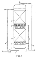
- Figures 1 to 3 give examples of non-limiting embodiment of a mixing and dispensing device according to the invention disposed in a chamber or column upstream of a fixed catalytic bed and operating in liquid flow / gas co-upflow.
- the system according to the present invention allows the distribution and mixing of a gas and liquid flow in a reactor operating in upward flow of fluids.
- the reaction may require the presence and contact of a gas / liquid mixture or a gaseous / liquid / solid mixture in the case of a catalytic reaction. In the latter case, the catalyst can be kept immobile in the reactor or kept boiling by the gas / liquid flow.
- a distribution system 1 can be installed at the inlet of the reactor 2 upstream of a reaction zone and / or between two reaction zones 3.
- the distribution system is fed on the one hand by a line 4 in liquid charge and a line 5 in gaseous charge.
- the liquid flowing in line 4 may be untreated liquid feed or a mixture of untreated liquid feedstock and partially treated product, reinjected after recycle via line 6.
- the feedstock may be composed of a mixture containing pure hydrogen or a mixture containing pure hydrogen as well as residual hydrogen and vaporized hydrocarbons recovered at the top of the reactor and reinjected at the inlet of the reactor via lines 7 and 5. In all cases, the injection of the gas flow is totally separated from the injection of the liquid flow at the level of the distribution system.
- the distribution system 9 When the distribution system 9 is situated between two reaction zones, it is fed on the one hand by the liquid flow coming from the first reaction zone, possibly after separation of the residual gas, as will be explained later, and on the other hand. part by a separate injection into gaseous feed.
- the gaseous feedstock injected via line 8 may be a mixture containing pure hydrogen or a mixture containing pure hydrogen, residual hydrogen and vaporized hydrocarbons recovered at the top of the reactor and reinjected into the reactor at a level which intermediate by lines 7, 5 then 8.
- the figure 2 illustrates an implementation of the present distribution plate (or distributor) at the inlet of a reactor and upstream of a first reaction zone.
- the distributor consists of a flat plate 20 occupying the entire section of the reactor. This plate is connected to vertical tubes 21 which perforate it and thus allow the passage through the distribution plate of the gaseous and liquid fluids.
- the distribution system is thus composed of a series of vertical tubes which cross a plate occupying all the reactor section. These tubes have a lateral passage section which is in the form of one or more orifices 22 which can be of any shape (circular, elliptical or any other shape).
- the number, the arrangement and the size of the orifices 22 for each tube 21 will in particular be chosen according to any technique known to those skilled in the art as a function of the minimum and maximum operating values of the gas flow so that, whatever the range operating in gas flow, the loss of pressure experienced by the gas at the passage of the orifices 22 causes the formation of a gas retention volume 24 under the plate 20 and a liquid / gas interface 18 located below at least one of the orifices 22, or even below the lower level of the orifices 22.
- orifice or lateral passage section it being understood that said sections correspond to the total area passage of the gas generated by all the orifices present on a chimney.
- a circular wall 33 disposed between the plate 20 and the side wall of the reactor and extending beyond the lower end of the hollow tubes 21, can be advantageously
- the wall 33 delimits in this manner the central zone of the reactor where the tubes 21 are located and avoids a possible depressurization of the retention zone 24 because of possible gas leaks.
- the distributor When located at the inlet of the reactor, the distributor is fed separately by the liquid phase and the gas phase respectively by lines 5 and 4 ( figure 1 ).
- the liquid phase is injected at the bottom of the reactor.
- a grid 19 ( figure 2 ) is placed downstream of the point of introduction of the liquid charge, so as to distribute the liquid flows homogeneously over the entire reactor section at the inlet of the distributor.
- any other equivalent means of distribution of the liquid flow may be placed upstream of the dispenser without departing from the scope of the invention.
- the gas phase is injected through the side wall of the reactor using one or more tubes whose gas outlet section is located above the liquid / gas interface 18 and preferably the upper orifice of the reactor. the section of lateral passage of the vertical tubes.
- These tubes may for example be in the form of a bent tube 23, as shown in FIG. figure 2 or in the form of a perforated horizontal tube 26 for distributing the gas flow over a larger section, as shown in FIG. figure 3 .
- the tube 23 will open into the central volume defined by the wall 33 and containing the chimney tubes 21.
- the gas then flows through the orifice or holes 22 located on each vertical tube 21 and mixes within these with rising liquid flow.
- the liquid / gas interface 18 is always located below at least one of the orifices 22 and always above the lowest level tubes.
- this interface 18 is advantageously maintained almost flat and horizontal, which favors a supply of liquid flow and substantially uniform gas flow of all the tubes, avoiding the fluctuations of the interface 18 due to the disengagement of bubbles or pockets of gas .
- Each tube 21 also plays a role of gas / liquid mixer since all the liquid flow mixes with the entire gas flow inside the tubes.
- the sizing of the orifices 22 for each passage section of the liquid and the gas at the level of the tubes makes it possible to control the respective speeds of the two fluids and to optimize the shearing of the gas jets by the liquid in order to increase the gas contact surface. /liquid.
- Internals structured packing type, metal foam ..
- the system presented in this invention allows to perform simultaneously the mixing the gas and liquid flows and distributing them homogeneously over the entire section of the reactor. A homogeneous distribution of the mixture imposes a minimum density of tubes.
- the number of tubes is generally between about 50 and about 1500 tubes / m 2 and preferably between about 100 and about 1000 tubes / m 2 .
- the tube density is generally chosen as a function of the injection density of the gas / liquid mixture.
- the liquid passes through the vertical tubes in the direction of their axis.
- These vertical tubes have one or more openings or orifices 22 on the side wall for the passage of the gas. These lateral openings may preferably be circular or elliptical shaped or rectangular slots.
- the total area of each passage section will generally be calculated so that the pressure loss experienced by the gas causes the formation of a gas retention zone 24 upstream of these orifices.
- the gas / liquid interface 18 is established below at least one of the orifices 22, preventing the passage of liquid through said orifices.
- the diameter of the tubes and the dimensions of the orifices shall be calculated in such a way that for the desired liquid and gas flow rates, the gas / liquid interface is located below the lower level of the lateral passage sections and above the entrance of the vertical tubes.
- the diameter of the vertical tubes is most often calculated to minimize the pressure drop of the liquid during the crossing of the distributor plate. This diameter is generally between about 10 and about 200 mm and preferably between about 20 and about 100 mm.
- the diameter of the orifices or the width of the slots will generally be less than 75% of the diameter of the tubes.
- the height of this gas retention is generally from about 10 to about 1000 mm and preferably from about 50 to about 500 mm.
- the total height 25 of the tubes 21 will often be at least 80 mm or even 100 mm greater than the sum of the height maximum of the gas retention volume and the height between the plate 20 and the upper orifice of the lateral passage sections. This height range generally allows a ratio of at least 3 between the minimum gas flow rate and the maximum gas flow rate to be dispensed. In this way the liquid / gas interface 18 is established above the lower level of the vertical tubes 21 which are therefore fed exclusively by the liquid at the bottom.
- the separate injection of the gas and liquid fluids at the level of the vertical tubes makes it possible to control a homogeneous supply of liquid and gas to the tubes.
- the set of orifices 22 is thus permanently fed solely by the gas and all of the tubes 21 are permanently fed solely by the liquid.
- the gas will pass through the slots or orifices 22 and mix intimately with the liquid, that is to say in the form of fine droplets dispersed homogeneously in the liquid flow.
- the injection speed of the gas will generally be between about 10 cm / s and about 200 m / s and preferably between about 1 m / s and about 100 m / s. The increase in the speed of the gas jet promotes the fragmentation of the bubbles and therefore the gas / liquid contact.
- the dispensing system therefore simultaneously mixes and distribute the gas and liquid flow. Indeed the entire liquid flow is in contact with the entire gas flow before passing through the reaction zone downstream of the distributor plate.
- the figure 3 gives an example of implementation of the distributor plate when it is disposed between two successive reaction zones.
- the distributor consists of a flat plate 20 occupying the entire section of the reactor. This plate is traversed by vertical tubes 21 for the passage of the liquid / gas mixture. The liquid passes through the vertical tubes in the direction of their axis. These vertical tubes have one or more openings or orifices 22 on the side wall for the passage of the gas. These lateral openings may be circular or elliptical shaped or rectangular slots.
- the diameter of the tubes and the passage sections left to the gas are calculated so that, whatever the liquid and gas flow ranges considered in operation, the gas / liquid interface 18 is located below at least one orifices 22 and above the inlet of the vertical tubes 21.
- the characteristics of the tubes are the same as those described in FIG. figure 2 .
- Gas is injected level of the distributor plate through a perforated horizontal tube 26 connected to the pipe 8 ( figure 1 ). This gas may be a cooling gas or a hydrogen supplement for the reaction taking place in the reaction zone located downstream of the distributor.
- the horizontal tube 26 is situated above the liquid / gas interface 18 and advantageously located between the upper level of the upper orifice of the lateral passage sections and the plate 20.
- This tube is pierced by orifices 27 of any shape (for example circular, elliptical, rectangular) which are intended to distribute the secondary gas substantially homogeneously over the entire gas retention volume 24 and thus promote mixing between the primary gas from the first reaction zone and the secondary gas.
- orifices 27 of any shape (for example circular, elliptical, rectangular) which are intended to distribute the secondary gas substantially homogeneously over the entire gas retention volume 24 and thus promote mixing between the primary gas from the first reaction zone and the secondary gas.
- a gas disengagement system is added to prevent the disengagement of the primary gas creates disturbances of the gas / liquid interface 18 . It consists of a substantially flat plate 29 occupying a fraction of the section of the reactor and a perforated annular wall 30 fixed on the periphery of the flat plate 29.
- the wall 30 delimits in the reactor a central volume 31 in which are located all the vertical tubes 21 and a peripheral volume 32 in which there are no tubes 21.
- the plate 29 deflects the gas / liquid flow from the first reaction zone to the peripheral zone 32. In the zone 32 all the gas disengages and joins the gas retention zone 24.
- the liquid passes through the perforated wall 30.
- the size and the number of the orifices of the wall 30 are generally calculated so that the velocity of the liquid through these orifices at least 10 times lower than the rate of rise of the gas bubbles.
- the height of the wall 30 is calculated according to conventional techniques so that for the maximum gas and liquid flow rates of operation, the liquid level is not higher than the upper end of the wall 30. In this way there is no risk of overflow liquid above the wall 30 and therefore no risk of disturbances of the gas / liquid interface 18.
- Example 1 (according to the invention):
- a distribution system according to the invention was tested at the inlet of a 400 mm diameter column in an upward flow of liquid and gas according to the principles described in relation to the figures 1 and 2 .
- the system is placed upstream of a catalytic bed.
- the density of the tubes is 150 tubes / m 2 .
- These tubes have a diameter of 15 mm and a height of 400 mm.
- a single circular orifice 22 of diameter 1 mm is located on each tube at a distance of 10 mm from the plate 20 for the passage of the gas.
- the flow of liquid introduced the bottom of the reactor is 3.5 kg / m 2 .s and the gas flow is 0.018 kg / m 2 .s.
- the injection of the gas at the distributor is carried out using a single tube opening into the gas retention zone thus formed above the orifices 22.
- volume calculations of the retention zone 24 based on the values of the pressure drop of the gas at the orifices and the pressure drop of the liquid during the traversing of the plate, allow to define a distance between the plate 20 and the liquid / gas interface of 303 mm.
- Two sensors of the optical probe type show that the liquid / gas interface is distant under these conditions from the plate 20 with a value of between 250 mm and 330 mm.
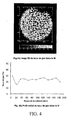
- An image of the gas rate distribution is obtained using a gamma ray tomography system. This image, represented on the figure 4a is acquired 1 m downstream of the entrance of the bed.
- the range (in shades of gray) ranges from black for the zero gas rate, ie virtually no gas in the mixture, to white for a gas rate close to 40% in the gas / liquid mixture .
- the distribution of the gas ratio is very homogeneous over the entire section of the column.
- the figure 4b has a radial profile of the average gas ratio over all the angular positions.
- the device used was the same as that used in the previous example. The only difference concerns the introduction of the gas flow that is injected upstream of the plate in the direction of flow of the fluids, that is to say in mixture with the liquid phase at the lower end of the reactor.
- the operating conditions are the same as that of example 1.
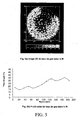
- the figure 5a presents an image of the distribution of the gas ratio obtained in this case over the entire section of the reactor.
- the figure 5b represents the corresponding radial profile of the gas ratio. As can be seen, a significant portion of the bed section (about 50%) is not properly irrigated by the gas flow. In fact, the radial gas rate profile is much less homogeneous than that obtained in the configuration corresponding to the present invention.
Landscapes
- Chemical & Material Sciences (AREA)
- Chemical Kinetics & Catalysis (AREA)
- Organic Chemistry (AREA)
- Engineering & Computer Science (AREA)
- Oil, Petroleum & Natural Gas (AREA)
- Combustion & Propulsion (AREA)
- General Chemical & Material Sciences (AREA)
- Devices And Processes Conducted In The Presence Of Fluids And Solid Particles (AREA)
Claims (12)
- Behälter oder Reaktor (2), umfassend mindestens ein Bett aus Füllkörpern oder gegebenenfalls katalytischen Partikeln (3), Mittel zur Einführung einer flüssigen Phase (4) und Mittel zur Einführung einer gasförmigen Phase (5), Mittel zur Zirkulation in aufsteigender Gleichströmung der flüssigen und gasförmigen Phase und mindestens ein Verteilersystem oder eine Verteilerplatte (1, 9), umfassend:- eine planare Platte (20), die den gesamten Querschnitt des Behälters einnimmt,- Hohlrohre (21), die an ihren jeweiligen Enden offen sind, wobei die Rohre mit der planaren Platte (20) verbunden sind und diese durchdringen, um die Zirkulation der Fluide zwischen der stromaufwärtigen und der stromabwärtigen Seite der Platte zu ermöglichen,- mindestens eine Öffnung (22), die auf der Seitenwand jedes Rohrs (21) und unter der planaren Platte (20) angeordnet ist,wobei die Mittel zur Einführung der flüssigen Phase (4) in dem Behälter (2) stromaufwärts der Verteilerplatte (1, 9) angeordnet sind und die Mittel zur Einführung der gasförmigen Phase (5) in dem Behälter (2) unterhalb der planaren Platte (20) angeordnet sind, in einer Höhe, die im Betrieb die Bildung eines Gasretentionsvolumens (24) unter der Platte (20) und die Bildung einer Austauschfläche zwischen Flüssigkeit und Gas (18) ermöglicht, die unterhalb mindestens einer der Öffnungen (22), die in jedem Rohr (21) vorhanden sind, unterhalb der Mittel zur Einführung der gasförmigen Phase (5) und über dem unteren Ende der Rohre (21) liegt.
- Behälter oder Reaktor nach Anspruch 1, umfassend ein Verteilersystem (1), das stromaufwärts des ersten Katalysatorbetts angebracht ist.
- Behälter oder Reaktor nach Anspruch 2, umfassend ein Mittel zur Verteilung (19) des Flüssigkeitsstroms auf dem Querschnitt des Behälters, das stromaufwärts des Verteilersystems (1) angeordnet ist.
- Behälter oder Reaktor nach einem der vorhergehenden Ansprüche, ferner umfassend ein Verteilersystem (9), das zwischen zwei aufeinander folgenden Katalysatorbetten platziert ist.
- Behälter oder Reaktor nach Anspruch 4, ferner umfassend Mittel zur Trennung des aus dem ersten Bett stammenden Restgases, die stromaufwärts des Verteilersystems (9) angeordnet sind.
- Behälter oder Reaktor nach Anspruch 5, wobei die Mittel zur Trennung eine Platte (29), die einen Teil des Querschnitts des Behälters einnimmt, und eine ringförmige durchdrungene Wand (30), die am Rand der Platte (29) befestigt ist, wobei die Wand (30) in dem Behälter ein zentrales Volumen (31) begrenzt, in dem sich die Rohre (21) befinden, und ein peripheres Volumen (32), das frei von Rohren (21) ist, umfassen.
- Behälter oder Reaktor nach einem der vorhergehenden Ansprüche, wobei die Mittel zur Einführung der gasförmigen Phase mindestens ein gekrümmtes Rohr (23) und/oder mindestens ein horizontal durchdrungenes Rohr (26) umfassen.
- Behälter oder Reaktor nach einem der vorhergehenden Ansprüche, wobei die Dichte der Rohre in einer Verteilerplatte im Bereich zwischen etwa 50 Rohren/m2 und etwa 1.500 Rohren/m2 liegt.
- Behälter oder Reaktor nach einem der vorhergehenden Ansprüche, wobei der Durchmesser der Rohre (21) im Bereich zwischen etwa 10 mm und etwa 200 mm liegt.
- Verfahren zum Mischen und zum Verteilen einer flüssigen Phase und einer gasförmigen Phase innerhalb eines Behälters oder eines Reaktors nach einem der Ansprüche 1 bis 9, wobei die folgenden Schritte durchgeführt werden:a) Einführen der flüssigen Phase in einen Behälter stromaufwärts einer Verteilerplatte, umfassend eine planare Platte, die den gesamten transversalen Querschnitt des Behälters einnimmt, Rohre, die hohl und an ihren jeweiligen Enden offen sind, wobei die Rohre mit der planaren Platte verbunden sind und diese durchdringen, um die Zirkulation der Fluide zwischen der stromaufwärtigen und der stromabwärtigen Seite der Platte zu ermöglichen, und mindestens eine Öffnung, die an jedem Rohr angeordnet ist,b) Einführen der gasförmigen Phase in den Behälter in Höhe der Verteilerplatte,c) Einstellen des Gas- und/oder Flüssigkeitsdurchflusses, um unter der Platte ein Gasretentionsvolumen, das durch den Druckverlust gebildet wird, den das Gas während seiner Passage durch die Öffnungen erfährt, in die die gasförmige Phase eingeführt wird und eine Austauschfläche zwischen Flüssigkeit und Gas, die unterhalb mindestens einer der Öffnungen und oberhalb des unteren Endes der Rohre liegt, herzustellen,d) Einführen des aus Schritt c) stammenden Gas/Flüssigkeitsgemischs in ein Bett aus gegebenenfalls katalytischen Partikeln oder ein Füllkörperbett.
- Verfahren nach Anspruch 10, wobei der Durchfluss der gasförmigen Phase im Bereich zwischen 5.10-4 kg/m2.s und 10 kg/m2.s liegt und wobei der Durchfluss der flüssigen Phase im Bereich zwischen 0 und 100 kg/m2.s liegt.
- Verfahren zur Herstellung eines Behälters nach einem der Ansprüche 1 bis 9, wobei die Anzahl der Öffnungen, die auf den Rohren vorhanden sind und/oder die Anordnung der Öffnungen, die auf den Rohren vorhanden sind und/oder die Größe der Öffnungen, die auf den Rohren vorhanden sind und/oder der Durchmesser der Rohre und/oder die Länge der Rohre in Abhängigkeit von den Minimal- und Maximalwerten des Durchflusses der gasförmigen Phase und der flüssigen Phase während des Betriebs des Behälters angepasst wird, um die Bildung eines Gasretentionsvolumens zu erhalten, das durch den Druckverlust, den das Gas während seiner Passage durch die Öffnungen erfährt, gebildet wird.
Applications Claiming Priority (1)
| Application Number | Priority Date | Filing Date | Title |
|---|---|---|---|
| PCT/FR2003/002158 WO2005014161A1 (fr) | 2003-07-10 | 2003-07-10 | Plateau de distribution d’une phase gazeuse et d'une phase liquide |
Publications (2)
| Publication Number | Publication Date |
|---|---|
| EP1646444A1 EP1646444A1 (de) | 2006-04-19 |
| EP1646444B1 true EP1646444B1 (de) | 2013-09-11 |
Family
ID=34130579
Family Applications (1)
| Application Number | Title | Priority Date | Filing Date |
|---|---|---|---|
| EP03817962.8A Expired - Lifetime EP1646444B1 (de) | 2003-07-10 | 2003-07-10 | Ventilplatte zum verteilen einer gasförmigen phase und einer flüssigen phase |
Country Status (5)
| Country | Link |
|---|---|
| EP (1) | EP1646444B1 (de) |
| JP (1) | JP4834879B2 (de) |
| KR (1) | KR100979987B1 (de) |
| AU (1) | AU2003263281A1 (de) |
| WO (1) | WO2005014161A1 (de) |
Families Citing this family (2)
| Publication number | Priority date | Publication date | Assignee | Title |
|---|---|---|---|---|
| DE102004021128A1 (de) * | 2004-04-29 | 2005-11-24 | Oxeno Olefinchemie Gmbh | Vorrichtung und Verfahren für die kontinuierliche Umsetzung einer Flüssigkeit mit einem Gas an einem festen Katalysator |
| DE102005050283A1 (de) * | 2005-10-20 | 2007-04-26 | Basf Ag | Verteilervorrichtung für ein Gas-Flüssigphasengemisch für Apparate |
Family Cites Families (4)
| Publication number | Priority date | Publication date | Assignee | Title |
|---|---|---|---|---|
| JPS61287438A (ja) * | 1985-06-14 | 1986-12-17 | Mitsubishi Heavy Ind Ltd | 三相流動反応器の分散装置 |
| JPS63291638A (ja) | 1987-05-22 | 1988-11-29 | Mitsubishi Heavy Ind Ltd | 三相流動反応装置における気液分散器 |
| US4966101A (en) * | 1988-05-17 | 1990-10-30 | Ube Industries, Ltd. | Fluidized bed apparatus |
| US6554994B1 (en) * | 1999-04-13 | 2003-04-29 | Chevron U.S.A. Inc. | Upflow reactor system with layered catalyst bed for hydrotreating heavy feedstocks |
-
2003
- 2003-07-10 WO PCT/FR2003/002158 patent/WO2005014161A1/fr not_active Ceased
- 2003-07-10 EP EP03817962.8A patent/EP1646444B1/de not_active Expired - Lifetime
- 2003-07-10 JP JP2005507543A patent/JP4834879B2/ja not_active Expired - Lifetime
- 2003-07-10 KR KR1020067000565A patent/KR100979987B1/ko not_active Expired - Lifetime
- 2003-07-10 AU AU2003263281A patent/AU2003263281A1/en not_active Abandoned
Also Published As
| Publication number | Publication date |
|---|---|
| EP1646444A1 (de) | 2006-04-19 |
| AU2003263281A1 (en) | 2005-02-25 |
| KR20060038990A (ko) | 2006-05-04 |
| KR100979987B1 (ko) | 2010-09-03 |
| JP2007514514A (ja) | 2007-06-07 |
| WO2005014161A1 (fr) | 2005-02-17 |
| JP4834879B2 (ja) | 2011-12-14 |
Similar Documents
| Publication | Publication Date | Title |
|---|---|---|
| EP1147809B1 (de) | Vorrichtung, die einen Wasserstrahlregler enthält, zur Verteilung einer mehrphasigen Mischung über ein Festbett | |
| EP2138216B1 (de) | Vorrichtung mit einem Prallblech zur Verteilung eines Fluides in einer mehrstufigen Kolonne | |
| EP1446221B1 (de) | Vorrichtung zum verteilen einer mehrphasenmischung in einem granulat-festbett durch einen strahlverteiler mit aufkantung | |
| EP1866068B1 (de) | Vorrichtung zum mischen und verteilen eines gases und einer flüssigkeit vor einer granulatschüttung | |
| EP2138215B1 (de) | Vorrichtung zur Verteilung eines Fluides in einer mehrstufigen Kolonne und zur Vergleichmässigung der Verweilzeiten auf jeder Stufe | |
| EP1382376B1 (de) | Vorrichtung zum Mischen und Verteilen eines dichten Fluids und eines leichten Fluids oberhalb eines Partikelbetts für einen abwärtsströmenden Auslauf | |
| EP2647425B1 (de) | Katalytischer reaktor mit einer härtungsvorrichtung, die mit einer tangentialen einspritzung einer härtungsflüssigkeit ausgestattet ist | |
| EP1180393A2 (de) | Vorrichtung zur Einspritzung von Fluid zwischen zwei Schichten zur gleichzeitigen Ausführung und Verteilung einer Mehrphasenmischung | |
| EP1180394B1 (de) | Vorrichtung zur Einspritzung von Fluid zwischen zwei Schichten zur gleichzeitigen Ausführung und Verteilung einer Mehrphasenmischung | |
| EP2162207B1 (de) | Gehäuse mit einer granularen schicht und mit verteilung einer gasphase und einer flüssigphase, die entsprechend einem ansteigenden fluss in besagtem gehäuse fliessen | |
| EP1464383A1 (de) | Vorrichtung zur Mischung und Verteilung einer Gasphase und einer Flüssigkeitphase zur Zufuhr in ein Festbett | |
| EP3618947B1 (de) | Neue vorrichtung zum verteilen eines polyphasengemisches in einer kammer mit einem fluidisierten medium | |
| EP3538627B1 (de) | Neue vorrichtung zur gas-flüssig-trennung für dreiphasige wirbelschichtreaktoren wie solche zur verwendung im h-öl-prozess | |
| WO2009133254A1 (fr) | Systeme de distribution et de collecte des fluides dans une colonne multi etagee | |
| EP1646444A1 (de) | Ventilplatte zum verteilen einer gasförmigen phase und einer flüssigen phase | |
| CA3020940A1 (fr) | Panier amovible pour reacteur catalytique | |
| FR3043339A1 (fr) | Dispositif de filtration et de distribution pour reacteur catalytique | |
| FR2553300A1 (fr) | Procede pour uniformiser un courant ascendant de gaz et de liquide dans un reacteur a lit fluidise et grille etagee de distribution d'ecoulement pour sa mise en oeuvre | |
| EP0778332B1 (de) | Verfahren und Einrichtung zur Visbreaking von schweren Kohlenwasserstoffeinsätzen | |
| FR2826876A1 (fr) | Dispositif interne de separation d'un melange comprenant au moins une phase gazeuse et une phase liquide | |
| FR2980719A1 (fr) | Plateau distributeur pour la distribution d'un melange polyphasique avec cheminees tronquees en peripherie. | |
| EP3536398B1 (de) | Vorrichtung zur mischung eines fluides für einen katalytischen bett | |
| FR3066410B1 (fr) | Dispositif de melange et de distribution avec zone de retournement | |
| FR2987280A1 (fr) | Reacteur catalytique avec systeme de distribution a caissons | |
| WO2019072601A1 (fr) | Dispositif de melange et de distribution avec ouverture longitudinale |
Legal Events
| Date | Code | Title | Description |
|---|---|---|---|
| PUAI | Public reference made under article 153(3) epc to a published international application that has entered the european phase |
Free format text: ORIGINAL CODE: 0009012 |
|
| 17P | Request for examination filed |
Effective date: 20060210 |
|
| AK | Designated contracting states |
Kind code of ref document: A1 Designated state(s): BE DE FR GB NL |
|
| DAX | Request for extension of the european patent (deleted) | ||
| RBV | Designated contracting states (corrected) |
Designated state(s): BE DE FR GB NL |
|
| 17Q | First examination report despatched |
Effective date: 20071127 |
|
| GRAP | Despatch of communication of intention to grant a patent |
Free format text: ORIGINAL CODE: EPIDOSNIGR1 |
|
| INTG | Intention to grant announced |
Effective date: 20130402 |
|
| GRAS | Grant fee paid |
Free format text: ORIGINAL CODE: EPIDOSNIGR3 |
|
| GRAA | (expected) grant |
Free format text: ORIGINAL CODE: 0009210 |
|
| AK | Designated contracting states |
Kind code of ref document: B1 Designated state(s): BE DE FR GB NL |
|
| REG | Reference to a national code |
Ref country code: GB Ref legal event code: FG4D Free format text: NOT ENGLISH |
|
| REG | Reference to a national code |
Ref country code: DE Ref legal event code: R081 Ref document number: 60344922 Country of ref document: DE Owner name: INSTITUT FRANCAIS DU PETROLE, FR Free format text: FORMER OWNER: INSTITUT FRANCAIS DU PETROLE, RUEIL-MALMAISON, HAUTS-DE-SEINE, FR |
|
| REG | Reference to a national code |
Ref country code: DE Ref legal event code: R096 Ref document number: 60344922 Country of ref document: DE Effective date: 20131107 |
|
| REG | Reference to a national code |
Ref country code: NL Ref legal event code: T3 |
|
| REG | Reference to a national code |
Ref country code: DE Ref legal event code: R097 Ref document number: 60344922 Country of ref document: DE |
|
| PLBE | No opposition filed within time limit |
Free format text: ORIGINAL CODE: 0009261 |
|
| STAA | Information on the status of an ep patent application or granted ep patent |
Free format text: STATUS: NO OPPOSITION FILED WITHIN TIME LIMIT |
|
| 26N | No opposition filed |
Effective date: 20140612 |
|
| REG | Reference to a national code |
Ref country code: DE Ref legal event code: R097 Ref document number: 60344922 Country of ref document: DE Effective date: 20140612 |
|
| REG | Reference to a national code |
Ref country code: FR Ref legal event code: PLFP Year of fee payment: 14 |
|
| REG | Reference to a national code |
Ref country code: FR Ref legal event code: PLFP Year of fee payment: 15 |
|
| REG | Reference to a national code |
Ref country code: FR Ref legal event code: PLFP Year of fee payment: 16 |
|
| PGFP | Annual fee paid to national office [announced via postgrant information from national office to epo] |
Ref country code: NL Payment date: 20220726 Year of fee payment: 20 |
|
| PGFP | Annual fee paid to national office [announced via postgrant information from national office to epo] |
Ref country code: GB Payment date: 20220719 Year of fee payment: 20 Ref country code: DE Payment date: 20220727 Year of fee payment: 20 |
|
| PGFP | Annual fee paid to national office [announced via postgrant information from national office to epo] |
Ref country code: FR Payment date: 20220727 Year of fee payment: 20 Ref country code: BE Payment date: 20220726 Year of fee payment: 20 |
|
| REG | Reference to a national code |
Ref country code: DE Ref legal event code: R071 Ref document number: 60344922 Country of ref document: DE |
|
| REG | Reference to a national code |
Ref country code: NL Ref legal event code: MK Effective date: 20230709 |
|
| REG | Reference to a national code |
Ref country code: BE Ref legal event code: MK Effective date: 20230710 |
|
| REG | Reference to a national code |
Ref country code: GB Ref legal event code: PE20 Expiry date: 20230709 |
|
| PG25 | Lapsed in a contracting state [announced via postgrant information from national office to epo] |
Ref country code: GB Free format text: LAPSE BECAUSE OF EXPIRATION OF PROTECTION Effective date: 20230709 |