EP1646746B1 - Wasserdurchlüssige trommel für die hydrodynamische vernadelung textilen warenbahnen und verfahren zur herstellung der trommel - Google Patents
Wasserdurchlüssige trommel für die hydrodynamische vernadelung textilen warenbahnen und verfahren zur herstellung der trommel Download PDFInfo
- Publication number
- EP1646746B1 EP1646746B1 EP04732620A EP04732620A EP1646746B1 EP 1646746 B1 EP1646746 B1 EP 1646746B1 EP 04732620 A EP04732620 A EP 04732620A EP 04732620 A EP04732620 A EP 04732620A EP 1646746 B1 EP1646746 B1 EP 1646746B1
- Authority
- EP
- European Patent Office
- Prior art keywords
- drum
- sieve
- coating
- woven
- knitted
- Prior art date
- Legal status (The legal status is an assumption and is not a legal conclusion. Google has not performed a legal analysis and makes no representation as to the accuracy of the status listed.)
- Expired - Lifetime
Links
- 239000004753 textile Substances 0.000 title claims abstract description 14
- 238000004519 manufacturing process Methods 0.000 title claims description 11
- 238000000034 method Methods 0.000 title claims description 8
- 239000000463 material Substances 0.000 title abstract description 11
- 239000011248 coating agent Substances 0.000 claims abstract description 42
- 238000000576 coating method Methods 0.000 claims abstract description 41
- PXHVJJICTQNCMI-UHFFFAOYSA-N Nickel Chemical compound [Ni] PXHVJJICTQNCMI-UHFFFAOYSA-N 0.000 claims description 12
- 239000002184 metal Substances 0.000 claims description 8
- 229910052751 metal Inorganic materials 0.000 claims description 8
- 229910052759 nickel Inorganic materials 0.000 claims description 6
- 238000000926 separation method Methods 0.000 claims 2
- HCHKCACWOHOZIP-UHFFFAOYSA-N Zinc Chemical compound [Zn] HCHKCACWOHOZIP-UHFFFAOYSA-N 0.000 claims 1
- 238000007598 dipping method Methods 0.000 claims 1
- 238000009713 electroplating Methods 0.000 claims 1
- 239000004745 nonwoven fabric Substances 0.000 claims 1
- 238000005728 strengthening Methods 0.000 claims 1
- 229910052725 zinc Inorganic materials 0.000 claims 1
- 239000011701 zinc Substances 0.000 claims 1
- 239000004744 fabric Substances 0.000 abstract description 48
- XLYOFNOQVPJJNP-UHFFFAOYSA-N water Substances O XLYOFNOQVPJJNP-UHFFFAOYSA-N 0.000 description 5
- 230000037303 wrinkles Effects 0.000 description 4
- 238000010276 construction Methods 0.000 description 3
- 230000002093 peripheral effect Effects 0.000 description 3
- 238000005246 galvanizing Methods 0.000 description 2
- 238000007747 plating Methods 0.000 description 2
- 238000012216 screening Methods 0.000 description 2
- 150000001875 compounds Chemical class 0.000 description 1
- 230000003750 conditioning effect Effects 0.000 description 1
- 238000001035 drying Methods 0.000 description 1
- 230000000694 effects Effects 0.000 description 1
- 238000005476 soldering Methods 0.000 description 1
- 239000007787 solid Substances 0.000 description 1
- 238000007711 solidification Methods 0.000 description 1
- 230000008023 solidification Effects 0.000 description 1
- 230000000087 stabilizing effect Effects 0.000 description 1
- 238000003466 welding Methods 0.000 description 1
Images


Classifications
-
- D—TEXTILES; PAPER
- D04—BRAIDING; LACE-MAKING; KNITTING; TRIMMINGS; NON-WOVEN FABRICS
- D04H—MAKING TEXTILE FABRICS, e.g. FROM FIBRES OR FILAMENTARY MATERIAL; FABRICS MADE BY SUCH PROCESSES OR APPARATUS, e.g. FELTS, NON-WOVEN FABRICS; COTTON-WOOL; WADDING ; NON-WOVEN FABRICS FROM STAPLE FIBRES, FILAMENTS OR YARNS, BONDED WITH AT LEAST ONE WEB-LIKE MATERIAL DURING THEIR CONSOLIDATION
- D04H18/00—Needling machines
- D04H18/04—Needling machines with water jets
-
- C—CHEMISTRY; METALLURGY
- C25—ELECTROLYTIC OR ELECTROPHORETIC PROCESSES; APPARATUS THEREFOR
- C25D—PROCESSES FOR THE ELECTROLYTIC OR ELECTROPHORETIC PRODUCTION OF COATINGS; ELECTROFORMING; APPARATUS THEREFOR
- C25D7/00—Electroplating characterised by the article coated
- C25D7/04—Tubes; Rings; Hollow bodies
Definitions
- the invention relates to a water-permeable drum for the hydrodynamic needling of textile webs such as nonwoven, tissue, fabric, knitted fabric od.
- textile webs such as nonwoven, tissue, fabric, knitted fabric od.
- Such drums are known in the field of continuous drying by GBM 1 886 883.
- the construction is advantageous because the textile material to be treated does not rest on the perforated drum, which would result in an uneven flow through the fabric web, a sign of the perforation of the drum on the textile material.
- a coarse screen fabric preferably rests on the drum first, and then a finer one, on which the textile material then comes to rest, then the treatment medium can treat the textile material uniformly over the surface.
- the beam arranged by closely spaced strips, including on the EP-A-0 841 424 is referenced.
- Another possibility reveals the US-A-5 609 046 according to which the mesh is replaced by welded on the screen drum like welded webs, but this leads to great problems in the assembly.
- the invention consists in that the mesh fabric or knitted fabric has a coating which stabilizes the crossing points of the wires.
- the screen cover consists of interwoven or verwunken metal wires. Of necessity there is always the possibility of a movement of the metal wires at the crossing points of this coating. This is prevented by the coating. Thus, no more wrinkles over the surface of the drum can arise.
- the mesh fabric or knitted fabric produced as a hose with diagonal wire structure then pulled over the screen drum and under longitudinal stress at full-surface contact on the basket drum shell or better on the previously applied beam, such as coarse mesh fabric to plant is brought.
- the coating on the two end faces to be connected to the drum, which is usually done by soldering.
- the coating is to be coated, with a coating which stabilizes the mesh or knitted fabric at the intersection points of the wires.
- the coating In a simpler manufacturing process, it is also possible to perform the coating before mounting the coating. It is essential in the desired drum only that the coating rests as firmly as possible on the screen drum over the entire surface and in addition the mobility of the wires is repealed. This is produced by the proposed coating, which can be effected by plastic, or by a galvanically generated metal coating, for example by nickel plating.
- EP-A-0 841 424 is in Fig. 1 describes a device in which the textile material to be acted upon by the water jets is guided between two conically running towards each other Endloss screens and thus the water jets first penetrate through a sieve to effect the needling.
- the textile material lies directly on the drum as it is in the EP-A-1 001 064 in the Fig. 2 is shown, and the one or more nozzle bars are associated with the exiting water jets directly to the fabric.
- the water-permeable drum according to the construction of the invention applies.
- the perforated screening drum 1 (the holes 2 are in Fig. 2 represented) serves with its peripheral surface as the fabric carrying and forward transporting element.
- the holes in the peripheral surface are used for radially directed removal of the water of the impinging jets of water, including the interior of the drum is set under induced draft. So that the uniformly over the surface of the textile takes place, is in accordance Fig. 1 and 2 pulled over the drum 1 a screen mesh 3, the fabric can also be finer structure, and soldered under tension 4 at the end faces with the drum 1.
- the mesh fabric or knitted fabric consists of a tube with a diagonal wire structure, so that the tube is reduced in diameter during the longitudinal tension generated for assembly and thus comes to rest on the drum 1 over its entire surface.
- the completely assembled drum 1 + 3 becomes Fig. 2 immersed in a bath 5 and coated there by the galvanic method with nickel.
- the coating can also be done differently z. B. by galvanizing or with a plastic material that can be sprayed on.
- FIGS. 3 and 4 reveal the same thing, only on the coarse screen fabric 3 is still drawn in the structure finer, tubular screen mesh 6 and also brought under tension 4 fixed on the drum 1 + 3 for conditioning and soldered to the drum at the front pages. Only then does the coating take place according to Figure 4 ,
- a screen drum with looping sieve fabric or knitted fabric which is stabilized by a coating at the crossing points of the wires can be generated in a variety of ways.
- a tube 6 'made of a desired woven or knitted fabric according to a) suitably, then dipped and coated according to b) in a galvanizing 5 and then pushed over an associated drum 1' and the end face with the drum clamped 4 "soldered, stuck or the like attached (not shown).
- Fig. 7 There is according to Fig. 7a pushed the tubular screen fabric 6 "with diagonal structure on the screen drum 1, detected by means of the auxiliary construction on the front sides, stretched and soldered under tension 4" od at the ends with the drum 1 od. Like. Attached. This corresponds to the illustration in Fig. 1 or 3 , The final mounted drum 1 with fully lying and soldered screen fabric 6 "is then according to Fig. 7b placed in the dip for coating to the desired drum with also through the coating according to Fig. 9 to obtain a firmly seated and coated sieve fabric 6 ".
- the stabilizing coating of the screen fabric or knitted fabric goes out of the 8 and 9 out.
- a connection 10 of the superimposed wires 9 is achieved in any case at all crossing points of the wires 9, which resembles a welding of the wires 9.
- Fig. 8 corresponds to the manufacturing process of the drum according to the Fig. 5 and 6
- Fig. 9 Not only is the wire mesh stabilized but it is also bonded to the backing by the coating 10 '.
- the pad can the screen drum 1 according to Fig. 1 or the beam 3 according to Fig. 3 be, in turn, also with the screen drum 1 after the manufacturing process Fig. 7 through the coating 10 'is connected.
Landscapes
- Chemical & Material Sciences (AREA)
- Engineering & Computer Science (AREA)
- Chemical Kinetics & Catalysis (AREA)
- Electrochemistry (AREA)
- Materials Engineering (AREA)
- Metallurgy (AREA)
- Organic Chemistry (AREA)
- Textile Engineering (AREA)
- Treatment Of Fiber Materials (AREA)
- Nonwoven Fabrics (AREA)
- Preliminary Treatment Of Fibers (AREA)
Description
- Die Erfindung bezieht sich auf eine wasserdurchlässige Trommel für die hydrodynamische Vernadelung von textilen Warenbahnen wie Nonwoven, Tissue, Gewebe, Gewirke od. dgl. zu deren Verfestigung und/oder Oberflächenveredelung wie auch Strukturierung, bestehend aus einer mit Öffnungen versehenen, in sich stabilen Trommel, über deren Außenumfang zumindest ein schlauchförmiges Siebgewebe oder -gewirke aus Metalldrähten gezogen und an der Trommel stirnseitig befestigt ist.
- Derartige Trommeln sind auf dem Gebiet des durchströmenden Trocknens durch das GBM 1 886 883 bekannt. Die Konstruktion ist vorteilhaft, weil das zu behandelnde Textilgut nicht auf der gelochten Trommel aufliegt, was eine ungleichmäßige Durchströmung der Warenbahn, eine Abzeichnung der Lochung der Trommel auf dem Textilgut zur Folge hätte. Liegt dagegen auf der Trommel vorzugsweise zunächst ein grobes Siebgewebe auf und dann ein feineres, auf dem dann das Textilgut zu liegen kommt, so kann das Behandlungsmedium das Textilgut über die Fläche gleichbleibend behandeln. Für die hydrodynamische Vernadelung ist auch überlegt worden, das grobe Siebgewebe, also den Unterzug, durch dicht beieinander angeordnete Streifen zu ersetzen, wozu auf die
EP-A-0 841 424 verwiesen wird. Eine andere Möglichkeit offenbart dieUS-A-5 609 046 , nach der das Siebgewebe durch auf die Siebtrommel befestigte wie geschweißte Stege ersetzt wird, was aber in der Montage zu großen Problemen führt. - Die Praxis hat ergeben, dass sich über die Fläche des Siebgewebes oder -gewirkes Falten bilden. Falten im Siebgewebe entstehen sogar dann, wenn das Siebgewebe aus einem diagonal gewebten oder genutzten schlauchförmigen Gewebe besteht, das sich bei einer bei der Montage erzeugten axialen Spannung im Durchmesser verkleinert und somit während der Monatage fest und vollflächig auf der tragenden Siebtrommel oder auf dem Unterzug zur Auflage kommt. Nachteilig sind insbesondere Falten, die in der Praxis, also bei der Nutzung der Vernadelungstrommel als das Textilgut transpor-Der Erfindung liegt die Aufgabe zugrunde, eine Trommel mit diese umschlingendem Siebgewebe oder -gewirke zu entwickeln, bei der diese Faltenbildung unmöglich gemacht ist.
- Ausgehend von der Trommel anfangs genannter Art besteht die Erfindung darin, dass das Siebgewebe oder -gewirke eine die Kreuzungspunkte der Drähte stabilisierende Beschichtung aufweist. Der Siebüberzug besteht aus miteinander verwebten oder verwirkten Metalldrähten. Notgedrungen besteht stets die Möglichkeit einer Bewegung der Metalldrähte an den Kreuzungspunkten dieses Überzuges. Durch die Beschichtung ist das verhindert. Damit können auch keine Falten mehr über die Fläche der Trommel entstehen.
- Es ist besonders vorteilhaft, wenn - wie bekannt - das Siebgewebe oder -gewirke als Schlauch mit diagonaler Drahtstruktur hergestellt, dann über die Siebtrommel gezogen und unter Längsspannung bei vollflächiger Auflage auf dem Siebtrommelmantel oder besser auf dem vorher aufgebrachten Unterzug, wie gröberem Siebgewebe, zur Anlage gebracht wird. In diesem gespannten Zustand ist der Überzug an den beiden Stirnseiten mit der Trommel zu verbinden, was üblicherweise durch Löten erfolgt. Anschließend ist der Überzug zu beschichten, und zwar mit einer das Siebgewebe oder - gewirke an den Kreuzungspunkte der Drähte stabilisierenden Beschichtung.
- In einem einfacheren Herstellungsvorgang ist es auch möglich, die Beschichtung vor der Montage des Überzuges durchzuführen. Wesentlich ist bei der gewünschten Trommel nur, dass der Überzug möglichst fest auf der Siebtrommel vollflächig aufliegt und zusätzlich die Beweglichkeit der Drähte aufgehoben ist. Dies wird durch die vorgeschlagene Beschichtung erzeugt, was durch Kunststoff bewirkt werden kann, oder durch eine galvanische erzeugte metallne Beschichtung, zum Beispiel durch Vernickeln.
- Eine Trommel der erfindungsgemäßen Art und der mögliche Werdevorgang der letztendlich beschichteten Trommel mit Überzug ist in der Zeichnung beispielhaft dargestellt. Es zeigen:
- Fig. 1
- In perspektivischer Darstellung eine gelochte Siebtrommel mit einem unter Spannung aufgezogenen Siebgewebe, die gemäß
- Fig. 2
- insgesamt in ein Bad getaucht wird zur Erzeugung eines galvanisch erzeugten Überzuges sowohl über das fertig montierte Siebgewebe und auch über die Trommel, Gleiches offenbart die
- Fig. 3
- bei einer gelochte Trommel mit vorher auf die Trommel aufgezogenem groben Siebgewebe als Unterzug für das zusätzliche feinere Siebgewebe. Auch diese montierte Trommel wird gemäß
- Fig. 4
- insgesamt in das Bad getaucht zur galvanischen Beschichtung mit Nickel.
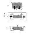
- Fig. 5
- zeigt den Herstellungsvorgang einer Siebtrommel mit überzogenem Siebgewebe mit den Teilschritten a) - c), wobei der Siebgewebeschlauch ohne Axialspannung z. B. vernickelt und dann über die Trommel gezogen und mit der Trommel verlötet, verklemmt oder dgl. angeheftet wird; dann die
- Fig. 6
- sie zeigt den Herstellungsvorgang einer Siebtrommel mit überzogenem Siebgewebe mit den Teilschritten a) - c), wobei der Siebgewebeschlauch mit Axialspannung, aber vor der Montage mit der Siebtrommel z. B. vernickelt und dann über die Trommel gezogen und mit der Trommel unter Axialspannung verlötet, verklemmt oder dgl. angeheftet wird, und dann die
- Fig. 7
- sie zeigt den Herstellungsvorgang einer Siebtrommel mit überzogenem Siebgewebe mit den Teilschritten a) - b), wobei der zunächst unbehandelte Siebgewebeschlauch mit Diagonalstruktur über die Siebtrommel gezogen, dann unter Längsspannung gesetzt und mit der Siebtrommel an den Stirnseiten verlötet, verklemmt oder dgl. angeheftet wird. Erst dann wird die montierte Trommel in das Bad getaucht zur Vernickelung aller Teile. Die
- Fig.B
- 8 zeigt weiterhin in vergrößerter Darstellung einen Querschnitt durch das beschichtete Siebgewebe oder -gewirke und
- Fig. 9 in
- ähnlicher Darstellung wie
Fig. 8 das beschichtete Siebgewebe, das aber montiert auf der Siebtrommel beschichtet wurde, so dass durch die Beschichtung auch eine Verbindung des Siebgewebes mit der Umfangsfläche der Siebtrommel existiert. - In der oben erwähnten
EP-A-0 841 424 ist inFig. 1 eine Vorrichtung beschrieben, bei der das mit den Wasserstrahlen zu beaufschlagende Textilgut zwischen zwei konisch aufeinander zu vorlaufenden Endlossieben geführt ist und damit die Wasserstrahlen zunächst durch das eine Sieb dringen, um die Vernadelung zu bewirken. Normalerweise liegt das Textilgut direkt auf der Trommel auf wie es in derEP-A-1 001 064 in derFig. 2 dargestellt ist, und der oder die Düsenbalken sind mit den austretenden Wasserstrahlen dem Textilgut direkt zugeordnet. Für beide Anwendungsfälle gilt die wasserdurchlässige Trommel nach der Konstruktion nach der Erfindung. - Die gelochte Siebtrommel 1 (die Löcher 2 sind in
Fig. 2 dargestellt) dient mit ihrer Umfangsfläche als das das Textilgut tragende und vorwärts transportierende Element. Die Löcher in der Umfangsfläche dienen zum radial gerichteten Abtransport des Wassers der auftreffenden Wasserstrahlen, wozu der Innenraum der Trommel unter Saugzug gesetzt ist. Damit das gleichmäßig über die Fläche des Textilgutes erfolgt, ist gemäßFig. 1 und 2 über die Trommel 1 ein Siebgewebe 3 gezogen, das Gewebe kann auch feinerer Struktur sein, und unter Spannung 4 an den Stirnseiten mit der Trommel 1 verlötet. Üblicherweise besteht das Siebgewebe oder -gewirke aus einem Schlauch mit diagonaler Drahtstruktur, so dass der Schlauch bei der zur Montage erzeugten Längsspannung sich im Durchmesser verkleinert und damit vollflächig auf der Trommel 1 zur Auflage kommt. - Da die Drahtstruktur des Siebgewebes, oder -gewirkes 3 auch bei unter Spannung befindlichem Schlauch beweglich bleibt, wird die fertig montierte Trommel 1 + 3 gemäß
Fig. 2 in ein Bad 5 getaucht und dort nach der galvanischen Methode mit Nickel beschichtet. Die Beschichtung kann auch anders erfolgen z. B. durch Verzinken oder mit einem Kunststoffmaterial, das auch aufgespritzt werden kann. Dadurch wird nicht nur die Drahtstruktur des Siebgewebes 3 bleibend fixiert, sondern auch vollflächig eine Verbindung des Siebgewebes 3 mit der Trommel 1 erzeugt. - Die
Figuren 3 und 4 offenbaren das Gleiche, nur ist auf das gröbere Siebgewebe 3 noch ein in der Struktur feineres, schlauchförmiges Siebgewebe 6 gezogen und ebenfalls unter Spannung 4 fest auf der Trommel 1 + 3 zur Anlage gebracht und mit der Trommel an den Stirnseiten verlötet. Erst anschließend erfolgt die Beschichtung gemäßFig.4 . - Die Herstellung einer Siebtrommel mit sie umschlingendem Siebgewebe oder -gewirke, das durch eine Beschichtung an den Kreuzungspunkten der Drähte stabilisiert ist, kann durch vielfältige Weise erzeugt werden. Gemäß
Fig. 5 wird in einfacher Weise ein Schlauch 6' aus einem gewünschten Gewebe oder Gewirke gemäß a) passend hergestellt, dann gemäß b) in ein Galvanisierungsbad 5 getaucht und beschichtet und dann über eine zugehörige Trommel 1' geschoben und stirnseitig mit der Trommel gespannt 4" verlötet, verklemmt oder dgl. angeheftet (nicht dargestellt). - Besser ist es, wenn - wie in
Fig. 6 dargestellt - das schlauchförmige Siebgewebe 6' mit einer Hilfskonstruktion 7, 8 seitlich erfasst und gemäß der Pfeile 4' in die richtige Dimension gestreckt wird. Anschließend wird wie beiFig. 5b das Siebgewebe 6', wieder ohne Trommel, aber im gespannten Zustand, im Bad 5 beschichtet und dann gemäß c) über die Siebtrommel 1' geschoben und an den Stirnseiten mit der Trommel unter Spannung 4° verlötet, verklemmt oder dgl. angeheftet (nicht dargestellt). - Die beste Lösung offenbart die
Fig. 7 . Dort wird gemäßFig. 7a das schlauchförmige Siebgewebe 6" mit Diagonalstruktur über die Siebtrommel 1 geschoben, mittels der Hilfskonstruktion an den Stirnseiten erfasst, gestreckt und unter Spannung 4" an den Stirnseiten mit der Trommel 1 verlötet od. dgl. befestigt. Dies entspricht der Darstellung inFig. 1 oder 3 . Die endgültig montierte Trommel 1 mit vollflächig aufliegendem und verlöteten Siebgewebe 6" wird dann gemäßFig. 7b in das Tauchbad gegeben zur Beschichtung, um die gewünschte Trommel mit auch durch die Beschichtung gemäßFig. 9 fest aufsitzendem und beschichteten Siebgewebe 6" zu erhalten. - Die stabilisierende Beschichtung des Siebgewebes oder -gewirkes geht aus der
Fig. 8 und 9 hervor. Durch den Auftrag des Beschichtungsmittels auf das Drahtgeflecht 6, 6', 6" wird auf jeden Fall an allen Kreuzungspunkten der Drähte 9 eine Verbindung 10 der aufeinanderliegenden Drähte 9 erzielt, die einer Verschweißung der Drähte 9 ähnelt. Damit ist das im Grunde lockere Drahtgeflecht über die Fläche stabilisiert. Die Darstellung inFig. 8 entspricht dem Herstellungsvorgang der Trommel gemäß derFig. 5 und6 . NachFig. 9 ist nicht nur das Drahtgewebe stabilisiert, sondern dieses auch mit der Unterlage durch die Beschichtung 10' verbunden. Die Unterlage kann die Siebtrommel 1 gemäßFig. 1 oder der Unterzug 3 gemäßFig. 3 sein, der wiederum ebenfalls mit der Siebtrommel 1 nach dem Herstellungsvorgang nachFig. 7 durch die Beschichtung 10' verbunden ist.
Claims (15)
- Wasserdurchlässige Trommel für die hydrodynamische Vernadelung von textilen Warenbahnen wie Nonwoven, Tissue, Gewebe, Gewirke od. dgl. zu deren Verfestigung und/oder Oberflächenveredelung wie auch Strukturierung, bestehend aus einer mit Öffnungen versehenen, in sich stabilen Trommel, über deren Außenumfang ein schlauchförmiges Siebgewebe oder -gewirke aus Metalldrähten gezogen und an der Trommel stirnseitig befestigt ist, dadurch gekennzeichnet, dass das Siebgewebe oder -gewirke (3, 6, 6', 6") eine die Kreuzungspunkte der Drähte (9) stabilisierende Beschichtung (10) aufweist.
- Trommel nach Anspruch 1, dadurch gekennzeichnet, dass die Trommel (1) mit einem den Abstand zwischen Siebtrommeloberfläche und Siebgewebe oder - gewirke (3, 6, 6', 6") erhöhenden Unterzug (3) versehen und zumindest das Siebgewebe oder -gewirke eine die Kreuzungspunkte der Drähte (9) stabilisierende Beschichtung (10) aufweist.
- Trommel nach Anspruch 1 oder 2, dadurch gekennzeichnet, dass der Siebüberzug (3, 6) auf der Siebtrommel (1) unter Spannung (4") auf die Siebtrommel (1) aufgebracht, an den Stirnseiten an dieser befestigt ist und an der Siebtrommeloberfläche vollflächig dicht anliegt und eine die Kreuzungspunkte der Drähte (9) stabilisierende Beschichtung (10) aufweist (Fig. 6, 7).
- Trommel nach Anspruch 1 oder 2, dadurch gekennzeichnet, dass der Siebüberzug (6") auf der Siebtrommel unter Spannung (4") auf die Siebtrommel (1) aufgebracht und an den Stirnseiten an dieser befestigt ist, eine die Kreuzungspunkte der Drähte (9) stabilisierende Beschichtung (10) aufweist und zusätzlich mit der Auflagefläche wie Siebtrommeloberfläche durch die Beschichtung (10') verbunden ist.
- Trommel nach einem der vorhergehenden Ansprüche, dadurch gekennzeichnet, dass die Beschichtung aus Kunststoff besteht.
- Trommel nach einem der vorhergehenden Ansprüche, dadurch gekennzeichnet, dass die Beschichtung aus Metall besteht.
- Trommel nach Anspruch 6, dadurch gekennzeichnet, dass die Beschichtung galvanisch erzeugt ist.
- Trommel nach einem der vorhergehenden Ansprüche, dadurch gekennzeichnet, dass die Beschichtung durch Tauchbehandlung erzeugt ist.
- Trommel nach Anspruch 6 bis 8, dadurch gekennzeichnet, dass die Beschichtung aus Nickel besteht.
- Trommel nach Anspruch 6 - 8, dadurch gekennzeichnet, dass die Beschichtung aus Zink besteht.
- Verfahren zur Herstellung einer wasserdurchlässigen Trommel mit einem sie umschlingenden Siebgewebe oder -gewirke, das an den Stirnseiten der Trommel befestigt ist, dadurch gekennzeichnet, dass das bahnförmige labile Siebgewebe oder -gewirke mit einer die Kreuzungspunkte der Drähte stabilisierenden Beschichtung versehen, dann quer geschnitten, der so hergestellte Abschnitt zu einem Rohr verbunden und dann das Rohr aus einem jetzt stabilen Siebgewebe oder -gewirke über die Siebtrommel gezogen und mit dieser an den Stirnseiten befestigt wird.
- Verfahren zur Herstellung einer wasserdurchlässigen Trommel mit einem sie umschlingenden Siebgewebe oder -gewirke, das an den Stirnseiten der Trommel befestigt ist, dadurch gekennzeichnet, dass ein Schlauch aus einem labilen Siebgewebe oder -gewirke bestehend aus Metalldrähten hergestellt, der Schlauch zu einem passgerechten Rohr geformt und längs unter Spannung gebracht, dieses Rohr mit einer die Kreuzungspunkte der Drähte stabilisierenden Beschichtung versehen und dann das stabile Rohr über die Siebtrommel gezogen und mit dieser an den Stirnseiten verbunden wird.
- Verfahren zur Herstellung einer wasserdurchlässigen Trommel mit einem sie umschlingenden Siebgewebe oder -gewirke, das an den Stirnseiten der Trommel befestigt ist, dadurch gekennzeichnet, dass ein Schlauch aus einem labilen Siebgewebe oder -gewirke bestehend aus Metalldrähten über die Trommel gezogen, auf dieser an den Stirnseiten unter Längsspannung befestigt und damit vollflächig mit der Oberfläche der Trommel in Kontakt gebracht und dann zumindest das Siebgewebe oder -gewirke mit einer die Kreuzungspunkte der Drähte stabilisierenden Beschichtung versehen wird.
- Verfahren nach Anspruch 13 dadurch gekennzeichnet, dass der labile Schlauch über die mit einem den Abstand erhöhenden Unterzug, wie gröberen Siebgewebe bedeckte Trommel gezogen, und dann das oder die Siebgewebe oder -gewirke mit einer die Kreuzungspunkte der Drähte stabilisierenden Beschichtung versehen wird/werden.
- Verfahren nach Anspruch 13 oder 14 dadurch gekennzeichnet, dass neben dem Siebgewebes oder -gewirke, und ggf. dem Unterzug auch die Siebtrommel mit einer auch die Kreuzungspunkte der Drähte stabilisierenden Beschichtung versehen wird, womit das Siebgewebe oder -gewirke auch mit der Siebtrommel oder dem darauf aufgezogenen Unterzug mittels der Beschichtung vollflächig verbunden ist.
Priority Applications (1)
| Application Number | Priority Date | Filing Date | Title |
|---|---|---|---|
| PL04732620T PL1646746T3 (pl) | 2003-05-15 | 2004-05-13 | Przepuszczalny dla wody bęben do igłowania pasm materiałów tekstylnych i sposób wytwarzania bębna |
Applications Claiming Priority (2)
| Application Number | Priority Date | Filing Date | Title |
|---|---|---|---|
| DE10322052A DE10322052A1 (de) | 2003-05-15 | 2003-05-15 | Wasserdurchlässige Trommel für die hydrodynamische Vernadelung von textilen Warenbahnen und Verfahren zur Herstellung der Trommel |
| PCT/EP2004/050788 WO2004101873A1 (de) | 2003-05-15 | 2004-05-13 | Wasserdurchlässige trommel für die hydrodynamische vernadelung von textilen warenbahnen und verfahren zur herstellung der trommel |
Publications (3)
| Publication Number | Publication Date |
|---|---|
| EP1646746A1 EP1646746A1 (de) | 2006-04-19 |
| EP1646746B1 true EP1646746B1 (de) | 2011-10-12 |
| EP1646746B8 EP1646746B8 (de) | 2012-03-14 |
Family
ID=33394657
Family Applications (1)
| Application Number | Title | Priority Date | Filing Date |
|---|---|---|---|
| EP04732620A Expired - Lifetime EP1646746B8 (de) | 2003-05-15 | 2004-05-13 | Wasserdurchlüssige trommel für die hydrodynamische vernadelung textilen warenbahnen und verfahren zur herstellung der trommel |
Country Status (10)
| Country | Link |
|---|---|
| US (1) | US7310859B2 (de) |
| EP (1) | EP1646746B8 (de) |
| JP (1) | JP4583379B2 (de) |
| CN (1) | CN1788117B (de) |
| AT (1) | ATE528426T1 (de) |
| DE (1) | DE10322052A1 (de) |
| EA (1) | EA007083B1 (de) |
| ES (1) | ES2375212T3 (de) |
| PL (1) | PL1646746T3 (de) |
| WO (1) | WO2004101873A1 (de) |
Families Citing this family (10)
| Publication number | Priority date | Publication date | Assignee | Title |
|---|---|---|---|---|
| FR2860009B1 (fr) * | 2003-09-18 | 2008-10-03 | Rieter Perfojet | Machine de formation de motifs sur un non-tisse et procede de fabrication d'un manchon pour cette machine |
| DE102005007757A1 (de) * | 2005-02-18 | 2006-08-31 | Fleissner Gmbh | Vorrichtung zur Musterung und Verfestigung einer Warenbahn mit austauschbarer Musterschale |
| DE102005045224B3 (de) * | 2005-09-22 | 2006-12-07 | Fleissner Gmbh | Vorrichtung zur Wasserstrahlbehandlung einer Warenbahn |
| JP5335146B2 (ja) * | 2009-10-23 | 2013-11-06 | ストルク プリンツ オーストリア ゲーエムベーハー | レリーフ部を備えた有孔または部分有孔テンプレートの製造方法 |
| ES2668095T3 (es) * | 2010-11-22 | 2018-05-16 | Kao Corporation | Hoja voluminosa y método de producción de la misma |
| DE202013102203U1 (de) * | 2012-08-23 | 2013-06-06 | Trützschler GmbH & Co Kommanditgesellschaft | Vorrichtung zur hydrodynamischen Verfestigung von Vliesen, Geweben oder Gewirken |
| CN105177862B (zh) * | 2015-03-27 | 2023-09-22 | 刘昉 | 一种车用落水槽吸音垫滚刺装置 |
| DE102015118157A1 (de) * | 2015-10-23 | 2017-04-27 | Trützschler GmbH & Co Kommanditgesellschaft | Vorrichtung zum thermischen Behandeln einer textilen Warenbahn |
| JP7306194B2 (ja) | 2019-09-27 | 2023-07-11 | セイコーエプソン株式会社 | 繊維処理装置、及び繊維体製造装置 |
| KR102672790B1 (ko) * | 2021-11-01 | 2024-06-07 | 주식회사 에스탑 | 절단방지 죔줄 구조 |
Family Cites Families (20)
| Publication number | Priority date | Publication date | Assignee | Title |
|---|---|---|---|---|
| US3750237A (en) * | 1970-03-24 | 1973-08-07 | Johnson & Johnson | Method for producing nonwoven fabrics having a plurality of patterns |
| US3787932A (en) * | 1970-03-24 | 1974-01-29 | Johnson & Johnson | Method and apparatus (continuous imperforate portions on backing means of closed sandwich) |
| US3957087A (en) * | 1974-07-03 | 1976-05-18 | Johnston Henry M | Pin and truss cylinder construction |
| US4297404A (en) * | 1977-06-13 | 1981-10-27 | Johnson & Johnson | Non-woven fabric comprising buds and bundles connected by highly entangled fibrous areas and methods of manufacturing the same |
| JPH0663165B2 (ja) * | 1985-11-20 | 1994-08-17 | ユニ・チヤ−ム株式会社 | 不織布の製造方法および装置 |
| US5136761A (en) * | 1987-04-23 | 1992-08-11 | International Paper Company | Apparatus and method for hydroenhancing fabric |
| JPH0268348A (ja) * | 1988-09-03 | 1990-03-07 | Asahi Chem Ind Co Ltd | 特別な開孔模様を持つ不織布の製造方法 |
| DE3835929A1 (de) * | 1988-10-21 | 1990-04-26 | Kirson Gmbh | Verfahren zum gegenseitigen verbinden von gitter bildenden faeden |
| DE4422508C1 (de) * | 1994-06-28 | 1996-02-15 | Fleissner Maschf Gmbh Co | Vorrichtung zum durchströmenden Behandeln von Textilgut od. dgl. |
| JP3487462B2 (ja) * | 1995-03-31 | 2004-01-19 | 王子製紙株式会社 | 植生シート用不織布及びその製造方法 |
| DE29507863U1 (de) * | 1995-05-12 | 1996-09-19 | Lückenhaus Technische Textilien GmbH & Co. KG, 42389 Wuppertal | Gittergewebe aus Polyesterfilamentgarn, Vorrichtung zu dessen Herstellung |
| DE59707399D1 (de) * | 1996-11-11 | 2002-07-11 | Fleissner Maschf Gmbh Co | Vorrichtung zum hydrodynamischen Vernadeln von Vliesen, Tissue od. dgl. |
| US6024553A (en) * | 1997-12-22 | 2000-02-15 | Mcneil-Ppc, Inc. | Apparatus for supporting a starting web during formation of the apertured web |
| DE19852717A1 (de) * | 1998-11-16 | 2000-05-18 | Fleissner Maschf Gmbh Co | Vorrichtung zur Herstellung von perforierten Vliesstoffen mittels hydrodynamischer Vernadelung |
| DE10001535A1 (de) * | 2000-01-14 | 2001-07-19 | Fleissner Maschf Gmbh Co | Vorrichtung vorzugsweise zum hydrodynamischen Vernadeln von z. B. Vliesen, Tissue oder Papier mit einer Blechtrommel als Unterstützungselement für das Gut |
| SE516427C2 (sv) * | 2000-05-08 | 2002-01-15 | Sca Hygiene Prod Ab | Förfarande och anordning för framställning av nonwovenmaterial samt användning av ett nät vid förfarandet |
| JP3703711B2 (ja) * | 2000-11-27 | 2005-10-05 | ユニ・チャーム株式会社 | 不織布の製造方法および製造装置 |
| WO2002055304A1 (en) * | 2001-01-16 | 2002-07-18 | Furetsu Kasuya | Screen for screen printing, screen plate, screen frame, screen pasting method, scree expanding method, painting canvas, advertising sheet and flat mirror |
| US6790796B2 (en) * | 2001-10-05 | 2004-09-14 | Albany International Corp. | Nonwovens forming or conveying fabrics with enhanced surface roughness and texture |
| GB0227158D0 (en) * | 2002-11-21 | 2002-12-24 | Voith Fabrics Heidenheim Gmbh | Hydroentanglement screen |
-
2003
- 2003-05-15 DE DE10322052A patent/DE10322052A1/de not_active Withdrawn
-
2004
- 2004-05-13 US US10/555,973 patent/US7310859B2/en not_active Expired - Fee Related
- 2004-05-13 JP JP2006530187A patent/JP4583379B2/ja not_active Expired - Lifetime
- 2004-05-13 EA EA200501612A patent/EA007083B1/ru not_active IP Right Cessation
- 2004-05-13 WO PCT/EP2004/050788 patent/WO2004101873A1/de not_active Ceased
- 2004-05-13 CN CN2004800130156A patent/CN1788117B/zh not_active Expired - Lifetime
- 2004-05-13 EP EP04732620A patent/EP1646746B8/de not_active Expired - Lifetime
- 2004-05-13 ES ES04732620T patent/ES2375212T3/es not_active Expired - Lifetime
- 2004-05-13 PL PL04732620T patent/PL1646746T3/pl unknown
- 2004-05-13 AT AT04732620T patent/ATE528426T1/de active
Also Published As
| Publication number | Publication date |
|---|---|
| US20060283213A1 (en) | 2006-12-21 |
| EP1646746B8 (de) | 2012-03-14 |
| EA007083B1 (ru) | 2006-06-30 |
| EA200501612A1 (ru) | 2006-02-24 |
| ES2375212T3 (es) | 2012-02-27 |
| WO2004101873A1 (de) | 2004-11-25 |
| DE10322052A1 (de) | 2004-12-02 |
| CN1788117B (zh) | 2010-05-26 |
| JP2007501343A (ja) | 2007-01-25 |
| ATE528426T1 (de) | 2011-10-15 |
| CN1788117A (zh) | 2006-06-14 |
| EP1646746A1 (de) | 2006-04-19 |
| JP4583379B2 (ja) | 2010-11-17 |
| US7310859B2 (en) | 2007-12-25 |
| PL1646746T3 (pl) | 2012-03-30 |
Similar Documents
| Publication | Publication Date | Title |
|---|---|---|
| EP1646746B1 (de) | Wasserdurchlüssige trommel für die hydrodynamische vernadelung textilen warenbahnen und verfahren zur herstellung der trommel | |
| DE3850254T2 (de) | Rotierende Filtertrommel für Fest-Flüssig-Trennung. | |
| DE3113624A1 (de) | "rueckspuelbare filtriervorrichtung" | |
| DE2900081C2 (de) | Filter für ein fliessendes Medium | |
| CH621516A5 (de) | ||
| EP0841424A1 (de) | Vorrichtung zum hydrodynamischen Vernadeln von Vliesen, Tissue od. dgl. | |
| EP0808941A1 (de) | Verfahren zur Herstellung einer Siebvorrichtung mit spaltförmigen Öffnungen sowie danach hergestellte Siebvorrichtung | |
| DE602004011886T2 (de) | Filterhalterungsvorrichtung | |
| DE2826954A1 (de) | Gattersieb mit mechanischem abstreifer | |
| DE9318673U1 (de) | Hohlzylindrisches Filterelement und damit hergestellte Filtereinheit | |
| DE4016253C2 (de) | ||
| DE19912546A1 (de) | Verfahren zur Herstellung von Polstoff | |
| DE69710943T2 (de) | Verfahren zur Herstellung eines eine mit Schlaufen versehene Schicht enthaltenden Mehrschichtstoffes | |
| DE20106593U1 (de) | Textilstreifenvorhang für Autowaschanlagen | |
| WO2024047087A1 (de) | Filtereinrichtung, trommelfiltervorrichtung und verfahren zur montage | |
| DE4419104C2 (de) | Kerzenfilter mit schraubenförmiger Erhebung | |
| WO2011124343A1 (de) | Filtersystem, insbesondere für die viskosefiltration | |
| DE102005053168B4 (de) | Basistrommel oder Strukturierungstrommel und Verfahren zum Herstellen einer solchen Trommel | |
| DE9111939U1 (de) | Hohlzylindrisches Filterelement und Filtereinheit mit einer Vielzahl solcher Filterelemente | |
| DE3109481C2 (de) | Zylindrische Filterhülse, insbesondere für Hochdruckfilter | |
| DE9103290U1 (de) | Filtertuch für Filterpressen | |
| CH686420A5 (de) | Verfahren zur Herstellung einer,zur Vermeidung von Laufmaschen ausgebildeten Filterhulle eines Drainageelementes. | |
| EP1206957A1 (de) | Filterplatte, Verfahren zur Herstellung der Filterplatte, Verwendung der Filterplatte in einem Drehfilter | |
| DE78408C (de) | Untersieb für Siebcylinder | |
| DE29911677U1 (de) | Filter für Waschmaschinen o.ä. mit Spritztechnik |
Legal Events
| Date | Code | Title | Description |
|---|---|---|---|
| PUAI | Public reference made under article 153(3) epc to a published international application that has entered the european phase |
Free format text: ORIGINAL CODE: 0009012 |
|
| 17P | Request for examination filed |
Effective date: 20060131 |
|
| AK | Designated contracting states |
Kind code of ref document: A1 Designated state(s): AT BE BG CH CY CZ DE DK EE ES FI FR GB GR HU IE IT LI LU MC NL PL PT RO SE SI SK TR |
|
| DAX | Request for extension of the european patent (deleted) | ||
| 17Q | First examination report despatched |
Effective date: 20070820 |
|
| GRAP | Despatch of communication of intention to grant a patent |
Free format text: ORIGINAL CODE: EPIDOSNIGR1 |
|
| GRAS | Grant fee paid |
Free format text: ORIGINAL CODE: EPIDOSNIGR3 |
|
| RAP1 | Party data changed (applicant data changed or rights of an application transferred) |
Owner name: TRUETZSCHLER NONWOVENS GMBH |
|
| GRAA | (expected) grant |
Free format text: ORIGINAL CODE: 0009210 |
|
| AK | Designated contracting states |
Kind code of ref document: B1 Designated state(s): AT BE BG CH CY CZ DE DK EE ES FI FR GB GR HU IE IT LI LU MC NL PL PT RO SE SI SK TR |
|
| REG | Reference to a national code |
Ref country code: GB Ref legal event code: FG4D Free format text: NOT ENGLISH |
|
| REG | Reference to a national code |
Ref country code: CH Ref legal event code: EP |
|
| REG | Reference to a national code |
Ref country code: IE Ref legal event code: FG4D |
|
| REG | Reference to a national code |
Ref country code: DE Ref legal event code: R096 Ref document number: 502004012971 Country of ref document: DE Effective date: 20111208 |
|
| REG | Reference to a national code |
Ref country code: SE Ref legal event code: TRGR |
|
| REG | Reference to a national code |
Ref country code: NL Ref legal event code: T3 |
|
| REG | Reference to a national code |
Ref country code: ES Ref legal event code: FG2A Ref document number: 2375212 Country of ref document: ES Kind code of ref document: T3 Effective date: 20120227 |
|
| REG | Reference to a national code |
Ref country code: PL Ref legal event code: T3 |
|
| REG | Reference to a national code |
Ref country code: IE Ref legal event code: FD4D |
|
| PG25 | Lapsed in a contracting state [announced via postgrant information from national office to epo] |
Ref country code: SI Free format text: LAPSE BECAUSE OF FAILURE TO SUBMIT A TRANSLATION OF THE DESCRIPTION OR TO PAY THE FEE WITHIN THE PRESCRIBED TIME-LIMIT Effective date: 20111012 Ref country code: PT Free format text: LAPSE BECAUSE OF FAILURE TO SUBMIT A TRANSLATION OF THE DESCRIPTION OR TO PAY THE FEE WITHIN THE PRESCRIBED TIME-LIMIT Effective date: 20120213 Ref country code: GR Free format text: LAPSE BECAUSE OF FAILURE TO SUBMIT A TRANSLATION OF THE DESCRIPTION OR TO PAY THE FEE WITHIN THE PRESCRIBED TIME-LIMIT Effective date: 20120113 |
|
| PG25 | Lapsed in a contracting state [announced via postgrant information from national office to epo] |
Ref country code: CY Free format text: LAPSE BECAUSE OF FAILURE TO SUBMIT A TRANSLATION OF THE DESCRIPTION OR TO PAY THE FEE WITHIN THE PRESCRIBED TIME-LIMIT Effective date: 20111012 |
|
| PLBI | Opposition filed |
Free format text: ORIGINAL CODE: 0009260 |
|
| PG25 | Lapsed in a contracting state [announced via postgrant information from national office to epo] |
Ref country code: CZ Free format text: LAPSE BECAUSE OF FAILURE TO SUBMIT A TRANSLATION OF THE DESCRIPTION OR TO PAY THE FEE WITHIN THE PRESCRIBED TIME-LIMIT Effective date: 20111012 Ref country code: IE Free format text: LAPSE BECAUSE OF FAILURE TO SUBMIT A TRANSLATION OF THE DESCRIPTION OR TO PAY THE FEE WITHIN THE PRESCRIBED TIME-LIMIT Effective date: 20111012 Ref country code: SK Free format text: LAPSE BECAUSE OF FAILURE TO SUBMIT A TRANSLATION OF THE DESCRIPTION OR TO PAY THE FEE WITHIN THE PRESCRIBED TIME-LIMIT Effective date: 20111012 Ref country code: EE Free format text: LAPSE BECAUSE OF FAILURE TO SUBMIT A TRANSLATION OF THE DESCRIPTION OR TO PAY THE FEE WITHIN THE PRESCRIBED TIME-LIMIT Effective date: 20111012 Ref country code: DK Free format text: LAPSE BECAUSE OF FAILURE TO SUBMIT A TRANSLATION OF THE DESCRIPTION OR TO PAY THE FEE WITHIN THE PRESCRIBED TIME-LIMIT Effective date: 20111012 Ref country code: BG Free format text: LAPSE BECAUSE OF FAILURE TO SUBMIT A TRANSLATION OF THE DESCRIPTION OR TO PAY THE FEE WITHIN THE PRESCRIBED TIME-LIMIT Effective date: 20120112 |
|
| 26 | Opposition filed |
Opponent name: ANDRITZ PERFOJET SAS Effective date: 20120705 |
|
| PLAX | Notice of opposition and request to file observation + time limit sent |
Free format text: ORIGINAL CODE: EPIDOSNOBS2 |
|
| PG25 | Lapsed in a contracting state [announced via postgrant information from national office to epo] |
Ref country code: RO Free format text: LAPSE BECAUSE OF FAILURE TO SUBMIT A TRANSLATION OF THE DESCRIPTION OR TO PAY THE FEE WITHIN THE PRESCRIBED TIME-LIMIT Effective date: 20111012 |
|
| PGFP | Annual fee paid to national office [announced via postgrant information from national office to epo] |
Ref country code: SE Payment date: 20120523 Year of fee payment: 9 Ref country code: FI Payment date: 20120528 Year of fee payment: 9 |
|
| REG | Reference to a national code |
Ref country code: DE Ref legal event code: R026 Ref document number: 502004012971 Country of ref document: DE Effective date: 20120705 |
|
| BERE | Be: lapsed |
Owner name: TRUTZSCHLER NONWOVENS G.M.B.H. Effective date: 20120531 |
|
| PG25 | Lapsed in a contracting state [announced via postgrant information from national office to epo] |
Ref country code: MC Free format text: LAPSE BECAUSE OF NON-PAYMENT OF DUE FEES Effective date: 20120531 |
|
| PGFP | Annual fee paid to national office [announced via postgrant information from national office to epo] |
Ref country code: ES Payment date: 20120522 Year of fee payment: 9 |
|
| REG | Reference to a national code |
Ref country code: CH Ref legal event code: PL |
|
| PLBB | Reply of patent proprietor to notice(s) of opposition received |
Free format text: ORIGINAL CODE: EPIDOSNOBS3 |
|
| PG25 | Lapsed in a contracting state [announced via postgrant information from national office to epo] |
Ref country code: CH Free format text: LAPSE BECAUSE OF NON-PAYMENT OF DUE FEES Effective date: 20120531 Ref country code: LI Free format text: LAPSE BECAUSE OF NON-PAYMENT OF DUE FEES Effective date: 20120531 |
|
| PG25 | Lapsed in a contracting state [announced via postgrant information from national office to epo] |
Ref country code: BE Free format text: LAPSE BECAUSE OF NON-PAYMENT OF DUE FEES Effective date: 20120531 |
|
| PLCK | Communication despatched that opposition was rejected |
Free format text: ORIGINAL CODE: EPIDOSNREJ1 |
|
| REG | Reference to a national code |
Ref country code: SE Ref legal event code: EUG |
|
| PG25 | Lapsed in a contracting state [announced via postgrant information from national office to epo] |
Ref country code: SE Free format text: LAPSE BECAUSE OF NON-PAYMENT OF DUE FEES Effective date: 20130514 |
|
| PG25 | Lapsed in a contracting state [announced via postgrant information from national office to epo] |
Ref country code: FI Free format text: LAPSE BECAUSE OF NON-PAYMENT OF DUE FEES Effective date: 20130513 |
|
| PLBN | Opposition rejected |
Free format text: ORIGINAL CODE: 0009273 |
|
| STAA | Information on the status of an ep patent application or granted ep patent |
Free format text: STATUS: OPPOSITION REJECTED |
|
| 27O | Opposition rejected |
Effective date: 20131118 |
|
| PG25 | Lapsed in a contracting state [announced via postgrant information from national office to epo] |
Ref country code: TR Free format text: LAPSE BECAUSE OF FAILURE TO SUBMIT A TRANSLATION OF THE DESCRIPTION OR TO PAY THE FEE WITHIN THE PRESCRIBED TIME-LIMIT Effective date: 20111012 |
|
| PG25 | Lapsed in a contracting state [announced via postgrant information from national office to epo] |
Ref country code: LU Free format text: LAPSE BECAUSE OF NON-PAYMENT OF DUE FEES Effective date: 20120513 |
|
| REG | Reference to a national code |
Ref country code: DE Ref legal event code: R100 Ref document number: 502004012971 Country of ref document: DE Effective date: 20131118 |
|
| REG | Reference to a national code |
Ref country code: ES Ref legal event code: FD2A Effective date: 20140610 |
|
| PG25 | Lapsed in a contracting state [announced via postgrant information from national office to epo] |
Ref country code: HU Free format text: LAPSE BECAUSE OF FAILURE TO SUBMIT A TRANSLATION OF THE DESCRIPTION OR TO PAY THE FEE WITHIN THE PRESCRIBED TIME-LIMIT Effective date: 20040513 |
|
| PG25 | Lapsed in a contracting state [announced via postgrant information from national office to epo] |
Ref country code: ES Free format text: LAPSE BECAUSE OF NON-PAYMENT OF DUE FEES Effective date: 20130514 |
|
| REG | Reference to a national code |
Ref country code: FR Ref legal event code: PLFP Year of fee payment: 12 |
|
| REG | Reference to a national code |
Ref country code: FR Ref legal event code: PLFP Year of fee payment: 13 |
|
| PGFP | Annual fee paid to national office [announced via postgrant information from national office to epo] |
Ref country code: NL Payment date: 20160519 Year of fee payment: 13 |
|
| PGFP | Annual fee paid to national office [announced via postgrant information from national office to epo] |
Ref country code: GB Payment date: 20160520 Year of fee payment: 13 |
|
| PGFP | Annual fee paid to national office [announced via postgrant information from national office to epo] |
Ref country code: PL Payment date: 20160421 Year of fee payment: 13 Ref country code: IT Payment date: 20160524 Year of fee payment: 13 |
|
| REG | Reference to a national code |
Ref country code: FR Ref legal event code: PLFP Year of fee payment: 14 |
|
| REG | Reference to a national code |
Ref country code: NL Ref legal event code: MM Effective date: 20170601 |
|
| GBPC | Gb: european patent ceased through non-payment of renewal fee |
Effective date: 20170513 |
|
| PG25 | Lapsed in a contracting state [announced via postgrant information from national office to epo] |
Ref country code: NL Free format text: LAPSE BECAUSE OF NON-PAYMENT OF DUE FEES Effective date: 20170601 |
|
| PG25 | Lapsed in a contracting state [announced via postgrant information from national office to epo] |
Ref country code: GB Free format text: LAPSE BECAUSE OF NON-PAYMENT OF DUE FEES Effective date: 20170513 |
|
| REG | Reference to a national code |
Ref country code: FR Ref legal event code: PLFP Year of fee payment: 15 |
|
| PG25 | Lapsed in a contracting state [announced via postgrant information from national office to epo] |
Ref country code: IT Free format text: LAPSE BECAUSE OF NON-PAYMENT OF DUE FEES Effective date: 20170513 |
|
| PG25 | Lapsed in a contracting state [announced via postgrant information from national office to epo] |
Ref country code: PL Free format text: LAPSE BECAUSE OF NON-PAYMENT OF DUE FEES Effective date: 20170513 |
|
| PGFP | Annual fee paid to national office [announced via postgrant information from national office to epo] |
Ref country code: FR Payment date: 20230525 Year of fee payment: 20 Ref country code: DE Payment date: 20230519 Year of fee payment: 20 |
|
| P01 | Opt-out of the competence of the unified patent court (upc) registered |
Effective date: 20230622 |
|
| PGFP | Annual fee paid to national office [announced via postgrant information from national office to epo] |
Ref country code: AT Payment date: 20230522 Year of fee payment: 20 |
|
| REG | Reference to a national code |
Ref country code: DE Ref legal event code: R071 Ref document number: 502004012971 Country of ref document: DE |
|
| REG | Reference to a national code |
Ref country code: AT Ref legal event code: MK07 Ref document number: 528426 Country of ref document: AT Kind code of ref document: T Effective date: 20240513 |