EP1646967B1 - Verfahren zur messung des naheverhältnisses zweier konturen und system zur automatischen zielidentifikation - Google Patents
Verfahren zur messung des naheverhältnisses zweier konturen und system zur automatischen zielidentifikation Download PDFInfo
- Publication number
- EP1646967B1 EP1646967B1 EP04766207A EP04766207A EP1646967B1 EP 1646967 B1 EP1646967 B1 EP 1646967B1 EP 04766207 A EP04766207 A EP 04766207A EP 04766207 A EP04766207 A EP 04766207A EP 1646967 B1 EP1646967 B1 EP 1646967B1
- Authority
- EP
- European Patent Office
- Prior art keywords
- contour
- point
- proximity
- image
- points
- Prior art date
- Legal status (The legal status is an assumption and is not a legal conclusion. Google has not performed a legal analysis and makes no representation as to the accuracy of the status listed.)
- Expired - Lifetime
Links
Images

Classifications
-
- G—PHYSICS
- G06—COMPUTING OR CALCULATING; COUNTING
- G06V—IMAGE OR VIDEO RECOGNITION OR UNDERSTANDING
- G06V10/00—Arrangements for image or video recognition or understanding
- G06V10/20—Image preprocessing
- G06V10/255—Detecting or recognising potential candidate objects based on visual cues, e.g. shapes
-
- G—PHYSICS
- G06—COMPUTING OR CALCULATING; COUNTING
- G06V—IMAGE OR VIDEO RECOGNITION OR UNDERSTANDING
- G06V10/00—Arrangements for image or video recognition or understanding
- G06V10/70—Arrangements for image or video recognition or understanding using pattern recognition or machine learning
- G06V10/74—Image or video pattern matching; Proximity measures in feature spaces
- G06V10/75—Organisation of the matching processes, e.g. simultaneous or sequential comparisons of image or video features; Coarse-fine approaches, e.g. multi-scale approaches; using context analysis; Selection of dictionaries
- G06V10/752—Contour matching
-
- G—PHYSICS
- G06—COMPUTING OR CALCULATING; COUNTING
- G06V—IMAGE OR VIDEO RECOGNITION OR UNDERSTANDING
- G06V10/00—Arrangements for image or video recognition or understanding
- G06V10/70—Arrangements for image or video recognition or understanding using pattern recognition or machine learning
- G06V10/74—Image or video pattern matching; Proximity measures in feature spaces
- G06V10/75—Organisation of the matching processes, e.g. simultaneous or sequential comparisons of image or video features; Coarse-fine approaches, e.g. multi-scale approaches; using context analysis; Selection of dictionaries
- G06V10/754—Organisation of the matching processes, e.g. simultaneous or sequential comparisons of image or video features; Coarse-fine approaches, e.g. multi-scale approaches; using context analysis; Selection of dictionaries involving a deformation of the sample pattern or of the reference pattern; Elastic matching
Definitions
- the present invention relates to the automatic identification of the targets present in an image. More specifically, this invention describes a discriminant method for comparing 2D contours. It applies mainly in the military field, to assist the pilot of a plane in a combat situation in his choice of shots. It is also of interest in any other field concerned with pattern recognition, in particular the field of surveillance and the medical field.
- An automatic identification process must reliably determine how many targets are in the image, at what positions and what types they are.
- a target is a 3D object that one seeks to identify.
- these targets are typically tanks, land vehicles ....
- identification system a system by which a target in an image is identified by its type: mark, name or number, or by its class: car, tank, car ...
- the automatic identification of objects or targets is a complex algorithmic problem, partly because of the potential resemblances between two different targets from certain angles of view, and secondly because of the great variability of appearance of a target, due to geometric deformations, the position of certain elements, or the presence of certain equipment.
- a vehicle may have open or closed doors, luggage on the roof ...
- the automatic identification process must thus have two essential qualities: to be robust, ie insensitive to variations in the appearance of a target that result in local disturbances on the object in the image; to be discriminating, that is to say to be able to discern between two targets close in appearance.
- one is more particularly interested in an automatic identification system of targets based on the comparison of contours.
- the contours are initially extracted. present in the image to be analyzed, and then, in a second step, these contours are compared to those of a target reference database, containing data representing the 3D objects that one seeks to identify.
- the extraction of the contours present in the image is done using a so-called segmentation technique.
- the result is an image called extracted outlines, corresponding to a binary image leaving only pixels of outlines, usually represented by white dots on a black background. In this image, only the outlines contain information.
- point means a point carrying information, ie a point belonging to an outline in the model or in the image. Pixels that are not contour points do not carry information.
- the extracted contour image is then compared to the contours obtained from a database representing the 3D objects that we are trying to identify. These outlines are called contour-models and are obtained, for each of the 3D objects, by projection according to a set of points of view making it possible to represent all the appearances of the object. Each 3D object in the database thus corresponds to a collection of model contours of this object.
- one is more particularly interested in a so-called correlative comparison method which consists in comparing each model contour with the image of extracted contours for all the possible positions of this model contour in the image. For a given position, this comparison is performed by superimposing the model contour on the image, and consists in measuring "the difference" between the points of the model contour and those of the extracted contour image. Since each of the model contours is identified with respect to an origin, it is possible to recalculate the coordinates of each of its points in the coordinate system of the contour image, according to the pixel of the image on which this origin is centered. . Thus, each of the model contours is scanned over the entire contour image extracted.
- the process consists in selecting the most likely hypothesis or hypotheses.
- a method of estimating the difference between the model contour points and the extracted contour points is to count the number of points that these contours have in common.
- Another more complex evaluation method uses a so-called Hausdorff measurement method. This method consists in identifying for each of the model contour points, the lowest distance from this point to the points of the image contour, and to deduce therefrom a degree of dissimilarity between the model contour and the image contour, on the basis of the average evaluated distances.
- An object of the invention is an automatic identification process that does not have these various disadvantages.
- An automatic identification process comprises a method for measuring the proximity of a model contour to an image contour based on a single matching step of each point of a model contour to zero or a single contour point picture.
- This point-to-point matching method comprises a step of associating with each point of the image contour, the model contour point the closest. At this stage, two points of information are mapped to each point of the image contour: the coordinates of a model contour point determined as the closest and the distance between the two points thus associated.
- each model contour point is matched either to zero image contour point or to a single image contour point corresponding to a smallest distance.
- the overall score resulting from this method is much more discriminating than the proximity measurement used in the automatic identification methods of the state of the art, especially with respect to false assumptions.
- An automatic identification system uses this method for each position of the model contour in the image, and for each model of a model collection.
- the set of global scores obtained, corresponding to the different model contours and their different positions in the image, makes it possible to elaborate a certain number of hypotheses by retaining the best global proximity ratings.
- the point-to-point matching process makes it possible to improve the discrimination of the automatic identification system with respect to the false assumptions corresponding to cases where the contours in the image comprise interior points of contours. to say corresponding to the internal contours of a target, and external points of contours, ie corresponding to the environment of the target (vegetation, buildings .).
- the method of proximity measurement applies a local weighting at each point of a model contour.
- This weighting is representative of a quantity of information contained at this point and defined with respect to the other model contour.
- This weighting makes it possible to discriminate the silhouettes of the two targets on the basis of their local differences. More particularly, this weighting consists in applying the method of measuring proximity between the two model contours to be discriminated, in order to obtain, for each model contour, a weighting factor at each point which makes it possible to give more weight to the model contour points which contain the difference information with the other template outline.
- the automatic identification system applies to each of the model contours of a collection, the process of measuring the proximity of this model contour to the image contour to be analyzed in order to evaluate the likelihood of this model, and between the model contours taken. two by two in a selection of overlapping hypotheses, to discriminate between two close model contours by locally weighting this probability relative to each of the two models.
- the invention relates to a method of measuring proximity of a second contour to a first contour, comprising for each point of the first contour, a step of association with a point of the second contour determined as the nearest , characterized in that it comprises a step of pairing each point of the second contour with one or zero points of the first contour, by determining the point of the first closest contour among the set of points of the first contour associated with said point of the second contour.
- the invention also relates to a method for automatically identifying targets, which uses such a method for measuring the proximity of a model contour to an image contour.
- this identification method uses this method of measuring proximity of a model contour to another model contour, to allow discrimination between two overlapping hypotheses.
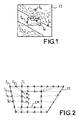
- Figure 1 shows an image of outlines extracted from a data image, which may be from an infrared camera, a video system, or any other image source.
- FIG. 1 illustrates an image of outlines extracted from an image obtained in any way: infrared image, active image. It contains image contour points, which correspond to the black pixels on this image, such as the points referenced I a , I b , I c , I d in FIG. 1. These contour points may be contour points of a target to be identified as the point I a, the outer points to the contour of the target to be identified, such points I b and I c or points of an inner contour to the target to be identified, such as the point I of .
- the proximity measuring method comprises a step of unambiguous pairing of each of the model contour points to zero or a single image contour point and a step of assigning a local proximity note to each point of the image. model outline, representing the proximity of this model outline point with the image outline.
- This method entails that, in step a), two information items are memorized for each image contour point: the coordinates of the associated model contour point and the corresponding distance between the two associated points, to perform step b) - d matching on the basis of these two pieces of information.
- the distance considered is the Euclidean distance, of which a true measurement is measured or a discrete measurement according to the calculation methods used.
- the use of a chamfer method makes it possible in a known manner to accelerate the calculation time, uses a discrete measurement of the Euclidean distance.
- Steps a) - and b) - are illustrated in Figures 2 and 3.
- Step a) -. is illustrated in FIG. 2.
- the proximity of the image contour points CI to the model contour CM is evaluated to associate with each contour point a closest model contour point.
- the evaluation of the nearest model contour point consists in finding the lowest distance d between this image contour point and an outline point. model.
- this evaluation leads to associating the point M 1 of model contour CM with the point I 1 of the image contour C1.
- a same model contour point may be associated with different image contour points.
- the point M 1 of the model contour CM has been associated with the image contour points I 1 , I 2 , I 3 .
- Step b) - is illustrated in Figure 3. It consists for each model contour point to select from the image contour points associated with it in the first step a), the nearest contour point image of the model outline point.
- the dotted lines represent the mapping of image contour points with model contour points according to the first step a). For each model contour point, there is thus 0, one or n associated contour points according to this step a). For example, for the image contour point M 15 , there are 3 associated image contour points: l 24 , l 28 , and l 29 .
- Step b) consists in keeping only the nearest image point, when it exists, among the image contour points associated with the same model contour point and in evaluating the local proximity note of this model contour point. to the image contour on the basis of the matching (contour point model-contour point image) thus performed.
- the pairing point M i (pattern) with point l k (image) is the following: (M 10 , zero point image); (M 11 , 1, 20 ); (M 12 , 12 ); (M 13 , 22 ); (M 15 , 1, 24 ).
- the point-to-point matching step provides for each point M i of model contour M i matched to a single image contour point I k , a measurement of proximity of this point M i to the image contour.
- This measure of proximity of the point M i can be written as:
- Dist (M i ) d (M i , I k ), where d (M i , I k ) is a true or approximate measure of the Euclidean distance between the paired points. It is expressed in number of pixels.
- the last step of the process is then to determine the overall score for the model, by averaging the local scores of all the points of the model outline.
- the model contour is evaluated as being all the closer to an image contour that the overall rating assigned to it is high.
- FIGS. 4a and 4b we superimposed on an image 1 comprising a target C, a first model MOD 1 ( Figure 4a) and a second model MOD 2 ( Figure 4b).
- the first model MOD 1 corresponds in the example to the target to detect on which it is perfectly positioned. It leads to a hypothesis retained.
- the second model corresponds to another type of target. But with a method according to the state of the art, the hypothesis will be retained, because of the presence of contour points not belonging to the contour of the target, but actually belonging to the bottom, or to contour points internal.
- the evaluation of the local proximity note of each model contour point is a function of the distance d between this point and the paired image contour point according to the invention.
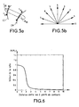
- the evaluation of the proximity of two points comprises taking into account the orientation class at the points I 20 and M 30 of the pair P considered.
- This class is typically defined by the orientation of the tangent of the contour at the point considered: in FIG. 5a, the tangent t I is represented at the image contour point I 20 of the image contour CI and the tangent t M at the contour point model M 30 of the contour model CM.
- proximity measurement is a continuous function of position and orientation. This limits the weight of the orientation, which can be erroneously estimated.
- the orientation class is taken into account in the step of associating the point-to-point matching process, by not allowing the association (and therefore the pairing) only between points of the same class.
- the proximity measure Dist (M i ) is equal to the distance between the paired points M i and l k .
- the attribution of the local proximity note N (M i ) of a model contour point M i as a function of the proximity measurement according to the invention must contribute to the robustness of the identification method.
- a practical implementation of a proximity measurement method according to the invention can use so-called chamfer calculation methods. These chamfer methods are very efficient in terms of computation time and are widely used in many areas of image processing including that of shape recognition.
- a classical chamfer method allows to map to a contour, a map with two inputs x and y corresponding to the coordinates of a given point, and an output, which is the lowest distance from this point (x, y) to the outline. In other words, the lowest distance from the point (x, y) to the contour mapped by contour lines is evaluated.
- This known method of chamfer is generally used to apply the Hausdorff measurement method. In this case, the chamfer method is applied to the image contour, making it possible to determine for each point (x, y) of model contour, the smallest distance to the image contour.
- the chamfer method must be applied differently.
- the aim is to measure the smallest distance from an image contour point to the model contour. This involves applying the chamfering method no longer to the image contour, but to each of the model contours.
- the calculation of the chamfer map of a model contour is independent of the extracted contour image to be analyzed. These calculations can be done once and for all and stored, to be used when the time comes, in real time, for the analysis of a given contour image.
- the chamfer map of the model contour must output a first information which is the distance between the two associated points, and a second information which is the identification of the model contour point associated with this distance.
- This second piece of information is necessary because it will enable the pairing stage to determine all the image contour points associated with the same model contour point, and to automatically deduce the proximity measure. by the first associated information.
- a rapid calculation method comprises the calculation of a chamfer map for each model contour, said map giving as a function of the two inputs x and y corresponding to the coordinates of an image contour point, an information S 0 (x, y) identifying the model contour point reached by the lowest distance measurement, and information S 1 (x, y) corresponding to the value of this measurement.
- This method does not make it possible to correct the distance measure Dist (M i ) of a model contour point M i as a function of the orientation class of this point and of the paired image contour point I k .
- the step of associating with each contour point of a model contour point then comprises, for each image contour point, the preliminary determination of the orientation class of this point, and the selection of the chamfer card. of the model contour in the corresponding orientation class.
- the method according to the invention is applied to all model contours by scanning each time on the entire image.
- model contour to be understood as the model contour in a given position
- probability measure of similarity of this model contour to the image contour is obtained.
- hypotheses a selection of hypotheses is then established.
- hypothesis is meant a model contour (that is to say a target, from a certain point of view) in a determined position in the image.
- the selection is typically obtained by retaining the most probable assumptions corresponding to an overall score obtained above a decision threshold.
- This threshold is preferably set at 0.6.
- Another aspect of the invention makes it possible to improve this last point.
- the problem more particularly considered here is due to the fact that, according to certain angles of view, for certain orientations, two targets may have relatively similar shapes, similar to the meaning of the overall score ⁇ assigned according to the invention.
- Some parts of a model outline are therefore more informative than others with respect to another model outline.
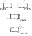
- FIG. 7d thus shows an IC image contour corresponding to an image of extracted contours.
- Two models CM 1 and CM 2 shown respectively in Figure 7a and Figure 7b, are found close to the meaning of the invention of this image contour.
- the basic idea of the improvement according to the invention consists in considering the two hypotheses which are superimposed, and in weighting the local note of each point of a model contour, established in the measure of proximity of this model contour to the image contour. , by a quantity of information representing the local difference at this point, with the other model contour.
- the overall score ⁇ 1 associated with the model contour CM 1 which measures the probability of similarity of this model contour CM 1 to the image contour CI is obtained by weighting each of the local notes. More precisely, the local proximity note N (M1 i ) of each point M1 i of the model contour CM1 is weighted by a factor representative at this point of the quantity of discriminant information that it contains relative to the other contour. CM model 2 . This amount of information contained in a point M1 i of the model contour CM 1 must be all the more high since this point is far from the other model contour CM 2 : it is the very definition of the proximity measurement in this Dist point (M1 i ) according to the method of the invention.
- M2 j is a point of the model contour CM2 j paired with the point M1 i according to the proximity measuring method of the invention.
- M2 j is a point of the model contour CM2 j paired with the point M1 i according to the proximity measuring method of the invention.
- the greater the distance to the matched point the greater the amount of information at this point.
- This is schematically represented in Figure 7c.
- the amount of information X (M1) is large, corresponding to the distance a in Fig.
- the weighting method is applied to the points of the second contour CM 2 , inverting the role of the first and second contours, that is to say using the method of measuring the proximity of the second contour CM 2 to the first contour CM 1 : we obtain the amount of information X (M2 j ) of each point M2 j of the second contour CM 2 relative to the first contour CM 1 .
- the local proximity note N (M2 j ) of each point M2 j is weighted by the associated quantity of information X (M2 j ).
- the discrimination process is applied two by two.
- the invention describes a method for measuring the proximity of a second contour to a first contour, according to which each point M i of the second contour is matched with one or zero points of the first contour, giving a distance measurement Dist (M i ) at this point.
- An automatic target identification method applies this proximity measurement process to determine the measure of proximity of each point of a model contour, applied as a second contour, to an image contour, applied as the first contour. He deduces for each point of the model contour, a local note of proximity and for the model contour, a global note, giving a measure of likelihood of similarity to the image contour.
- the automatic identification method thus determines the overall score associated with each of the model contours of a collection (with as many different model contours as different 3D models and points of view considered for each 3D model).
- the invention applies a criterion of selection of hypotheses, retaining as probable hypothesis, each of the model contours whose overall score is greater than the threshold.
- the model contours of the collection correspond to a selection of hypotheses, resulting from another process, for example, resulting from a Hausdorff measurement.
- the automatic identification method then applies the weighting method to each pair of hypotheses which are superimposed among the assumptions retained, in order to obtain for the model contour associated with each hypothesis a weighted overall score.
- the method of measuring proximity applying it a first time, to measure the amount of information associated with each point of the contour of the first hypothesis, applied as a second contour, relative to the outline of the second hypothesis. applied as the first contour, and calculate the overall rating associated by averaging the weighted local scores.
- It applies the proximity measurement method a second time to measure the amount of information associated with each point of the contour of the second hypothesis applied as the second contour, relative to the contour of the first hypothesis applied as the first contour, and to calculate the overall score. associated by averaging the weighted local scores.
- the identification system selects the best hypothesis. If the hypotheses that are superimposed are greater than two, the automatic identification system applies this weighting two by two, to retain each time the best hypothesis.
- an automatic identification system according to the invention to a first selection of hypotheses obtained from another automatic identification process, such as a process using the Hausdorff measurement, does not change. identification performance, but advantageously saves computing time.
- the invention which has just been described makes it possible to appreciably improve the robustness and the discrimination of an automatic identification system which implements it. It applies to the military field, but more generally, to any domain using pattern recognition as compared to a series of models.
Landscapes
- Engineering & Computer Science (AREA)
- Theoretical Computer Science (AREA)
- Computer Vision & Pattern Recognition (AREA)
- Physics & Mathematics (AREA)
- General Physics & Mathematics (AREA)
- Multimedia (AREA)
- Evolutionary Computation (AREA)
- Software Systems (AREA)
- Computing Systems (AREA)
- Databases & Information Systems (AREA)
- Health & Medical Sciences (AREA)
- General Health & Medical Sciences (AREA)
- Medical Informatics (AREA)
- Artificial Intelligence (AREA)
- Image Analysis (AREA)
- Image Processing (AREA)
- Length Measuring Devices By Optical Means (AREA)
- Control Of Position, Course, Altitude, Or Attitude Of Moving Bodies (AREA)
- Flow Control (AREA)
- Control Of Driving Devices And Active Controlling Of Vehicle (AREA)
- Length Measuring Devices With Unspecified Measuring Means (AREA)
Claims (19)
- Automatisiertes Messverfahren der Nähe einer aus einem Bild extrahierten zweiten Kontur (CM) zu einer ersten Kontur (CI), das für jeden Punkt (Ik) der ersten Kontur einen Schritt der Zuordnung zu einem Punkt (Mi) der zweiten Kontur aufweist, der als der nächstliegende bestimmt wird, dadurch gekennzeichnet, dass es einen Schritt der Paarbildung jedes Punkts der zweiten Kontur mit einem Punkt oder Null Punkt der ersten Kontur durch Bestimmung des nächstliegenden Punkts der ersten Kontur aus der Gesamtheit der dem Punkt der zweiten Kontur zugeordneten Punkte der ersten Kontur aufweist.
- Verfahren nach Anspruch 1, dadurch gekennzeichnet, dass die Bestimmung eines Punkts, der einem gegebenen Punkt am nächsten liegt, auf einer echten oder diskreten Messung des euklidischen Abstands zwischen den beiden Punkten beruht.
- Verfahren nach Anspruch 2, dadurch gekennzeichnet, dass es einen Schritt der Zuweisung einer Näherungsmessung Dist(Mi) jedes Punkts Mi der zweiten Kontur (CM) zur ersten Kontur (CI) aufweist, der auf der Messung des Abstands dieses Punkts von dem Punkt der ersten Kontur beruht, mit dem er gepaart ist.
- Verfahren nach Anspruch 3, dadurch gekennzeichnet, dass die Abstandsmessung eine korrigierte Messung in Abhängigkeit von der Differenz der Ausrichtungsklasse der Punkte des betrachteten Paars ist.
- Verfahren nach einem der Ansprüche 1 bis 3, dadurch gekennzeichnet, dass im Schritt der Zuordnung zu jedem Punkt der ersten Kontur von Null oder einem Punkt der zweiten Kontur der am nächsten liegende Punkt unter den Punkten der zweiten Kontur zugeordnet wird, die die gleiche Ausrichtungsklasse wie der Punkt der ersten Kontur haben.
- Verfahren nach einem der Ansprüche 1, 2, 3 oder 5, dadurch gekennzeichnet, dass der Zuordnungsschritt eine Abschrägungskarte der zweiten Kontur verwendet, durch die an jedem Punkt der ersten Kontur mit den Koordinaten x und y, die am Eingang angelegt werden, die Karte am Ausgang eine Identifizierung (S0(x,y)) des zugeordneten Punkts der zweiten Kontur und eine Messung (S1(x,y)) des Abstands zwischen den beiden so zugeordneten Punkten liefert.
- Verfahren nach Anspruch 6 in Verbindung mit Anspruch 5, dadurch gekennzeichnet, dass der zweiten Kontur eine Abschrägungskarte pro Ausrichtungsklasse zugeordnet ist, und dass für jeden Punkt der ersten Kontur der Zuordnungsschritt einen Schritt der Bestimmung der Klasse des Punkts der ersten Kontur aufweist, um die Koordinaten (x,y) dieses Punkts an den Eingang der Abschrägungskarte anzulegen, die dieser Ausrichtungsklasse entspricht.
- Verfahren nach einem der Ansprüche 4 bis 7, dadurch gekennzeichnet, dass es acht Ausrichtungsklassen verwendet.
- Verfahren zur automatischen Identifizierung von Zielen in einem Bild von extrahierten Konturen (CI), das von einer Bildkontur definiert wird, dadurch gekennzeichnet, dass es ein Verfahren der Näherungsmessung nach einem der Ansprüche 1 bis 8 anwendet, indem es als zweite Kontur eine Modellkontur (CM) und als erste Kontur die Bildkontur (CI) anwendet, um die Näherungsmessung Dist(Mi) jedes Punkts der Modellkontur zur Bildkontur zu erhalten.
- Identifizierungsverfahren nach Anspruch 9, dadurch gekennzeichnet, dass es die Zuweisung einer lokalen Näherungs-Note (N(Mi) zu jedem Punkt Mi der Modellkontur in Abhängigkeit von der Näherungsmessung Dist (Mi) dieses Punkts gemäß den folgenden Kriterien aufweist:- N(Mi) hat einen Wert zwischen 0 und 1,- N(Mi) = 0, wenn der Punkt mit Null Punkt der ersten Kontur gepaart ist;- N(Mi) = 1, wenn das Näherungsmaß gleich Null ist;- N(Mi) hat einen Wert nahe 1, wenn das Näherungsmaß zwischen 0 und 1 Pixel liegt;- N(Mi) nimmt sehr schnell gegen 0 ab, sobald das Näherungsmaß größer wird als 1 Pixel;- N(Mi) nimmt gemäß einer Kurve ab, die einen Wendepunkt in der Nähe eines Näherungsmaßes nahe 2 Pixel aufweist;- N(Mi) hat einen Wert praktisch gleich Null, sobald das Näherungsmaß größer wird als 3 Pixel.
- Identifizierungsverfahren, nach dem vorhergehenden Anspruch, dadurch gekennzeichnet, dass die Funktion der Zuweisung der Näherungs-Note zum Punkt Mi folgendermaßen ausgedrückt wird:

- Identifizierungsverfahren nach Anspruch 10 oder 11, dadurch gekennzeichnet, dass es einen Schritt der Messung einer globalen Note η gleich dem Mittelwert der Näherungs-Noten, bezogen auf die Anzahl von Punkten der Modellkontur (CM), aufweist.
- Identifizierungsverfahren nach einem der Ansprüche 9 bis 12, dadurch gekennzeichnet, dass es nacheinander auf jede der Modellkonturen einer Kollektion von Modellkonturen angewendet wird.
- Identifizierungsverfahren nach Anspruch 13, dadurch gekennzeichnet, dass die Kollektion von einem anderen Verfahren der Identifizierung von Zielen erhalten wird, z.B. einem Verfahren, das eine Hausdorff-Abstandsmessung verwendet.
- Identifizierungsverfahren nach Anspruch 13 oder 14, dadurch gekennzeichnet, dass es einen Schritt der Auswahl von Hypothesen durch Vergleich mit einem Schwellwert jeder der globalen Noten η aufweist, die jeder der Modellkonturen zugewiesen sind.
- Identifizierungsverfahren nach Anspruch 15, dadurch gekennzeichnet, dass der Schwellwert auf 0,6 festgelegt ist.
- Identifizierungsverfahren nach einem der Ansprüche 15 oder 16, dadurch gekennzeichnet, dass es einen Schritt der Unterscheidung zwischen Hypothesen von Modellkonturen aufweist, die sich überlagern, mit für jedes Paar einer ersten Kontur-Hypothese (CM1) und einer zweiten Kontur-Hypothese (CM2), die sich überlagern, mit einem Schritt der Gewichtung der globalen Note, die jeder der Modellkonturen zugewiesen ist, wobei der Gewichtungsschritt die Anwendung des Verfahrens zur Näherungsmessung nach einem der Ansprüche 3 bis 8 aufweist:- a indem als zweite Kontur die Kontur der ersten Hypothese und als erste Kontur die Kontur der zweiten Hypothese angewendet wird, wobei die Näherungsmessung Dist(M1i), die für jeden Punkt (M1i) der Kontur (CM1) der ersten Hypothese erhalten wird, als Gewichtungsfaktor X(M1i) der lokalen Näherungs-Note (N(M1i)) dieses Punkts an die Bildkontur (CI) angewendet wird, und daraus die der ersten Kontur-Hypothese zugeordnete globale Note (η1) abgeleitet wird, die ihren Abstand zur Bildkontur darstellt, indem der Mittelwert der gewichteten lokalen Noten berechnet wird,- b indem als zweite Kontur die Kontur der zweiten Hypothese und als erste Kontur die Kontur der ersten Hypothese angewendet wird, wobei die Näherungsmessung Dist(M2j), die für jeden Punkt (M2j) der Kontur (CM2) der ersten Hypothese erhalten wird, als Gewichtungsfaktor X(M2j) der lokalen Näherungs-Note (N(M2j)) dieses Punkts an die Bild-Kontur (CI) angewendet wird, und daraus die der ersten Kontur-Hypothese zugeordnete globale Note (η2) abgeleitet wird, die ihren Abstands zur Bildkontur darstellt, indem der Mittelwert der gewichteten lokalen Noten berechnet wird.
- Identifizierungsverfahren nach Anspruch 17, dadurch gekennzeichnet, dass es als beste Modellkontur-Hypothese unter mehreren sich überlagernden Hypothesen diejenige nimmt, der die beste globale Note zugeordnet ist.
- System zur automatischen Identifizierung eines Gegenstands in einem Bild von Konturen, mit einer Datenbasis, die Modelle von bestimmten zu erkennenden Gegenständen enthält, und mit Rechenmitteln, wobei die Rechenmittel konfiguriert sind, um Konturen zu vergleichen, dadurch gekennzeichnet, dass die Rechenmittel konfiguriert sind, um die Schritte eines Identifizierungsverfahrens nach einem der Ansprüche 9 bis 18 durchzuführen.
Applications Claiming Priority (2)
| Application Number | Priority Date | Filing Date | Title |
|---|---|---|---|
| FR0308707A FR2857771B1 (fr) | 2003-07-17 | 2003-07-17 | Systeme d'identification automatique de cibles |
| PCT/EP2004/051476 WO2005017818A1 (fr) | 2003-07-17 | 2004-07-13 | Procede de mesure de proximite de deux contours et systeme d'identification automatique de cibles |
Publications (2)
| Publication Number | Publication Date |
|---|---|
| EP1646967A1 EP1646967A1 (de) | 2006-04-19 |
| EP1646967B1 true EP1646967B1 (de) | 2007-01-31 |
Family
ID=33548197
Family Applications (1)
| Application Number | Title | Priority Date | Filing Date |
|---|---|---|---|
| EP04766207A Expired - Lifetime EP1646967B1 (de) | 2003-07-17 | 2004-07-13 | Verfahren zur messung des naheverhältnisses zweier konturen und system zur automatischen zielidentifikation |
Country Status (10)
| Country | Link |
|---|---|
| US (1) | US7783112B2 (de) |
| EP (1) | EP1646967B1 (de) |
| JP (1) | JP4745966B2 (de) |
| KR (1) | KR20060056949A (de) |
| AT (1) | ATE353153T1 (de) |
| DE (1) | DE602004004594T2 (de) |
| ES (1) | ES2281001T3 (de) |
| FR (1) | FR2857771B1 (de) |
| IL (1) | IL173125A (de) |
| WO (1) | WO2005017818A1 (de) |
Families Citing this family (10)
| Publication number | Priority date | Publication date | Assignee | Title |
|---|---|---|---|---|
| US7965890B2 (en) * | 2007-01-05 | 2011-06-21 | Raytheon Company | Target recognition system and method |
| US9250324B2 (en) | 2013-05-23 | 2016-02-02 | GM Global Technology Operations LLC | Probabilistic target selection and threat assessment method and application to intersection collision alert system |
| US9582739B2 (en) * | 2014-11-18 | 2017-02-28 | Harry Friedbert Padubrin | Learning contour identification system using portable contour metrics derived from contour mappings |
| CN104463866B (zh) * | 2014-12-04 | 2018-10-09 | 无锡日联科技有限公司 | 一种基于轮廓随机采样的局部形状匹配方法 |
| CN104574519B (zh) * | 2015-01-31 | 2017-05-31 | 华北水利水电大学 | 多源居民地面要素的免阈值自动稳健匹配方法 |
| MX364903B (es) * | 2015-05-16 | 2019-05-10 | Tata Consultancy Services Ltd | Procedimiento y sistema de comprobación del cumplimiento de un planograma basado en análisis visual. |
| CN105678844B (zh) * | 2016-01-06 | 2018-04-24 | 东南大学 | 一种基于地物散乱点逐点增加的轮廓构建方法 |
| FR3086161B1 (fr) * | 2018-09-24 | 2021-03-12 | Interactif Visuel Systeme I V S | Determination automatique des parametres necessaires a la realisation de lunettes. |
| US11022972B2 (en) * | 2019-07-31 | 2021-06-01 | Bell Textron Inc. | Navigation system with camera assist |
| CN115273091B (zh) * | 2022-06-23 | 2025-10-28 | 上海芙艾管理咨询有限公司 | 一种热玛吉主机反馈信号的获取方法及系统 |
Family Cites Families (3)
| Publication number | Priority date | Publication date | Assignee | Title |
|---|---|---|---|---|
| US5321770A (en) * | 1991-11-19 | 1994-06-14 | Xerox Corporation | Method for determining boundaries of words in text |
| JPH05225335A (ja) * | 1992-02-17 | 1993-09-03 | Nippon Telegr & Teleph Corp <Ntt> | 物体の領域切り出し装置 |
| US7158677B2 (en) * | 2002-08-20 | 2007-01-02 | National Instruments Corporation | Matching of discrete curves under affine transforms |
-
2003
- 2003-07-17 FR FR0308707A patent/FR2857771B1/fr not_active Expired - Fee Related
-
2004
- 2004-07-13 DE DE602004004594T patent/DE602004004594T2/de not_active Expired - Lifetime
- 2004-07-13 AT AT04766207T patent/ATE353153T1/de not_active IP Right Cessation
- 2004-07-13 KR KR1020067001165A patent/KR20060056949A/ko not_active Withdrawn
- 2004-07-13 EP EP04766207A patent/EP1646967B1/de not_active Expired - Lifetime
- 2004-07-13 WO PCT/EP2004/051476 patent/WO2005017818A1/fr not_active Ceased
- 2004-07-13 US US10/564,762 patent/US7783112B2/en not_active Expired - Fee Related
- 2004-07-13 ES ES04766207T patent/ES2281001T3/es not_active Expired - Lifetime
- 2004-07-13 JP JP2006519928A patent/JP4745966B2/ja not_active Expired - Fee Related
-
2006
- 2006-01-12 IL IL173125A patent/IL173125A/en active IP Right Grant
Also Published As
| Publication number | Publication date |
|---|---|
| IL173125A (en) | 2010-11-30 |
| US20060193493A1 (en) | 2006-08-31 |
| DE602004004594T2 (de) | 2007-11-15 |
| ES2281001T3 (es) | 2007-09-16 |
| FR2857771A1 (fr) | 2005-01-21 |
| IL173125A0 (en) | 2006-06-11 |
| JP2009514057A (ja) | 2009-04-02 |
| WO2005017818A1 (fr) | 2005-02-24 |
| KR20060056949A (ko) | 2006-05-25 |
| ATE353153T1 (de) | 2007-02-15 |
| US7783112B2 (en) | 2010-08-24 |
| DE602004004594D1 (de) | 2007-03-22 |
| FR2857771B1 (fr) | 2005-09-23 |
| JP4745966B2 (ja) | 2011-08-10 |
| EP1646967A1 (de) | 2006-04-19 |
Similar Documents
| Publication | Publication Date | Title |
|---|---|---|
| US11170224B2 (en) | Keyframe-based object scanning and tracking | |
| EP2724203B1 (de) | Erzeugung von kartendaten | |
| CN111126393A (zh) | 车辆外观改装判断方法、装置、计算机设备及存储介质 | |
| EP2786314B1 (de) | Verfahren und vorrichtung zur verfolgung eines objekts in einer folge von mindestens zwei bildern | |
| FR3019359A1 (fr) | Procede de determination d'un etat d'obstruction d'au moins une camera embarquee dans un systeme stereoscopique | |
| CN116563279B (zh) | 基于计算机视觉的量测开关检测方法 | |
| FR3025898A1 (fr) | Procede et systeme de localisation et de cartographie | |
| EP3614306B1 (de) | Verfahren zur gesichtslokalisierung und -identifizierung und zur haltungsbestimmung anhand einer 3d-ansicht | |
| WO2006058986A2 (fr) | Procede d'identification d'un individu a partir de fragments d'image | |
| FR2857771A1 (fr) | Systeme d'identification automatique de cibles | |
| EP3608836B1 (de) | Verfahren zum erfassen eines fingerabdruck-bilds | |
| EP2710513A1 (de) | Verfahren zum suchen nach parametrisierten konturen für den vergleich von iriden | |
| EP3567521A1 (de) | Biometrisches erkennungsverfahren anhand der iris | |
| EP0863488A1 (de) | Verfahren zur Detektion der Höhenkonturen in zwei stereoskopischen Bildern | |
| EP3888000B1 (de) | Vorrichtung und verfahren zur authentifizierung eines individuums | |
| FR2979727A1 (fr) | Identification par reconnaissance d'iris | |
| EP3264329A1 (de) | Verfahren und vorrichtung zur detektion von betrug durch überprüfung mit zwei verschiedenen fokalzonen bei der automatischen erkennung eines gesichts | |
| Mayer et al. | Improved forgery detection with lateral chromatic aberration | |
| EP2474937A1 (de) | Elektronisches Authentifizierungsverfahren einer handschriftlichen Unterschrift, Modul-und entsprechendes Computerprogramm | |
| EP3839887B1 (de) | Verfahren und vorrichtung zur kalibrierung eines kollaborativen nachverfolgungssystems von zielen | |
| WO2021209412A1 (fr) | Procede de detection d'attaque par presentation pour des empreintes digitales | |
| Ruscio et al. | Dealing with Feature Correspondence in Visual Odometry for Underwater Applications | |
| EP4432256B1 (de) | Verfahren mit inter-pixel-abständen im zusammenhang mit fingerabdrücken | |
| EP4432255B1 (de) | Verfahren zur schätzung eines inter-bit-abstandes im zusammenhang mit einem fingerabdruck | |
| CN120318312B (zh) | 一种空间目标主体形心定位方法及系统 |
Legal Events
| Date | Code | Title | Description |
|---|---|---|---|
| PUAI | Public reference made under article 153(3) epc to a published international application that has entered the european phase |
Free format text: ORIGINAL CODE: 0009012 |
|
| 17P | Request for examination filed |
Effective date: 20060113 |
|
| AK | Designated contracting states |
Kind code of ref document: A1 Designated state(s): AT BE BG CH CY CZ DE DK EE ES FI FR GB GR HU IE IT LI LU MC NL PL PT RO SE SI SK TR |
|
| RTI1 | Title (correction) |
Free format text: METHOD FOR MEASURING THE PROXIMITY OF TWO CONTOURS AND SYSTEM FOR AUTOMATIC TARGET IDENTIFICATION |
|
| GRAP | Despatch of communication of intention to grant a patent |
Free format text: ORIGINAL CODE: EPIDOSNIGR1 |
|
| DAX | Request for extension of the european patent (deleted) | ||
| GRAS | Grant fee paid |
Free format text: ORIGINAL CODE: EPIDOSNIGR3 |
|
| GRAA | (expected) grant |
Free format text: ORIGINAL CODE: 0009210 |
|
| AK | Designated contracting states |
Kind code of ref document: B1 Designated state(s): AT BE BG CH CY CZ DE DK EE ES FI FR GB GR HU IE IT LI LU MC NL PL PT RO SE SI SK TR |
|
| PG25 | Lapsed in a contracting state [announced via postgrant information from national office to epo] |
Ref country code: SI Free format text: LAPSE BECAUSE OF FAILURE TO SUBMIT A TRANSLATION OF THE DESCRIPTION OR TO PAY THE FEE WITHIN THE PRESCRIBED TIME-LIMIT Effective date: 20070131 Ref country code: PL Free format text: LAPSE BECAUSE OF FAILURE TO SUBMIT A TRANSLATION OF THE DESCRIPTION OR TO PAY THE FEE WITHIN THE PRESCRIBED TIME-LIMIT Effective date: 20070131 Ref country code: AT Free format text: LAPSE BECAUSE OF FAILURE TO SUBMIT A TRANSLATION OF THE DESCRIPTION OR TO PAY THE FEE WITHIN THE PRESCRIBED TIME-LIMIT Effective date: 20070131 Ref country code: IE Free format text: LAPSE BECAUSE OF FAILURE TO SUBMIT A TRANSLATION OF THE DESCRIPTION OR TO PAY THE FEE WITHIN THE PRESCRIBED TIME-LIMIT Effective date: 20070131 Ref country code: DK Free format text: LAPSE BECAUSE OF FAILURE TO SUBMIT A TRANSLATION OF THE DESCRIPTION OR TO PAY THE FEE WITHIN THE PRESCRIBED TIME-LIMIT Effective date: 20070131 |
|
| REG | Reference to a national code |
Ref country code: GB Ref legal event code: FG4D Free format text: NOT ENGLISH |
|
| REG | Reference to a national code |
Ref country code: CH Ref legal event code: EP |
|
| REG | Reference to a national code |
Ref country code: IE Ref legal event code: FG4D Free format text: LANGUAGE OF EP DOCUMENT: FRENCH |
|
| REF | Corresponds to: |
Ref document number: 602004004594 Country of ref document: DE Date of ref document: 20070322 Kind code of ref document: P |
|
| PG25 | Lapsed in a contracting state [announced via postgrant information from national office to epo] |
Ref country code: BG Free format text: LAPSE BECAUSE OF FAILURE TO SUBMIT A TRANSLATION OF THE DESCRIPTION OR TO PAY THE FEE WITHIN THE PRESCRIBED TIME-LIMIT Effective date: 20070430 |
|
| GBT | Gb: translation of ep patent filed (gb section 77(6)(a)/1977) |
Effective date: 20070410 |
|
| REG | Reference to a national code |
Ref country code: SE Ref legal event code: TRGR |
|
| REG | Reference to a national code |
Ref country code: GR Ref legal event code: EP Ref document number: 20070401303 Country of ref document: GR |
|
| PG25 | Lapsed in a contracting state [announced via postgrant information from national office to epo] |
Ref country code: PT Free format text: LAPSE BECAUSE OF FAILURE TO SUBMIT A TRANSLATION OF THE DESCRIPTION OR TO PAY THE FEE WITHIN THE PRESCRIBED TIME-LIMIT Effective date: 20070702 |
|
| REG | Reference to a national code |
Ref country code: ES Ref legal event code: FG2A Ref document number: 2281001 Country of ref document: ES Kind code of ref document: T3 |
|
| REG | Reference to a national code |
Ref country code: IE Ref legal event code: FD4D |
|
| PG25 | Lapsed in a contracting state [announced via postgrant information from national office to epo] |
Ref country code: SK Free format text: LAPSE BECAUSE OF FAILURE TO SUBMIT A TRANSLATION OF THE DESCRIPTION OR TO PAY THE FEE WITHIN THE PRESCRIBED TIME-LIMIT Effective date: 20070131 |
|
| PLBE | No opposition filed within time limit |
Free format text: ORIGINAL CODE: 0009261 |
|
| STAA | Information on the status of an ep patent application or granted ep patent |
Free format text: STATUS: NO OPPOSITION FILED WITHIN TIME LIMIT |
|
| PG25 | Lapsed in a contracting state [announced via postgrant information from national office to epo] |
Ref country code: CZ Free format text: LAPSE BECAUSE OF FAILURE TO SUBMIT A TRANSLATION OF THE DESCRIPTION OR TO PAY THE FEE WITHIN THE PRESCRIBED TIME-LIMIT Effective date: 20070131 Ref country code: RO Free format text: LAPSE BECAUSE OF FAILURE TO SUBMIT A TRANSLATION OF THE DESCRIPTION OR TO PAY THE FEE WITHIN THE PRESCRIBED TIME-LIMIT Effective date: 20070131 |
|
| 26N | No opposition filed |
Effective date: 20071101 |
|
| PG25 | Lapsed in a contracting state [announced via postgrant information from national office to epo] |
Ref country code: MC Free format text: LAPSE BECAUSE OF NON-PAYMENT OF DUE FEES Effective date: 20070731 |
|
| PG25 | Lapsed in a contracting state [announced via postgrant information from national office to epo] |
Ref country code: CY Free format text: LAPSE BECAUSE OF NON-PAYMENT OF DUE FEES Effective date: 20070713 |
|
| PG25 | Lapsed in a contracting state [announced via postgrant information from national office to epo] |
Ref country code: EE Free format text: LAPSE BECAUSE OF FAILURE TO SUBMIT A TRANSLATION OF THE DESCRIPTION OR TO PAY THE FEE WITHIN THE PRESCRIBED TIME-LIMIT Effective date: 20070131 |
|
| REG | Reference to a national code |
Ref country code: CH Ref legal event code: PL |
|
| PG25 | Lapsed in a contracting state [announced via postgrant information from national office to epo] |
Ref country code: CH Free format text: LAPSE BECAUSE OF NON-PAYMENT OF DUE FEES Effective date: 20080731 Ref country code: LI Free format text: LAPSE BECAUSE OF NON-PAYMENT OF DUE FEES Effective date: 20080731 |
|
| PG25 | Lapsed in a contracting state [announced via postgrant information from national office to epo] |
Ref country code: LU Free format text: LAPSE BECAUSE OF NON-PAYMENT OF DUE FEES Effective date: 20070713 |
|
| PG25 | Lapsed in a contracting state [announced via postgrant information from national office to epo] |
Ref country code: HU Free format text: LAPSE BECAUSE OF FAILURE TO SUBMIT A TRANSLATION OF THE DESCRIPTION OR TO PAY THE FEE WITHIN THE PRESCRIBED TIME-LIMIT Effective date: 20070801 Ref country code: TR Free format text: LAPSE BECAUSE OF FAILURE TO SUBMIT A TRANSLATION OF THE DESCRIPTION OR TO PAY THE FEE WITHIN THE PRESCRIBED TIME-LIMIT Effective date: 20070131 |
|
| REG | Reference to a national code |
Ref country code: FR Ref legal event code: PLFP Year of fee payment: 13 |
|
| REG | Reference to a national code |
Ref country code: FR Ref legal event code: PLFP Year of fee payment: 14 |
|
| REG | Reference to a national code |
Ref country code: FR Ref legal event code: PLFP Year of fee payment: 15 |
|
| PGFP | Annual fee paid to national office [announced via postgrant information from national office to epo] |
Ref country code: GR Payment date: 20200624 Year of fee payment: 17 Ref country code: FR Payment date: 20200625 Year of fee payment: 17 |
|
| PGFP | Annual fee paid to national office [announced via postgrant information from national office to epo] |
Ref country code: BE Payment date: 20200624 Year of fee payment: 17 |
|
| PGFP | Annual fee paid to national office [announced via postgrant information from national office to epo] |
Ref country code: NL Payment date: 20200715 Year of fee payment: 17 |
|
| PGFP | Annual fee paid to national office [announced via postgrant information from national office to epo] |
Ref country code: DE Payment date: 20200630 Year of fee payment: 17 Ref country code: FI Payment date: 20200709 Year of fee payment: 17 Ref country code: ES Payment date: 20200803 Year of fee payment: 17 Ref country code: GB Payment date: 20200707 Year of fee payment: 17 |
|
| PGFP | Annual fee paid to national office [announced via postgrant information from national office to epo] |
Ref country code: IT Payment date: 20200625 Year of fee payment: 17 Ref country code: SE Payment date: 20200710 Year of fee payment: 17 |
|
| REG | Reference to a national code |
Ref country code: DE Ref legal event code: R079 Ref document number: 602004004594 Country of ref document: DE Free format text: PREVIOUS MAIN CLASS: G06K0009640000 Ipc: G06V0030192000 |
|
| REG | Reference to a national code |
Ref country code: DE Ref legal event code: R119 Ref document number: 602004004594 Country of ref document: DE |
|
| REG | Reference to a national code |
Ref country code: FI Ref legal event code: MAE |
|
| REG | Reference to a national code |
Ref country code: NL Ref legal event code: MM Effective date: 20210801 |
|
| GBPC | Gb: european patent ceased through non-payment of renewal fee |
Effective date: 20210713 |
|
| REG | Reference to a national code |
Ref country code: BE Ref legal event code: MM Effective date: 20210731 |
|
| PG25 | Lapsed in a contracting state [announced via postgrant information from national office to epo] |
Ref country code: GB Free format text: LAPSE BECAUSE OF NON-PAYMENT OF DUE FEES Effective date: 20210713 Ref country code: FI Free format text: LAPSE BECAUSE OF NON-PAYMENT OF DUE FEES Effective date: 20210713 Ref country code: DE Free format text: LAPSE BECAUSE OF NON-PAYMENT OF DUE FEES Effective date: 20220201 |
|
| PG25 | Lapsed in a contracting state [announced via postgrant information from national office to epo] |
Ref country code: SE Free format text: LAPSE BECAUSE OF NON-PAYMENT OF DUE FEES Effective date: 20210714 Ref country code: NL Free format text: LAPSE BECAUSE OF NON-PAYMENT OF DUE FEES Effective date: 20210801 Ref country code: GR Free format text: LAPSE BECAUSE OF NON-PAYMENT OF DUE FEES Effective date: 20220207 Ref country code: FR Free format text: LAPSE BECAUSE OF NON-PAYMENT OF DUE FEES Effective date: 20210731 |
|
| PG25 | Lapsed in a contracting state [announced via postgrant information from national office to epo] |
Ref country code: IT Free format text: LAPSE BECAUSE OF NON-PAYMENT OF DUE FEES Effective date: 20210713 Ref country code: BE Free format text: LAPSE BECAUSE OF NON-PAYMENT OF DUE FEES Effective date: 20210731 |
|
| REG | Reference to a national code |
Ref country code: ES Ref legal event code: FD2A Effective date: 20220826 |
|
| PG25 | Lapsed in a contracting state [announced via postgrant information from national office to epo] |
Ref country code: ES Free format text: LAPSE BECAUSE OF NON-PAYMENT OF DUE FEES Effective date: 20210714 |
|
| P01 | Opt-out of the competence of the unified patent court (upc) registered |
Effective date: 20230529 |