EP1647201B1 - Bürstenringanordnung - Google Patents
Bürstenringanordnung Download PDFInfo
- Publication number
- EP1647201B1 EP1647201B1 EP04077736A EP04077736A EP1647201B1 EP 1647201 B1 EP1647201 B1 EP 1647201B1 EP 04077736 A EP04077736 A EP 04077736A EP 04077736 A EP04077736 A EP 04077736A EP 1647201 B1 EP1647201 B1 EP 1647201B1
- Authority
- EP
- European Patent Office
- Prior art keywords
- brush
- ring
- shaped
- mentioned
- core part
- Prior art date
- Legal status (The legal status is an assumption and is not a legal conclusion. Google has not performed a legal analysis and makes no representation as to the accuracy of the status listed.)
- Expired - Lifetime
Links
Images



Classifications
-
- A—HUMAN NECESSITIES
- A46—BRUSHWARE
- A46B—BRUSHES
- A46B13/00—Brushes with driven brush bodies or carriers
- A46B13/001—Cylindrical or annular brush bodies
- A46B13/003—Cylindrical or annular brush bodies made up of a series of annular brush rings; Annular brush rings therefor
-
- A—HUMAN NECESSITIES
- A46—BRUSHWARE
- A46B—BRUSHES
- A46B2200/00—Brushes characterized by their functions, uses or applications
- A46B2200/30—Brushes for cleaning or polishing
- A46B2200/3066—Brush specifically designed for use with street cleaning machinery
Definitions
- the invention relates to a ring-shaped brush comprising a number of brush-rings each consisting of a ring-shaped core part and a radially protruding brush part, which brush-rings can be axially fixed one after another on a shaft-shaped pick-up instrument of a sweeping machine, said ring-shaped core part comprising a number of deformations along its circumference.
- Such a brush is known by US 6,205,609 Bl.
- the flat surface of said ring-shaped core part is deformed such that a descending part is followed by a corresponding ascending part.
- a relatively equal brush thread division along the formed cylindrical surfaxe of the finished brush for a sweeping machine is obtained.
- the object of the invention is to raise this disadvantage and to provide an improved brush.
- each ring-shaped core part is shaped such that along its circumference a multiple set of deforming steps is present, each set comprising at least two descending steps followed by one ascending step.
- the advantage is, that as regards intensity of the brush surface, a very flexible adjustable brush ring assembly is created, which assembly can be used for very different, more or less intensive surfaces to be sweeped.
- the economy is also in the benefit, because by adjustment, the surface to be sweeped can mechanically be less affected and for lighter sweeping work, one can use less brush rings for the cylindrical brush ring assembly.
- n is at least 3 and with larger diameters preferably 5 and more, in which the mentioned ring-shaped core part is applied rotation fixed by means of an axial catch pin and groove construction along the radial inner circumference of the ring-shaped core part and along the radial outer circumference of the mentioned shaft-shaped pick-up instrument.
- the device according to the invention is further developed in such a way, that the mentioned ring-shaped brushes, placed on the shaft-shaped pick-up instrument of the sweeping machine can be locked at the ends with a fast mountable flange or disc construction.
- the advantage is a very handy and simple catch pin- and groove construction to mount and lock the separate brush rings in the required position onto the shaft-shaped pick-up instrument.
- Figure 1 shows a front view in oblique projection of the most dense stacking of the core part 2 of the separate brush ring 1 (see figure 4), in which the radially protruding fibres 7 (see figure 4) are left out.
- the core part 2 is deformed each time in at least two steps or positions 5-4 and 4-3 descending and each time in one step 3-5 ascending almost vertical to the flat surface to the original ring-shaped core part 2.
- the rotation fixation of the core parts 2 and 2 1 is in this embodiment constructed by the centric protruding instrument or cams or catch pins 6, which stick into the not shown axial grooves of the shaft-shaped pick-up instrument.
- the mentioned axial grooves are applied over a suitable angle dependant on the value n on or over the shaft-shaped pick-up instrument in order to create the positions of the core parts 2 and 2 1 to respectively the most dense, medium and most open brush or by more steps into even more positions.
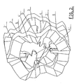
- Figure 2 shows the most open stacked brush rings in oblique projection, as also shown in figure 3C. At the most open brush a minimum quantity of brush rings 1 come onto the not shown shaft-shaped pick-up instrument of the sweeping machine.
- Figures 3A, 3B and 3C show in side view along the circumference of the brush ring 1 (see also figure 4), the most dense stacking (figure 3A), the medium stacking (figure 3B) and the most open stacking of the core parts 2 and 2 1 of the brush rings 1 at an n of 3, in which n shows the number of deformations of the descending and ascending steps along the circumference vertical onto the brush surface of the core part 2, 2 1 .
- Figure 4 shows a front view of the complete brush ring 1, in which the core part 2, 2 1 is shown in steps with the same indication numbers of steps 5-4, 4-3 and 3-5 or 5 1 -4 1 , 4 1 -3 1 and 3 1 -5 1 .
- the core part 2, 2 1 with the radial brush part 7 is mostly made as a whole of plastic, such as, for example, polypropylene.
- Figure 5 shows over the line V-V of figure 4 a cross-section of the brush ring 1 according to a preferred embodiment of the invention. The different steps and parts are each time indicated with the same numbers.
- Figure 6 shows a front view of the core part 2 of the brush ring 1 only, in which the different steps of 5-4, 4-3 and 3-5 are shown along the circumference of the 20 mm broad edge. Also the catch pins 6, in this case 4 pieces, are shown.
- the successive core parts can be turned over suitable angles to lie against the different surfaces 5, 4 and 3, through which the catch pins 6 can be turned over the mentioned angles over the grooves in the shaft-shaped pick-up instrument, through which a suitable brush density s created.
- Figure 7 shows a side view over the line VII of figure 6 for clarification, in which the brush threads are left out.
Landscapes
- Brushes (AREA)
- Cleaning In General (AREA)
- Motor Or Generator Current Collectors (AREA)
- Turbine Rotor Nozzle Sealing (AREA)
Claims (10)
- Ringförmige Bürste mit einer Anzahl von Bürstenringen, von denen jeder aus einem ringförmigen Kernstück (2, 2') und einem radial abstehenden Bürstenteil (7) besteht, wobei die Bürstenringe axial nacheinander auf einem schaftförmigen Aufnahmeinstrument einer Kehrmaschine befestigt werden können, wobei das ringförmige Kernstück eine Anzahl von Deformationen entlang seines Umfangs umfasst,
dadurch gekennzeichnet, dass jedes ringförmige Kernstück so geformt ist, dass entlang seines Umfangs eine multiple Gruppe von (n) deformierenden Stufen vorhanden ist, wobei jede Gruppe aus mindestens zwei absteigenden Stufen (5-4, 4-3, 5'-4', 4'-3'), gefolgt von einer aufsteigenden Stufe (3-5, 3'-5'), besteht. - Gerät nach Anspruch 1, dadurch gekennzeichnet, dass n mindestens 3 beträgt, und - bei größeren Durchmessern - vorzugsweise 5 und mehr beträgt.
- Gerät nach Anspruch 1, dadurch gekennzeichnet, dass das ringförmige Kernstück (2, 2') rotationsfest mit Hilfe einer axialen Splint- und Nutkonstruktion entlang des radialen inneren Umfangs des ringförmigen Kernstücks (2, 2') und entlang des radialen äußeren Umfangs des erwähnten schaftförmigen Aufnahmeinstruments befestigt ist.
- Gerät nach Anspruch 1, dadurch gekennzeichnet, dass die Tiefe der absteigenden Stufen (5-4, 4-3 und 5'-4', 4'-3') zwischen 5 mm und 50 mm liegt, vorzugsweise zumeist bei 10 mm.
- Gerät nach Anspruch 1, dadurch gekennzeichnet, dass die Scheibendicke des ringförmigen Kernstücks (2, 2') zwischen 10 mm und 60 mm liegt, vorzugsweise bei 30 mm, und dass die Ringbreite zwischen 10 mm und 50 mm liegt, vorzugsweise etwa bei 20 mm, bei einer Wahl des Materials aus Kunststoff, wie z.B. Polypropylen.
- Gerät nach Anspruch 1 - 3, dadurch gekennzeichnet, dass die Scheibendicke des erwähnten ringförmigen Kernstücks zwischen 5 mm und 50 mm liegt, vorzugsweise bei 15 mm, und dass die Ringbreite zwischen 10 mm und 60 mm liegt, vorzugsweise bei 20 mm, bei einer Wahl des Materials aus Metall, wie z.B. Stahl.
- Gerät nach den vorangegangenen Ansprüchen, dadurch gekennzeichnet, dass der äußere Umfang X des Kernstücks (2, 2') minimal 80 mm sein kann und konstruktionsgeeignet mit einem üblichen äußeren Durchmesser des kompatiblen Bürstenteils (7) passend ist, der zwischen 200 mm und etwa 1500 mm variiert.
- Gerät nach Anspruch 1 und 3, dadurch gekennzeichnet, dass die erwähnte Splint- und Nutkonstruktion aus mindestens 3, vorzugsweise aber mehr axialen Nuten entlang des Umfangs des erwähnten schaftförmigen Aufnahmeinstruments und an den erwähnten zentrisch vorstehenden, in die Nut passenden Instrumenten, Nocken oder Splinte (6) besteht.
- Gerät nach den vorangegangenen Ansprüchen, dadurch gekennzeichnet, dass die ringförmigen Bürsten (1), die auf dem schaftförmigen Aufnahmeinstrument der Kehrmaschine platziert sind, an den Enden mit einer schnell montierbaren Flansch- oder Scheibenkonstruktion fixiert werden können.
- Gerät nach den Ansprüchen 8 und 9, dadurch gekennzeichnet, dass das erwähnte schaftförmige Aufnahmeinstrument gewöhnlich aus einem Rohr mit den erwähnten axialen Nuten für die Splinte (6) entlang des Umfangs besteht, wobei die Anzahl der Nuten so ist, dass die Kernstücke (2, 2') im Verhältnis zueinander über Winkel anpassbar sind, die zu der Anzahl der angepassten Stufen der geforderten Bürstendichte passen.
Priority Applications (3)
| Application Number | Priority Date | Filing Date | Title |
|---|---|---|---|
| AT04077736T ATE372071T1 (de) | 2004-10-08 | 2004-10-08 | Bürstenringanordnung |
| DE602004008778T DE602004008778D1 (de) | 2004-10-08 | 2004-10-08 | Bürstenringanordnung |
| EP04077736A EP1647201B1 (de) | 2004-10-08 | 2004-10-08 | Bürstenringanordnung |
Applications Claiming Priority (1)
| Application Number | Priority Date | Filing Date | Title |
|---|---|---|---|
| EP04077736A EP1647201B1 (de) | 2004-10-08 | 2004-10-08 | Bürstenringanordnung |
Publications (2)
| Publication Number | Publication Date |
|---|---|
| EP1647201A1 EP1647201A1 (de) | 2006-04-19 |
| EP1647201B1 true EP1647201B1 (de) | 2007-09-05 |
Family
ID=34928550
Family Applications (1)
| Application Number | Title | Priority Date | Filing Date |
|---|---|---|---|
| EP04077736A Expired - Lifetime EP1647201B1 (de) | 2004-10-08 | 2004-10-08 | Bürstenringanordnung |
Country Status (3)
| Country | Link |
|---|---|
| EP (1) | EP1647201B1 (de) |
| AT (1) | ATE372071T1 (de) |
| DE (1) | DE602004008778D1 (de) |
Cited By (1)
| Publication number | Priority date | Publication date | Assignee | Title |
|---|---|---|---|---|
| US9289053B2 (en) | 2010-08-09 | 2016-03-22 | Weber Burstensysteme Gmbh | Brush ring for sweeping rollers |
Families Citing this family (1)
| Publication number | Priority date | Publication date | Assignee | Title |
|---|---|---|---|---|
| EP2417870A1 (de) * | 2010-08-09 | 2012-02-15 | Weber Bürstensysteme GmbH | Bürstenring für Kehrwalzen |
Family Cites Families (4)
| Publication number | Priority date | Publication date | Assignee | Title |
|---|---|---|---|---|
| DE1132891B (de) * | 1960-05-31 | 1962-07-12 | Osborn Mfg Co | Walzenbuerste |
| US3839763A (en) * | 1972-07-27 | 1974-10-08 | W Gould | Rotary brush section |
| DK238288A (da) * | 1988-05-03 | 1989-11-04 | Maltarp As | Cirkelringformet boerstesektion til fejemaskine og fremsgangsmaade til fremstilling af en saadan boerstesektion |
| FI102350B (fi) * | 1996-09-03 | 1998-11-30 | Sajakorpi Oy | Harjakiekko |
-
2004
- 2004-10-08 AT AT04077736T patent/ATE372071T1/de not_active IP Right Cessation
- 2004-10-08 DE DE602004008778T patent/DE602004008778D1/de not_active Expired - Lifetime
- 2004-10-08 EP EP04077736A patent/EP1647201B1/de not_active Expired - Lifetime
Cited By (1)
| Publication number | Priority date | Publication date | Assignee | Title |
|---|---|---|---|---|
| US9289053B2 (en) | 2010-08-09 | 2016-03-22 | Weber Burstensysteme Gmbh | Brush ring for sweeping rollers |
Also Published As
| Publication number | Publication date |
|---|---|
| ATE372071T1 (de) | 2007-09-15 |
| DE602004008778D1 (de) | 2007-10-18 |
| EP1647201A1 (de) | 2006-04-19 |
Similar Documents
| Publication | Publication Date | Title |
|---|---|---|
| US6660400B1 (en) | Dental prosthesis blank | |
| US6939237B1 (en) | Pool cue having attachable weight | |
| EP1346795B1 (de) | Werkzeughalter | |
| KR100373816B1 (ko) | 드릴용지지패드 | |
| JP2001506731A (ja) | ワイヤ型ネジ切りインサート | |
| EP0212860A2 (de) | Schneidwerkzeug mit Einwegschneidscheibe | |
| EP1647201B1 (de) | Bürstenringanordnung | |
| CA2150588A1 (en) | Multiple finned tube and a method for its manufacture | |
| JP2018531435A6 (ja) | 多焦点レンズ | |
| CA2359927A1 (en) | Process and apparatus for manufacturing endodontic instruments | |
| MX2013010656A (es) | Herramienta, maquina y metodo para calibrar bujes. | |
| US5462490A (en) | Billiard cue with improved tip configuration | |
| RU2005107723A (ru) | Щеточка с проволочным сердечником для косметической туши | |
| US4784538A (en) | Disposable disk cutter | |
| US5338604A (en) | Fishing rod stock and method of manufacturing same | |
| AU778439B2 (en) | Machine tool feeder chuck | |
| US7036409B2 (en) | Spring collet for machine tools | |
| JPS6035580B2 (ja) | 非循環式ボ−ルねじ | |
| JPS58109208A (ja) | 棒材を案内または緊締する回転機用の装置 | |
| WO1994007685A1 (en) | Method of generating a toric surface on a molding tool | |
| RU2108209C1 (ru) | Осевой инструмент с плоской установочной базой | |
| US20140331812A1 (en) | Bent tubular shaft and method for producing the same | |
| ATE258402T1 (de) | Federkern und verfahren zu seiner herstellung | |
| US2330131A (en) | Bobbin or the like | |
| JP2006000950A (ja) | 回転式研磨ロールの製造方法 |
Legal Events
| Date | Code | Title | Description |
|---|---|---|---|
| PUAI | Public reference made under article 153(3) epc to a published international application that has entered the european phase |
Free format text: ORIGINAL CODE: 0009012 |
|
| 17P | Request for examination filed |
Effective date: 20051011 |
|
| AK | Designated contracting states |
Kind code of ref document: A1 Designated state(s): AT BE BG CH CY CZ DE DK EE ES FI FR GB GR HU IE IT LI LU MC NL PL PT RO SE SI SK TR |
|
| AX | Request for extension of the european patent |
Extension state: AL HR LT LV MK |
|
| AKX | Designation fees paid |
Designated state(s): AT BE BG CH CY CZ DE DK EE ES FI FR GB GR HU IE IT LI LU MC NL PL PT RO SE SI SK TR |
|
| GRAP | Despatch of communication of intention to grant a patent |
Free format text: ORIGINAL CODE: EPIDOSNIGR1 |
|
| RIN1 | Information on inventor provided before grant (corrected) |
Inventor name: HUYBRECKX, MICHEL JOZEF RENE LAMBERT., |
|
| GRAS | Grant fee paid |
Free format text: ORIGINAL CODE: EPIDOSNIGR3 |
|
| GRAA | (expected) grant |
Free format text: ORIGINAL CODE: 0009210 |
|
| AK | Designated contracting states |
Kind code of ref document: B1 Designated state(s): AT BE BG CH CY CZ DE DK EE ES FI FR GB GR HU IE IT LI LU MC NL PL PT RO SE SI SK TR |
|
| REG | Reference to a national code |
Ref country code: GB Ref legal event code: FG4D |
|
| REG | Reference to a national code |
Ref country code: CH Ref legal event code: EP |
|
| REF | Corresponds to: |
Ref document number: 602004008778 Country of ref document: DE Date of ref document: 20071018 Kind code of ref document: P |
|
| REG | Reference to a national code |
Ref country code: IE Ref legal event code: FG4D |
|
| PG25 | Lapsed in a contracting state [announced via postgrant information from national office to epo] |
Ref country code: FI Free format text: LAPSE BECAUSE OF FAILURE TO SUBMIT A TRANSLATION OF THE DESCRIPTION OR TO PAY THE FEE WITHIN THE PRESCRIBED TIME-LIMIT Effective date: 20070905 Ref country code: ES Free format text: LAPSE BECAUSE OF FAILURE TO SUBMIT A TRANSLATION OF THE DESCRIPTION OR TO PAY THE FEE WITHIN THE PRESCRIBED TIME-LIMIT Effective date: 20071216 |
|
| PG25 | Lapsed in a contracting state [announced via postgrant information from national office to epo] |
Ref country code: CH Free format text: LAPSE BECAUSE OF FAILURE TO SUBMIT A TRANSLATION OF THE DESCRIPTION OR TO PAY THE FEE WITHIN THE PRESCRIBED TIME-LIMIT Effective date: 20070905 Ref country code: AT Free format text: LAPSE BECAUSE OF FAILURE TO SUBMIT A TRANSLATION OF THE DESCRIPTION OR TO PAY THE FEE WITHIN THE PRESCRIBED TIME-LIMIT Effective date: 20070905 Ref country code: PL Free format text: LAPSE BECAUSE OF FAILURE TO SUBMIT A TRANSLATION OF THE DESCRIPTION OR TO PAY THE FEE WITHIN THE PRESCRIBED TIME-LIMIT Effective date: 20070905 Ref country code: LI Free format text: LAPSE BECAUSE OF FAILURE TO SUBMIT A TRANSLATION OF THE DESCRIPTION OR TO PAY THE FEE WITHIN THE PRESCRIBED TIME-LIMIT Effective date: 20070905 |
|
| NLV1 | Nl: lapsed or annulled due to failure to fulfill the requirements of art. 29p and 29m of the patents act | ||
| PG25 | Lapsed in a contracting state [announced via postgrant information from national office to epo] |
Ref country code: BE Free format text: LAPSE BECAUSE OF FAILURE TO SUBMIT A TRANSLATION OF THE DESCRIPTION OR TO PAY THE FEE WITHIN THE PRESCRIBED TIME-LIMIT Effective date: 20070905 |
|
| REG | Reference to a national code |
Ref country code: CH Ref legal event code: PL |
|
| PG25 | Lapsed in a contracting state [announced via postgrant information from national office to epo] |
Ref country code: NL Free format text: LAPSE BECAUSE OF FAILURE TO SUBMIT A TRANSLATION OF THE DESCRIPTION OR TO PAY THE FEE WITHIN THE PRESCRIBED TIME-LIMIT Effective date: 20070905 Ref country code: GR Free format text: LAPSE BECAUSE OF FAILURE TO SUBMIT A TRANSLATION OF THE DESCRIPTION OR TO PAY THE FEE WITHIN THE PRESCRIBED TIME-LIMIT Effective date: 20071206 Ref country code: DE Free format text: LAPSE BECAUSE OF FAILURE TO SUBMIT A TRANSLATION OF THE DESCRIPTION OR TO PAY THE FEE WITHIN THE PRESCRIBED TIME-LIMIT Effective date: 20071206 |
|
| EN | Fr: translation not filed | ||
| PG25 | Lapsed in a contracting state [announced via postgrant information from national office to epo] |
Ref country code: MC Free format text: LAPSE BECAUSE OF NON-PAYMENT OF DUE FEES Effective date: 20071031 Ref country code: PT Free format text: LAPSE BECAUSE OF FAILURE TO SUBMIT A TRANSLATION OF THE DESCRIPTION OR TO PAY THE FEE WITHIN THE PRESCRIBED TIME-LIMIT Effective date: 20080206 Ref country code: CZ Free format text: LAPSE BECAUSE OF FAILURE TO SUBMIT A TRANSLATION OF THE DESCRIPTION OR TO PAY THE FEE WITHIN THE PRESCRIBED TIME-LIMIT Effective date: 20070905 Ref country code: SK Free format text: LAPSE BECAUSE OF FAILURE TO SUBMIT A TRANSLATION OF THE DESCRIPTION OR TO PAY THE FEE WITHIN THE PRESCRIBED TIME-LIMIT Effective date: 20070905 |
|
| PG25 | Lapsed in a contracting state [announced via postgrant information from national office to epo] |
Ref country code: SE Free format text: LAPSE BECAUSE OF FAILURE TO SUBMIT A TRANSLATION OF THE DESCRIPTION OR TO PAY THE FEE WITHIN THE PRESCRIBED TIME-LIMIT Effective date: 20071205 Ref country code: RO Free format text: LAPSE BECAUSE OF FAILURE TO SUBMIT A TRANSLATION OF THE DESCRIPTION OR TO PAY THE FEE WITHIN THE PRESCRIBED TIME-LIMIT Effective date: 20070905 |
|
| PLBE | No opposition filed within time limit |
Free format text: ORIGINAL CODE: 0009261 |
|
| STAA | Information on the status of an ep patent application or granted ep patent |
Free format text: STATUS: NO OPPOSITION FILED WITHIN TIME LIMIT |
|
| PG25 | Lapsed in a contracting state [announced via postgrant information from national office to epo] |
Ref country code: DK Free format text: LAPSE BECAUSE OF FAILURE TO SUBMIT A TRANSLATION OF THE DESCRIPTION OR TO PAY THE FEE WITHIN THE PRESCRIBED TIME-LIMIT Effective date: 20070905 |
|
| 26N | No opposition filed |
Effective date: 20080606 |
|
| PG25 | Lapsed in a contracting state [announced via postgrant information from national office to epo] |
Ref country code: FR Free format text: LAPSE BECAUSE OF FAILURE TO SUBMIT A TRANSLATION OF THE DESCRIPTION OR TO PAY THE FEE WITHIN THE PRESCRIBED TIME-LIMIT Effective date: 20080502 |
|
| PG25 | Lapsed in a contracting state [announced via postgrant information from national office to epo] |
Ref country code: IE Free format text: LAPSE BECAUSE OF NON-PAYMENT OF DUE FEES Effective date: 20071008 |
|
| PG25 | Lapsed in a contracting state [announced via postgrant information from national office to epo] |
Ref country code: EE Free format text: LAPSE BECAUSE OF FAILURE TO SUBMIT A TRANSLATION OF THE DESCRIPTION OR TO PAY THE FEE WITHIN THE PRESCRIBED TIME-LIMIT Effective date: 20070905 |
|
| GBPC | Gb: european patent ceased through non-payment of renewal fee |
Effective date: 20081008 |
|
| PG25 | Lapsed in a contracting state [announced via postgrant information from national office to epo] |
Ref country code: SI Free format text: LAPSE BECAUSE OF FAILURE TO SUBMIT A TRANSLATION OF THE DESCRIPTION OR TO PAY THE FEE WITHIN THE PRESCRIBED TIME-LIMIT Effective date: 20070905 |
|
| PG25 | Lapsed in a contracting state [announced via postgrant information from national office to epo] |
Ref country code: CY Free format text: LAPSE BECAUSE OF FAILURE TO SUBMIT A TRANSLATION OF THE DESCRIPTION OR TO PAY THE FEE WITHIN THE PRESCRIBED TIME-LIMIT Effective date: 20070905 |
|
| PG25 | Lapsed in a contracting state [announced via postgrant information from national office to epo] |
Ref country code: LU Free format text: LAPSE BECAUSE OF NON-PAYMENT OF DUE FEES Effective date: 20071008 Ref country code: BG Free format text: LAPSE BECAUSE OF FAILURE TO SUBMIT A TRANSLATION OF THE DESCRIPTION OR TO PAY THE FEE WITHIN THE PRESCRIBED TIME-LIMIT Effective date: 20071205 |
|
| PG25 | Lapsed in a contracting state [announced via postgrant information from national office to epo] |
Ref country code: TR Free format text: LAPSE BECAUSE OF FAILURE TO SUBMIT A TRANSLATION OF THE DESCRIPTION OR TO PAY THE FEE WITHIN THE PRESCRIBED TIME-LIMIT Effective date: 20070905 Ref country code: HU Free format text: LAPSE BECAUSE OF FAILURE TO SUBMIT A TRANSLATION OF THE DESCRIPTION OR TO PAY THE FEE WITHIN THE PRESCRIBED TIME-LIMIT Effective date: 20080306 |
|
| PG25 | Lapsed in a contracting state [announced via postgrant information from national office to epo] |
Ref country code: GB Free format text: LAPSE BECAUSE OF NON-PAYMENT OF DUE FEES Effective date: 20081008 |
|
| PG25 | Lapsed in a contracting state [announced via postgrant information from national office to epo] |
Ref country code: IT Free format text: LAPSE BECAUSE OF NON-PAYMENT OF DUE FEES Effective date: 20071031 |