EP1647635A2 - Engin de travaux publics muni d'une tourelle avec un cadre spécial - Google Patents
Engin de travaux publics muni d'une tourelle avec un cadre spécial Download PDFInfo
- Publication number
- EP1647635A2 EP1647635A2 EP05021721A EP05021721A EP1647635A2 EP 1647635 A2 EP1647635 A2 EP 1647635A2 EP 05021721 A EP05021721 A EP 05021721A EP 05021721 A EP05021721 A EP 05021721A EP 1647635 A2 EP1647635 A2 EP 1647635A2
- Authority
- EP
- European Patent Office
- Prior art keywords
- frame
- parts
- machine
- frame part
- coupling
- Prior art date
- Legal status (The legal status is an assumption and is not a legal conclusion. Google has not performed a legal analysis and makes no representation as to the accuracy of the status listed.)
- Granted
Links
Images


Classifications
-
- B—PERFORMING OPERATIONS; TRANSPORTING
- B62—LAND VEHICLES FOR TRAVELLING OTHERWISE THAN ON RAILS
- B62D—MOTOR VEHICLES; TRAILERS
- B62D21/00—Understructures, i.e. chassis frame on which a vehicle body may be mounted
- B62D21/18—Understructures, i.e. chassis frame on which a vehicle body may be mounted characterised by the vehicle type and not provided for in groups B62D21/02 - B62D21/17
- B62D21/186—Understructures, i.e. chassis frame on which a vehicle body may be mounted characterised by the vehicle type and not provided for in groups B62D21/02 - B62D21/17 for building site vehicles or multi-purpose tractors
-
- B—PERFORMING OPERATIONS; TRANSPORTING
- B62—LAND VEHICLES FOR TRAVELLING OTHERWISE THAN ON RAILS
- B62D—MOTOR VEHICLES; TRAILERS
- B62D33/00—Superstructures for load-carrying vehicles
- B62D33/06—Drivers' cabs
-
- E—FIXED CONSTRUCTIONS
- E02—HYDRAULIC ENGINEERING; FOUNDATIONS; SOIL SHIFTING
- E02F—DREDGING; SOIL-SHIFTING
- E02F9/00—Component parts of dredgers or soil-shifting machines, not restricted to one of the kinds covered by groups E02F3/00 - E02F7/00
- E02F9/08—Superstructures; Supports for superstructures
- E02F9/10—Supports for movable superstructures mounted on travelling or walking gears or on other superstructures
- E02F9/12—Slewing or traversing gears
- E02F9/121—Turntables, i.e. structure rotatable about 360°
-
- E—FIXED CONSTRUCTIONS
- E02—HYDRAULIC ENGINEERING; FOUNDATIONS; SOIL SHIFTING
- E02F—DREDGING; SOIL-SHIFTING
- E02F9/00—Component parts of dredgers or soil-shifting machines, not restricted to one of the kinds covered by groups E02F3/00 - E02F7/00
- E02F9/08—Superstructures; Supports for superstructures
- E02F9/10—Supports for movable superstructures mounted on travelling or walking gears or on other superstructures
- E02F9/12—Slewing or traversing gears
- E02F9/121—Turntables, i.e. structure rotatable about 360°
- E02F9/123—Drives or control devices specially adapted therefor
-
- E—FIXED CONSTRUCTIONS
- E02—HYDRAULIC ENGINEERING; FOUNDATIONS; SOIL SHIFTING
- E02F—DREDGING; SOIL-SHIFTING
- E02F9/00—Component parts of dredgers or soil-shifting machines, not restricted to one of the kinds covered by groups E02F3/00 - E02F7/00
- E02F9/18—Counterweights
Definitions
- This invention relates to a working machine of the kind having an upper frame structure which is rotatably mounted with respect to a lower ground engaging structure which typically includes a pair of tracks.
- the upper frame structure carries an engine and mounts a working arm such as an excavating arm, which an operator controls from within a cab of the machine.
- the engine typically is mounted at the rear of the upper frame structure and together with a counterweight, serves to balance the machine, or the engine may be side mounted.
- the first frame part includes a rear part, and a pair of opposed forwardly extending side parts, the rear part having a mass such as to serve as a counterweight, whilst the side parts each provides a respective coupling formation, whilst the second frame part includes a front part, and a pair of rearwardly extending side parts, the front part providing a mounting for a working arm, whilst the side parts each provides a respective coupling formation which co-operate with a coupling formation of the forwardly extending side parts of the first frame part.
- each of the coupling formations of the first and second frame parts has one, but preferably a plurality of openings to receive fasteners whereby the coupling formations are connected together.
- the first and second frame parts may be cast structures, each being monolithic.
- One of the coupling formations of one of the first and second frame parts may include a guide formation to guide the respective coupling formation to which it is to be coupled, during assembly, into a registry position with the other coupling formation.
- the first frame part of the upper frame structure may provide for mounting and/or accommodating at least one, but preferably a plurality of, and possibly all of the following first frame part machine components prior to assembly of the first and second frame parts, namely:-
- the second frame part of the upper frame structure may provide for mounting and/or accommodating at least one, but preferably a plurality of, and possibly all of the following second frame part machine components prior to assembly of the first and second frame parts, namely:-
- the first and second frame parts when coupled together, may mount a cab floor, an operator's seat, a control lever assembly which is operatively connected to the control valve assembly, and a cab structure which may include a frame providing sides with at least one door opening, the sides being closeable with side panels, and may include a cab roof which may be closed with one or more roof panels.
- the working arm may be mounted onto the second frame part prior to or subsequent to coupling the first and second frame parts together.
- the first frame part may provide an opening in the rear part thereof which may be closed with a bonnet, so that access may be gained to components such as the engine, after the first and second frame parts have been coupled together.
- the method may include mounting and/or accommodating in or on the first frame part at least one, but preferably a plurality of, and possibly all of the following first frame part machine components prior to coupling of the first and second frame parts, namely:-
- the method may include mounting and/or accommodating in or on the second frame part at least one, but preferably a plurality of, and possibly all of the following components prior to coupling of the first and second frame parts, namely:-
- the method may include connecting the first and second frame parts by providing in the respective coupling formations openings, aligning the openings of the first frame part with openings of the second frame part, and inserting fasteners in the aligned openings.
- the method may further include, subsequent to coupling the first and second frame parts together, providing a cab floor, an operator's seat, a control lever assembly which is operatively connected to the control valve assembly, and a cab structure which may include a frame providing sides with at least one door opening, the sides being closeable with side panels, and a cab roof which may be closed with one or more roof panels.
- the method may include making hydraulic and electrical connections between machine components of the first and second frame parts upon or subsequently to coupling the first and second frame parts.
- FIG. 1 of the drawings there is shown a working machine 10 of the kind known as an excavator, the machine 10 including a ground engaging structure 11 which in this example includes a pair of tracks 12, driven by respective hydraulically powered track motors (not shown).
- a ground engaging structure 11 which in this example includes a pair of tracks 12, driven by respective hydraulically powered track motors (not shown).
- Mounted for rotation on the ground engaging structure 11 is an upper frame structure 14 which as will be described below, includes two frame parts, the upper frame structure 14 mounting a cab structure 15, and a working arm 16 which is an excavating arm in this example, adapted to carry at an outermost end 17 thereof, a bucket (not shown) or other working implement.
- the working arm 16 is mounted for swinging about a generally upright axis A, and for movement about a generally horizontal axis B, and the working arm 16 includes a boom part 18 from which depends a dipper arm 19, there being a first hydraulic actuator 20 (only partly seen in figure 1) for swinging the arm 16 about upright axis A, a second hydraulic actuator 21 for moving the arm 16 about horizontal axis B, a third hydraulic actuator 22 for moving the dipper arm 19 relative to the boom part 18, and a fourth hydraulic actuator 23 for moving the bucket when mounted, relative to the dipper arm 19.
- a first hydraulic actuator 20 (only partly seen in figure 1) for swinging the arm 16 about upright axis A
- a second hydraulic actuator 21 for moving the arm 16 about horizontal axis B
- a third hydraulic actuator 22 for moving the dipper arm 19 relative to the boom part 18, and a fourth hydraulic actuator 23 for moving the bucket when mounted, relative to the dipper arm 19.
- the various hydraulic actuators 20-23, and the track motors for the tracks 12, are controlled by an operator from within the operator's cab structure 15, using controls of a hydraulic control lever assembly 24.
- the cab structure 15 also includes an operator's seat 25 mounted on a cab floor 26.
- the upper frame structure 14 includes a first part 30 seen in figure 2, and a second part 31 seen in figure 3.
- the first frame part 30 is in use at the rear of the upper frame structure 14 and includes a rear part 34, and two forwardly extending side parts 35, 36. Also in this example, the first frame part 30 includes a cab supporting structure 38 which extends upwardly from the rear part 34 and provides a framework for the rear of the cab structure 15.
- the first frame part 30 is in this example, made as a monolithic casting and provides mounting points for various machine components which are assembled in the first frame part 30 prior to coupling the first and second frame parts 30, 31, as will now be described.
- the machine 10 includes an engine 40 which is mounted by three engine mountings each indicated at 41, a cooling pack 42 which in this example includes both a radiator 43 for cooling engine cooling water and a radiator 44 for cooling hydraulic oil used for the various actuators 20-23 and the hydraulic motors, although in another example, separate water and hydraulic oil cooling packs could be provided.
- the cooling pack 42 is mounted by mountings 45 provided on the rear part 34 of the casting, behind the engine 40.
- the first frame part 30 further includes three mountings 46 for a battery (not shown in position) to one side of the engine 40, and in a space 47 at an opposite side of the engine 40 to the battery, there are accommodated two tanks, namely a fuel tank 48, and a hydraulic fluid tank 49, one on top of the other.
- At least the engine 40 is mounted in the first frame part 30 prior to coupling the first 30 and second frame parts 31, but preferably each of the other first frame part machine components indicated are mounted in or on or accommodated by the first frame part 30 prior to coupling the first and second frame parts 30, 31.
- a hydraulic pump, driven by the engine to provide hydraulic pressure for the actuators 20-23 and track motors is also accommodated by the first frame part 30, and may be assembled into the first frame part 30 integrally with the engine 40 or subsequently.
- the second frame part 31 is shown.
- This too in this example, is a monolithic casting and includes a front part 50 which provides a mounting 51 for the working arm 16, and a pair of rearwardly extending side parts 52, 53 which provide between them, a slew ring mounting for mounting a slew ring motor by means of which the upper frame structure 14 is rotatable relative to the lower ground engaging structure 11.
- the second frame part 31 further provides a mounting 55 for the first actuator 20 which is operative to swing the working arm 16 about the upright axis A, there being an opening 56 in the front part 50 to allow the first actuator 20 to pass through to connect to the working arm 16 as shown on dotted lines in figure 3.
- the second frame part 31 further provides mountings (not readily seen in figure 3) for a hydraulic control valve assembly to which each of the actuators 20-23 of the working arm 16, and the track motors for the tracks 12, are connected in use by pipework, and to which the hydraulic control lever assembly 24 within the cab structure 15 is mechanically and/or electrically and/or hydraulically connected in use.
- the various second frame part machine components are assembled in or on, or are accommodated by the second frame part 31 prior to coupling the first and second frame parts 30, 31.
- each of the forwardly extending side parts 35, 36 includes a respective inverted rectangular cross section channel portion 35a, 36a, which provides a coupling formation, each coupling formation 35a, 36a also having provided therein, in a base of the channel, a pair of openings 63, 64 and 65, 66.
- first and second frame parts 30, 31 are monolithic castings, these are simply provided by single components, so that no assembly/fabrication of frame parts is initially required.
- first frame part machine components i.e. engine 40, cooling pack 42, battery, tanks 48, 49 may then be assembled in or on or accommodated by the first frame part 30.
- various second frame part machine components may be assembled in or on or accommodated by the second frame part 31.
- each of the frame parts 30, 31 may include other machine components, including other hydraulic and other control valves, which may be provided prior to or subsequent to coupling the first and second frame parts 30, 31 together.
- first and second frame parts 30, 31 may be coupled together.
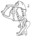
- This may be achieved by relatively moving the frame parts 30, 31 towards one another so that the coupling formations 52, 53 of the second frame part 31 are guided into the channels 35a, 36a of the coupling formations 35, 36 of the first frame part 30, and continuing relatively to move the frame parts 30, 31 until in a registry position in which the openings 58-61 of the second frame part 31 are aligned with the respective openings 63-66 of the first frame part 30.
- the channels 35a, 36a or at least one of them may include internal stops which are engaged by the coupling formations 52, 53 of the second frame part 31 when in the registry position, if desired.
- Figure 4 shows the frame parts 30, 31 in the registry position.
- fasteners such as bolts may be passed into aligned pairs of openings, i.e. 58 and 63, 59 and 64, 60 and 65, 61 and 66.
- the fasteners may be made permanent after tightening so that the coupling of the frame parts 30, 31 is permanent, or may be subsequently releasable to enable the frame parts 31, 31 to be separated during a repair or maintenance procedure, as desired.
- the channels 35a, 36a or other guides could be provided by the coupling formations of the second frame part 31 if desired, or a guide may be provided on each of the frame parts 30, 31.
- the frame parts 30, 31 may be coupled by other means, e.g. by welding the respective coupling formations together, although the use of fasteners is preferred.
- the rear part 34 of the first frame part 30 is of sufficient mass to provide a counterweight to the weight of the working arm 16 when attached and when working.
- the engine 40 and other first frame part machine components will additionally add counterweight as they are positioned rearwardly of the machine 10.
- assembly of the machine 10 may be completed by adding the cab floor 26, and inserting the seat 25, and control lever assembly 24, making hydraulic connections as necessary.
- the hydraulic pump, hydraulic fluid cooler 44, and the hydraulic fluid tank 49 are located by the first frame part 30, it is envisaged that the only hydraulic connections which will need to be made between the machine components of first and second frame parts 30, 31 is a flow from the pump to the control valve assembly, and a return from the control valve assembly to tank 49.
- a single multi-way electrical connector may provide for all electrical connections between the machine components of the first and second frame parts 30, 31 to be made if desired.
- the cab structure 15 may be provided by a frame which provides at least cab sides 71 and a cab roof 72, at least one of the cab sides 71 affording a door opening for a cab door 74, whilst the cab sides are otherwise closed by one or more side panels, and the cab roof is closed by one or more roof panels as seen in figure 1.
- a windscreen may close a front the cab frame, and one or more rear panels may close a cab rear afforded in this example by the cab supporting structure 38, although this may be afforded by the cab frame in another example.
- the cab frame need not include a cab roof or even cab sides or a front, so that the cab merely provides an operator's control position, including a seat 25.
- front 30 and rear 31 frame part configurations shown are only exemplary and many design changes may be made as appropriate for mounting/accommodating the particular machine components for another machine 10 in accordance with the invention.
- the working arm 16 may be mounted on the front frame part 31 prior to or subsequent to coupling the first and second frame parts 30, 31.
- upper frame structure 14 is afforded by only first and second monolithic cast frame parts 30, 31, upper frame structures 14 including more than two frame parts are not precluded from the scope of the invention.
- a bonnet 75 is assembled to the first frame part 30 to close an opening above the rear part 34 and behind the cooling pack 42, and to provide access to the engine 40 and other first frame part machine components, for maintenance purposes.
- the first frame part 30 will always mount the engine 40 and the second frame part 31 the control valve assembly as a minimum, prior to coupling the first and second frame parts 30, 31 together.
- first and second frame parts 30, 31 need not be, respectively, rear and front frame parts, but two frame parts each being a side frame part may be provided, and coupled together by transversely moving together (relative to a longitudinal axis of the machine 10) the frame parts, and coupling them together.
- coupling formations need not include forwardly or rearwardly facing parts, but inwardly sideways extending parts, by means of which the frame parts may be coupled, and preferably connected together by fasteners, welding or any other connecting method.
- the first part may mount the engine at a side of the machine, and the second part, a hydraulic control valve assembly, with each frame part mounting other machine components as requested.
Landscapes
- Engineering & Computer Science (AREA)
- Structural Engineering (AREA)
- Mining & Mineral Resources (AREA)
- Civil Engineering (AREA)
- General Engineering & Computer Science (AREA)
- Mechanical Engineering (AREA)
- Combustion & Propulsion (AREA)
- Transportation (AREA)
- Chemical & Material Sciences (AREA)
- Architecture (AREA)
- Body Structure For Vehicles (AREA)
- Soil Working Implements (AREA)
- Electrical Discharge Machining, Electrochemical Machining, And Combined Machining (AREA)
- Arrangement Or Mounting Of Propulsion Units For Vehicles (AREA)
- Vehicle Cleaning, Maintenance, Repair, Refitting, And Outriggers (AREA)
- Agricultural Machines (AREA)
Applications Claiming Priority (1)
| Application Number | Priority Date | Filing Date | Title |
|---|---|---|---|
| GB0422791A GB2419117B (en) | 2004-10-14 | 2004-10-14 | Working machine |
Related Child Applications (1)
| Application Number | Title | Priority Date | Filing Date |
|---|---|---|---|
| EP11156490.2 Division-Into | 2011-03-01 |
Publications (3)
| Publication Number | Publication Date |
|---|---|
| EP1647635A2 true EP1647635A2 (fr) | 2006-04-19 |
| EP1647635A3 EP1647635A3 (fr) | 2008-07-30 |
| EP1647635B1 EP1647635B1 (fr) | 2011-11-30 |
Family
ID=33462676
Family Applications (1)
| Application Number | Title | Priority Date | Filing Date |
|---|---|---|---|
| EP05021721A Expired - Lifetime EP1647635B1 (fr) | 2004-10-14 | 2005-10-05 | Engin de travaux publics muni d'une tourelle avec un cadre spécial |
Country Status (4)
| Country | Link |
|---|---|
| US (1) | US20060080930A1 (fr) |
| EP (1) | EP1647635B1 (fr) |
| AT (1) | ATE535651T1 (fr) |
| GB (1) | GB2419117B (fr) |
Cited By (3)
| Publication number | Priority date | Publication date | Assignee | Title |
|---|---|---|---|---|
| EP1770223A3 (fr) * | 2005-09-29 | 2007-08-29 | Kobelco Construction Machinery Co., Ltd. | Machine de génie civil |
| EP2177670A1 (fr) * | 2008-10-17 | 2010-04-21 | Liebherr-Hydraulikbagger GmbH | Châssis porteur pour un appareil de travail mobile |
| EP2378008A1 (fr) * | 2010-04-16 | 2011-10-19 | Liebherr-Hydraulikbagger GmbH | Engin ou appareil de transbordement |
Families Citing this family (7)
| Publication number | Priority date | Publication date | Assignee | Title |
|---|---|---|---|---|
| JP4303708B2 (ja) * | 2005-07-05 | 2009-07-29 | ヤンマー株式会社 | 旋回作業車 |
| GB2434344B (en) * | 2006-01-20 | 2009-09-30 | Jcb Compact Products Ltd | Working machine |
| GB2434348A (en) * | 2006-01-20 | 2007-07-25 | Jcb Compact Products Ltd | Track-laying vehicle with cast track sub-frames |
| US8998559B2 (en) * | 2011-09-16 | 2015-04-07 | Deere & Company | Reduced effort manual boom lock |
| NL2008634C2 (nl) * | 2012-04-13 | 2013-10-16 | Hudson Bay Holding B V | Mobiele inrichting. |
| JP6028588B2 (ja) * | 2013-01-22 | 2016-11-16 | コベルコ建機株式会社 | 作業機械 |
| JP6348394B2 (ja) * | 2014-09-30 | 2018-06-27 | 株式会社クボタ | 作業機 |
Citations (3)
| Publication number | Priority date | Publication date | Assignee | Title |
|---|---|---|---|---|
| US1773252A (en) | 1926-01-04 | 1930-08-19 | Bucyrus Erie Co | Excavating machinery |
| JP2003020683A (ja) | 2001-07-09 | 2003-01-24 | Yanmar Co Ltd | 旋回作業車のターニングフレーム |
| EP1306490A1 (fr) | 2000-05-01 | 2003-05-02 | Yanmar Diesel Engine Co. Ltd. | Engin pivotant |
Family Cites Families (13)
| Publication number | Priority date | Publication date | Assignee | Title |
|---|---|---|---|---|
| US2513726A (en) * | 1945-07-05 | 1950-07-04 | William M Huston | Load handling equipment |
| US4124226A (en) * | 1977-10-06 | 1978-11-07 | Harnischfeger Corporation | Electrohydraulic outrigger control system |
| JPH0410290Y2 (fr) * | 1984-11-28 | 1992-03-13 | ||
| US6170588B1 (en) * | 1997-06-03 | 2001-01-09 | Hitachi Construction Machinery Co., Ltd. | Revolving construction machine |
| US6138786A (en) * | 1998-06-05 | 2000-10-31 | Caterpillar S.A.R.L. | Upper frame assembly |
| JP2001040706A (ja) * | 1999-08-03 | 2001-02-13 | Komatsu Ltd | 建設機械の旋回台 |
| US6089343A (en) * | 1999-05-21 | 2000-07-18 | Deere & Company | Vehicle frame |
| JP4113925B2 (ja) * | 2000-01-19 | 2008-07-09 | ヤンマー株式会社 | バックホーのキャビン |
| JP3634723B2 (ja) * | 2000-05-31 | 2005-03-30 | 日立建機株式会社 | 建設機械の旋回フレーム |
| JP2002061224A (ja) * | 2000-08-24 | 2002-02-28 | Hitachi Constr Mach Co Ltd | 旋回式建設機械 |
| JP2002097666A (ja) * | 2000-09-27 | 2002-04-02 | Komatsu Ltd | 建設機械の旋回フレーム |
| JP2003082705A (ja) * | 2001-09-10 | 2003-03-19 | Hitachi Constr Mach Co Ltd | 建設機械の旋回フレームおよびその製造方法 |
| US7004275B1 (en) * | 2004-08-13 | 2006-02-28 | Ingersoll-Rand Company | Movable operator station for vehicles |
-
2004
- 2004-10-14 GB GB0422791A patent/GB2419117B/en not_active Expired - Fee Related
-
2005
- 2005-10-05 EP EP05021721A patent/EP1647635B1/fr not_active Expired - Lifetime
- 2005-10-05 AT AT05021721T patent/ATE535651T1/de active
- 2005-10-11 US US11/247,502 patent/US20060080930A1/en not_active Abandoned
Patent Citations (3)
| Publication number | Priority date | Publication date | Assignee | Title |
|---|---|---|---|---|
| US1773252A (en) | 1926-01-04 | 1930-08-19 | Bucyrus Erie Co | Excavating machinery |
| EP1306490A1 (fr) | 2000-05-01 | 2003-05-02 | Yanmar Diesel Engine Co. Ltd. | Engin pivotant |
| JP2003020683A (ja) | 2001-07-09 | 2003-01-24 | Yanmar Co Ltd | 旋回作業車のターニングフレーム |
Cited By (9)
| Publication number | Priority date | Publication date | Assignee | Title |
|---|---|---|---|---|
| EP1770223A3 (fr) * | 2005-09-29 | 2007-08-29 | Kobelco Construction Machinery Co., Ltd. | Machine de génie civil |
| US7810597B2 (en) | 2005-09-29 | 2010-10-12 | Kobelco Construction Machinery Co., Ltd. | Battery placement and support on the body frame of a construction machine |
| EP2177670A1 (fr) * | 2008-10-17 | 2010-04-21 | Liebherr-Hydraulikbagger GmbH | Châssis porteur pour un appareil de travail mobile |
| US8177017B2 (en) | 2008-10-17 | 2012-05-15 | Liebherr-Hydraulikbagger Gmbh | Traveling working machine |
| EP2573280A3 (fr) * | 2008-10-17 | 2014-05-14 | Liebherr-Hydraulikbagger GmbH | Structure en acier supportant la superstructure d'un engin de travail |
| EP2378008A1 (fr) * | 2010-04-16 | 2011-10-19 | Liebherr-Hydraulikbagger GmbH | Engin ou appareil de transbordement |
| DE102010015163A1 (de) * | 2010-04-16 | 2011-10-20 | Liebherr-Hydraulikbagger Gmbh | Baumaschine oder Umschlaggerät |
| CN102251544A (zh) * | 2010-04-16 | 2011-11-23 | 利勃海尔液压挖掘机有限公司 | 工程机器或传输设备 |
| US8657057B2 (en) | 2010-04-16 | 2014-02-25 | Liebherr-Hydraulikbagger Gmbh | Construction machine or transfer apparatus |
Also Published As
| Publication number | Publication date |
|---|---|
| EP1647635A3 (fr) | 2008-07-30 |
| US20060080930A1 (en) | 2006-04-20 |
| ATE535651T1 (de) | 2011-12-15 |
| EP1647635B1 (fr) | 2011-11-30 |
| GB2419117B (en) | 2008-03-05 |
| GB0422791D0 (en) | 2004-11-17 |
| GB2419117A (en) | 2006-04-19 |
Similar Documents
| Publication | Publication Date | Title |
|---|---|---|
| US7481289B2 (en) | Swiveling work machine | |
| EP2778294B1 (fr) | Équipement de construction | |
| EP1647635B1 (fr) | Engin de travaux publics muni d'une tourelle avec un cadre spécial | |
| US12345016B2 (en) | Construction machine | |
| KR20100085820A (ko) | 건설 기계 | |
| JP6600583B2 (ja) | 建設機械および建設機械のエンジンカバー取付方法 | |
| US9650757B2 (en) | Construction machine | |
| JP4882098B2 (ja) | 掘削作業車 | |
| JP3691750B2 (ja) | 旋回作業機 | |
| JP4199173B2 (ja) | 旋回式建設機械 | |
| JP2007170129A (ja) | 建設機械 | |
| JP4478782B2 (ja) | 掘削作業車 | |
| JP2024011409A (ja) | 建設機械 | |
| JP6961635B2 (ja) | 建設機械 | |
| JP4885787B2 (ja) | 建設機械 | |
| EP4365370A1 (fr) | Structure de serrage de tuyau flexible et engin de chantier | |
| JP4061063B2 (ja) | 建設機械 | |
| JP6479646B2 (ja) | 小型の建設機械 | |
| JP6712671B2 (ja) | 分解型作業機械 | |
| JP4266765B2 (ja) | 旋回作業機 | |
| EP4506511A1 (fr) | Engin de chantier | |
| EP4424923A1 (fr) | Engin de chantier | |
| JP2026053933A (ja) | 作業機械 | |
| JP2005002573A (ja) | 掘削作業車 | |
| JP2019135370A (ja) | 建設機械 |
Legal Events
| Date | Code | Title | Description |
|---|---|---|---|
| PUAI | Public reference made under article 153(3) epc to a published international application that has entered the european phase |
Free format text: ORIGINAL CODE: 0009012 |
|
| AK | Designated contracting states |
Kind code of ref document: A2 Designated state(s): AT BE BG CH CY CZ DE DK EE ES FI FR GB GR HU IE IS IT LI LT LU LV MC NL PL PT RO SE SI SK TR |
|
| AX | Request for extension of the european patent |
Extension state: AL BA HR MK YU |
|
| RIC1 | Information provided on ipc code assigned before grant |
Ipc: E02F 9/12 20060101AFI20060120BHEP Ipc: B62D 25/00 20060101ALI20080407BHEP |
|
| PUAL | Search report despatched |
Free format text: ORIGINAL CODE: 0009013 |
|
| AK | Designated contracting states |
Kind code of ref document: A3 Designated state(s): AT BE BG CH CY CZ DE DK EE ES FI FR GB GR HU IE IS IT LI LT LU LV MC NL PL PT RO SE SI SK TR |
|
| AX | Request for extension of the european patent |
Extension state: AL BA HR MK YU |
|
| 17P | Request for examination filed |
Effective date: 20090116 |
|
| 17Q | First examination report despatched |
Effective date: 20090219 |
|
| R17C | First examination report despatched (corrected) |
Effective date: 20090302 |
|
| AKX | Designation fees paid |
Designated state(s): AT BE BG CH CY CZ DE DK EE ES FI FR GB GR HU IE IS IT LI LT LU LV MC NL PL PT RO SE SI SK TR |
|
| GRAP | Despatch of communication of intention to grant a patent |
Free format text: ORIGINAL CODE: EPIDOSNIGR1 |
|
| GRAS | Grant fee paid |
Free format text: ORIGINAL CODE: EPIDOSNIGR3 |
|
| GRAA | (expected) grant |
Free format text: ORIGINAL CODE: 0009210 |
|
| AK | Designated contracting states |
Kind code of ref document: B1 Designated state(s): AT BE BG CH CY CZ DE DK EE ES FI FR GB GR HU IE IS IT LI LT LU LV MC NL PL PT RO SE SI SK TR |
|
| REG | Reference to a national code |
Ref country code: CH Ref legal event code: EP Ref country code: GB Ref legal event code: FG4D |
|
| REG | Reference to a national code |
Ref country code: IE Ref legal event code: FG4D |
|
| REG | Reference to a national code |
Ref country code: DE Ref legal event code: R096 Ref document number: 602005031432 Country of ref document: DE Effective date: 20120126 |
|
| REG | Reference to a national code |
Ref country code: NL Ref legal event code: VDEP Effective date: 20111130 |
|
| REG | Reference to a national code |
Ref country code: SE Ref legal event code: TRGR |
|
| LTIE | Lt: invalidation of european patent or patent extension |
Effective date: 20111130 |
|
| PG25 | Lapsed in a contracting state [announced via postgrant information from national office to epo] |
Ref country code: IS Free format text: LAPSE BECAUSE OF FAILURE TO SUBMIT A TRANSLATION OF THE DESCRIPTION OR TO PAY THE FEE WITHIN THE PRESCRIBED TIME-LIMIT Effective date: 20120330 Ref country code: LT Free format text: LAPSE BECAUSE OF FAILURE TO SUBMIT A TRANSLATION OF THE DESCRIPTION OR TO PAY THE FEE WITHIN THE PRESCRIBED TIME-LIMIT Effective date: 20111130 |
|
| PG25 | Lapsed in a contracting state [announced via postgrant information from national office to epo] |
Ref country code: LV Free format text: LAPSE BECAUSE OF FAILURE TO SUBMIT A TRANSLATION OF THE DESCRIPTION OR TO PAY THE FEE WITHIN THE PRESCRIBED TIME-LIMIT Effective date: 20111130 Ref country code: NL Free format text: LAPSE BECAUSE OF FAILURE TO SUBMIT A TRANSLATION OF THE DESCRIPTION OR TO PAY THE FEE WITHIN THE PRESCRIBED TIME-LIMIT Effective date: 20111130 Ref country code: GR Free format text: LAPSE BECAUSE OF FAILURE TO SUBMIT A TRANSLATION OF THE DESCRIPTION OR TO PAY THE FEE WITHIN THE PRESCRIBED TIME-LIMIT Effective date: 20120301 Ref country code: SI Free format text: LAPSE BECAUSE OF FAILURE TO SUBMIT A TRANSLATION OF THE DESCRIPTION OR TO PAY THE FEE WITHIN THE PRESCRIBED TIME-LIMIT Effective date: 20111130 Ref country code: BE Free format text: LAPSE BECAUSE OF FAILURE TO SUBMIT A TRANSLATION OF THE DESCRIPTION OR TO PAY THE FEE WITHIN THE PRESCRIBED TIME-LIMIT Effective date: 20111130 Ref country code: PT Free format text: LAPSE BECAUSE OF FAILURE TO SUBMIT A TRANSLATION OF THE DESCRIPTION OR TO PAY THE FEE WITHIN THE PRESCRIBED TIME-LIMIT Effective date: 20120330 |
|
| PG25 | Lapsed in a contracting state [announced via postgrant information from national office to epo] |
Ref country code: CY Free format text: LAPSE BECAUSE OF FAILURE TO SUBMIT A TRANSLATION OF THE DESCRIPTION OR TO PAY THE FEE WITHIN THE PRESCRIBED TIME-LIMIT Effective date: 20111130 |
|
| PG25 | Lapsed in a contracting state [announced via postgrant information from national office to epo] |
Ref country code: EE Free format text: LAPSE BECAUSE OF FAILURE TO SUBMIT A TRANSLATION OF THE DESCRIPTION OR TO PAY THE FEE WITHIN THE PRESCRIBED TIME-LIMIT Effective date: 20111130 Ref country code: DK Free format text: LAPSE BECAUSE OF FAILURE TO SUBMIT A TRANSLATION OF THE DESCRIPTION OR TO PAY THE FEE WITHIN THE PRESCRIBED TIME-LIMIT Effective date: 20111130 Ref country code: BG Free format text: LAPSE BECAUSE OF FAILURE TO SUBMIT A TRANSLATION OF THE DESCRIPTION OR TO PAY THE FEE WITHIN THE PRESCRIBED TIME-LIMIT Effective date: 20120229 Ref country code: SK Free format text: LAPSE BECAUSE OF FAILURE TO SUBMIT A TRANSLATION OF THE DESCRIPTION OR TO PAY THE FEE WITHIN THE PRESCRIBED TIME-LIMIT Effective date: 20111130 Ref country code: CZ Free format text: LAPSE BECAUSE OF FAILURE TO SUBMIT A TRANSLATION OF THE DESCRIPTION OR TO PAY THE FEE WITHIN THE PRESCRIBED TIME-LIMIT Effective date: 20111130 |
|
| PG25 | Lapsed in a contracting state [announced via postgrant information from national office to epo] |
Ref country code: RO Free format text: LAPSE BECAUSE OF FAILURE TO SUBMIT A TRANSLATION OF THE DESCRIPTION OR TO PAY THE FEE WITHIN THE PRESCRIBED TIME-LIMIT Effective date: 20111130 Ref country code: PL Free format text: LAPSE BECAUSE OF FAILURE TO SUBMIT A TRANSLATION OF THE DESCRIPTION OR TO PAY THE FEE WITHIN THE PRESCRIBED TIME-LIMIT Effective date: 20111130 |
|
| REG | Reference to a national code |
Ref country code: AT Ref legal event code: MK05 Ref document number: 535651 Country of ref document: AT Kind code of ref document: T Effective date: 20111130 |
|
| PLBE | No opposition filed within time limit |
Free format text: ORIGINAL CODE: 0009261 |
|
| STAA | Information on the status of an ep patent application or granted ep patent |
Free format text: STATUS: NO OPPOSITION FILED WITHIN TIME LIMIT |
|
| 26N | No opposition filed |
Effective date: 20120831 |
|
| REG | Reference to a national code |
Ref country code: DE Ref legal event code: R097 Ref document number: 602005031432 Country of ref document: DE Effective date: 20120831 |
|
| PG25 | Lapsed in a contracting state [announced via postgrant information from national office to epo] |
Ref country code: AT Free format text: LAPSE BECAUSE OF FAILURE TO SUBMIT A TRANSLATION OF THE DESCRIPTION OR TO PAY THE FEE WITHIN THE PRESCRIBED TIME-LIMIT Effective date: 20111130 |
|
| PG25 | Lapsed in a contracting state [announced via postgrant information from national office to epo] |
Ref country code: ES Free format text: LAPSE BECAUSE OF FAILURE TO SUBMIT A TRANSLATION OF THE DESCRIPTION OR TO PAY THE FEE WITHIN THE PRESCRIBED TIME-LIMIT Effective date: 20120311 |
|
| PG25 | Lapsed in a contracting state [announced via postgrant information from national office to epo] |
Ref country code: MC Free format text: LAPSE BECAUSE OF NON-PAYMENT OF DUE FEES Effective date: 20121031 |
|
| REG | Reference to a national code |
Ref country code: CH Ref legal event code: PL |
|
| PG25 | Lapsed in a contracting state [announced via postgrant information from national office to epo] |
Ref country code: FI Free format text: LAPSE BECAUSE OF FAILURE TO SUBMIT A TRANSLATION OF THE DESCRIPTION OR TO PAY THE FEE WITHIN THE PRESCRIBED TIME-LIMIT Effective date: 20111130 |
|
| REG | Reference to a national code |
Ref country code: IE Ref legal event code: MM4A |
|
| PG25 | Lapsed in a contracting state [announced via postgrant information from national office to epo] |
Ref country code: IE Free format text: LAPSE BECAUSE OF NON-PAYMENT OF DUE FEES Effective date: 20121005 Ref country code: CH Free format text: LAPSE BECAUSE OF NON-PAYMENT OF DUE FEES Effective date: 20121031 Ref country code: LI Free format text: LAPSE BECAUSE OF NON-PAYMENT OF DUE FEES Effective date: 20121031 |
|
| PG25 | Lapsed in a contracting state [announced via postgrant information from national office to epo] |
Ref country code: TR Free format text: LAPSE BECAUSE OF FAILURE TO SUBMIT A TRANSLATION OF THE DESCRIPTION OR TO PAY THE FEE WITHIN THE PRESCRIBED TIME-LIMIT Effective date: 20111130 |
|
| PG25 | Lapsed in a contracting state [announced via postgrant information from national office to epo] |
Ref country code: LU Free format text: LAPSE BECAUSE OF NON-PAYMENT OF DUE FEES Effective date: 20121005 |
|
| PG25 | Lapsed in a contracting state [announced via postgrant information from national office to epo] |
Ref country code: HU Free format text: LAPSE BECAUSE OF FAILURE TO SUBMIT A TRANSLATION OF THE DESCRIPTION OR TO PAY THE FEE WITHIN THE PRESCRIBED TIME-LIMIT Effective date: 20051005 |
|
| REG | Reference to a national code |
Ref country code: FR Ref legal event code: PLFP Year of fee payment: 11 |
|
| REG | Reference to a national code |
Ref country code: FR Ref legal event code: PLFP Year of fee payment: 12 |
|
| REG | Reference to a national code |
Ref country code: FR Ref legal event code: PLFP Year of fee payment: 13 |
|
| REG | Reference to a national code |
Ref country code: FR Ref legal event code: PLFP Year of fee payment: 14 |
|
| PGFP | Annual fee paid to national office [announced via postgrant information from national office to epo] |
Ref country code: SE Payment date: 20211020 Year of fee payment: 17 |
|
| PGFP | Annual fee paid to national office [announced via postgrant information from national office to epo] |
Ref country code: FR Payment date: 20221028 Year of fee payment: 18 |
|
| PGFP | Annual fee paid to national office [announced via postgrant information from national office to epo] |
Ref country code: IT Payment date: 20221021 Year of fee payment: 18 Ref country code: DE Payment date: 20221019 Year of fee payment: 18 |
|
| REG | Reference to a national code |
Ref country code: SE Ref legal event code: EUG |
|
| PG25 | Lapsed in a contracting state [announced via postgrant information from national office to epo] |
Ref country code: SE Free format text: LAPSE BECAUSE OF NON-PAYMENT OF DUE FEES Effective date: 20221006 |
|
| REG | Reference to a national code |
Ref country code: DE Ref legal event code: R119 Ref document number: 602005031432 Country of ref document: DE |
|
| PG25 | Lapsed in a contracting state [announced via postgrant information from national office to epo] |
Ref country code: FR Free format text: LAPSE BECAUSE OF NON-PAYMENT OF DUE FEES Effective date: 20231031 Ref country code: DE Free format text: LAPSE BECAUSE OF NON-PAYMENT OF DUE FEES Effective date: 20240501 |
|
| P01 | Opt-out of the competence of the unified patent court (upc) registered |
Free format text: CASE NUMBER: UPC_APP_427132/2023 Effective date: 20230525 |
|
| PG25 | Lapsed in a contracting state [announced via postgrant information from national office to epo] |
Ref country code: IT Free format text: LAPSE BECAUSE OF NON-PAYMENT OF DUE FEES Effective date: 20231005 |
|
| PG25 | Lapsed in a contracting state [announced via postgrant information from national office to epo] |
Ref country code: IT Free format text: LAPSE BECAUSE OF NON-PAYMENT OF DUE FEES Effective date: 20231005 |
|
| PGFP | Annual fee paid to national office [announced via postgrant information from national office to epo] |
Ref country code: GB Payment date: 20241018 Year of fee payment: 20 |
|
| REG | Reference to a national code |
Ref country code: GB Ref legal event code: PE20 Expiry date: 20251004 |