EP1647639A2 - Fernbedienung - Google Patents
Fernbedienung Download PDFInfo
- Publication number
- EP1647639A2 EP1647639A2 EP05019762A EP05019762A EP1647639A2 EP 1647639 A2 EP1647639 A2 EP 1647639A2 EP 05019762 A EP05019762 A EP 05019762A EP 05019762 A EP05019762 A EP 05019762A EP 1647639 A2 EP1647639 A2 EP 1647639A2
- Authority
- EP
- European Patent Office
- Prior art keywords
- cap
- tiltable member
- remote controller
- pressed
- main body
- Prior art date
- Legal status (The legal status is an assumption and is not a legal conclusion. Google has not performed a legal analysis and makes no representation as to the accuracy of the status listed.)
- Granted
Links
Images


Classifications
-
- E—FIXED CONSTRUCTIONS
- E03—WATER SUPPLY; SEWERAGE
- E03C—DOMESTIC PLUMBING INSTALLATIONS FOR FRESH WATER OR WASTE WATER; SINKS
- E03C1/00—Domestic plumbing installations for fresh water or waste water; Sinks
- E03C1/02—Plumbing installations for fresh water
- E03C1/05—Arrangements of devices on wash-basins, baths, sinks, or the like for remote control of taps
- E03C1/055—Electrical control devices, e.g. with push buttons, control panels or the like
-
- E—FIXED CONSTRUCTIONS
- E03—WATER SUPPLY; SEWERAGE
- E03D—WATER-CLOSETS OR URINALS WITH FLUSHING DEVICES; FLUSHING VALVES THEREFOR
- E03D5/00—Special constructions of flushing devices, e.g. closed flushing system
- E03D5/10—Special constructions of flushing devices, e.g. closed flushing system operated electrically, e.g. by a photo-cell; also combined with devices for opening or closing shutters in the bowl outlet and/or with devices for raising/or lowering seat and cover and/or for swiveling the bowl
- E03D5/105—Special constructions of flushing devices, e.g. closed flushing system operated electrically, e.g. by a photo-cell; also combined with devices for opening or closing shutters in the bowl outlet and/or with devices for raising/or lowering seat and cover and/or for swiveling the bowl touchless, e.g. using sensors
-
- H—ELECTRICITY
- H01—ELECTRIC ELEMENTS
- H01H—ELECTRIC SWITCHES; RELAYS; SELECTORS; EMERGENCY PROTECTIVE DEVICES
- H01H2221/00—Actuators
- H01H2221/088—Actuators actuable from different directions
-
- H—ELECTRICITY
- H01—ELECTRIC ELEMENTS
- H01H—ELECTRIC SWITCHES; RELAYS; SELECTORS; EMERGENCY PROTECTIVE DEVICES
- H01H9/00—Details of switching devices, not covered by groups H01H1/00 - H01H7/00
- H01H9/02—Bases, casings, or covers
- H01H9/0214—Hand-held casings
- H01H9/0235—Hand-held casings specially adapted for remote control, e.g. of audio or video apparatus
-
- H—ELECTRICITY
- H03—ELECTRONIC CIRCUITRY
- H03K—PULSE TECHNIQUE
- H03K17/00—Electronic switching or gating, i.e. not by contact-making and –breaking
- H03K17/94—Electronic switching or gating, i.e. not by contact-making and –breaking characterised by the way in which the control signals are generated
- H03K17/965—Switches controlled by moving an element forming part of the switch
Definitions
- the present invention relates to a remote controller attached to a wall of a lavatory or the like.
- Toilet equipment which permits the user to control the toilet equipment, for example, to flush a toilet bowl with flushing water after use by operating a switch on a remote controller is widely prevalent.
- Such remote controller is usually located at a relatively lower position for the purpose of permitting the user to easily operate even when the user is seated on the toilet seat. Consequently, particularly in the case of a tall user, the user may have a difficulty in operating switches on the remote controller in his or her standing state.
- JP 2002-70115A publication discloses a remote controller having a button as a switch to be operated, which is arranged to lie astride the top surface and the front surface of the remote controller. As shown in Fig. 5 of the '115 publication, an upper rear portion of the button is supported pivotally by a pivot pin. Accordingly, when the user presses the upper rear portion of the button, switching operation is not achieved because the button does not move downward. That is, the switching operation is not achieved unless the user presses an upper front portion of the button when the user operates from above.
- a remote controller of the present invention has a main body to be attached to a wall; at least one tiltable member which is arranged on an upper portion of the main body and is supported to the main body such that the tiltable member tilts even when it is pressed from any direction between front and above; and at least one switch body which is pressed when the tiltable member tilts.
- the tiltable member is tiltably supported at its front lower side to the main body.
- switching operation is achieved by pressing the tiltable member from any direction between front and above so as to make the tiltable member tilt.
- the tiltable member is tiltably supported at its front lower side to the main body. Therefore, even when a user presses any portion on the top of the tiltable member, for example, even when the user presses the upper rear portion, the tiltable member tilts so as to achieve the switching operation.
- a cap may be attached to the top of the remote controller such that the cap is movable in the anteroposterior direction and the vertical direction. In this case, when the cap is pressed from any direction between front and above, the tiltable member is presses by the cap so as to tilt.
- the cap is formed to have a shape fitting the contour of the main body, thereby improving the design of the remote controller.
- the cap may be provided with a cavity which is concaved upward from the bottom.
- the tiltable member is disposed inside the cavity, thereby keeping the volume of an assembly of the cap and the tiltable member to be relatively small.
- the outer surface of the cap from the front side to the rear side via the top may be curved into an upward convex shape so that the user can easily touch the cap with his or her finger tip in either direction, i.e., from front or from above.
- the cap having this shape is hard to be pulled up by taking it between fingers, so that the cap is hardly tampered to be removed from the main body. Even if the space between the cap and the wall to which the remote controller is attached is very small, the cap tilts backward not to collide with the wall when the cap is pressed from front.
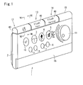
- Fig. 1 is a perspective view of a remote controller according to the embodiment
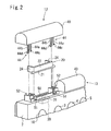
- Fig. 2 is an exploded perspective view of a switch of the remote controller
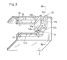
- Fig. 3 is a sectional perspective view of an upper portion of a main body in a state that a cap and a tiltable member are removed
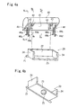
- Fig. 4a is an exploded perspective view of the cap and the tiltable member as seen from the opposite side as seen in Fig. 2
- Fig. 4b is a perspective view of the bottom of the tiltable member
- Figs. 5a, 5b, and 5c are sectional views taken along a line Va-Va of Fig. 4a, a line Vb-Vb of Fig. 4a, and a line Vc-Vc of Fig.
- Fig. 6a is a sectional view taken along a line VI-VI of Fig. 1
- Figs. 6b and 6c are sectional views of the same portion as shown in Fig. 6a in a state that the cap is pressed from front and in a state that the cap is pressed from above, respectively.
- Fig. 7a is a sectional view taken along a line VII-VII of Fig. 1 and Fig. 3, and Figs. 7b and 7c are sectional views of the same portion as shown in Fig. 7a in a state that the cap is pressed from front and in a state that the cap is pressed from above, respectively.
- the remote controller 1 permits the user to remotely control a warm-water cleansing device, a flushing device, and a motorized toilet seat open/close device which are provided on a western-style toilet in a lavatory.
- the warm-water cleansing device comprises a shower nozzle for cleansing the bottom of a user seated on the toilet seat, a bidet nozzle, a warm water tank for supplying warm water to the nozzles, a warm-air dryer for drying the bottom by blowing warm air to the bottom, and the like.
- the flushing device has a valve unit for supplying flushing water to the toilet bowl.
- the motorized toilet seat open/close device raises or lays down the toilet seat by a motor.
- the remote controller 1 has a main body 2 to be attached to a wall of the lavatory, front switches 3 through 10 and a dial 11 which are provided on the front surface of the main body 2, switches 12 through 14 and a transmitter portion 15 for sending commands from the respective switches and the dial to the respective devices, which are provided on the top of the main body,
- the upper surface of the main body 2 is separated substantially equally into four regions in the lateral direction. At these regions, in the order from the left, a toilet seat open/close switch 12, a full flushing switch 13, a partial flushing switch 14, and the transmitter portion 15 are arranged, respectively.
- the arrangement of the switches 12 through 14 is not limited thereto.
- the front switches 3 through 10 are a bottom cleansing switch 3, a bidet switch 4, a drying switch 5, a forward switch 6 and a backward switch 7 for adjusting the nozzle position, a wide range ON/OFF switch 8, a massage ON/OFF switch 9, and a stop switch 10 for stopping the cleansing action or the drying action.
- the dial 11 is for adjusting the strength of water jet from each nozzle.
- the nozzle As the frontward switch 6 is pressed during the bottom cleansing or bidet cleansing, the nozzle is moved forward so that the cleansing position shifts forward. As the backward switch 7 is pressed, the nozzle is moved backward so that the cleansing position shifts backward. As the wide range ON/OFF switch 8 is pressed once to set the wide-range cleansing function, the nozzle automatically repeatedly moves to and fro so as to cleanse a wider range during the bottom or bidet cleansing. As the wide range ON/OFF switch 8 is pressed once again, the wide-range cleansing function is cancelled.
- the strength of water jet is varied to get stronger and weaker alternately to conduct massage during the bottom or bidet cleansing.
- the massage ON/OFF switch 9 is pressed once again, the massage function is cancelled.
- the strength of water jet during the bottom or bidet cleansing is normally adjusted by turning the dial 11 clockwise or counter clockwise.
- the drying switch 5 As the drying switch 5 is pressed once, relatively high temperature warm air is blown out. As it is pressed once again, the warm air is changed to medium temperature warm air. Further, as it is pressed again, the warm air is changed to relatively low temperature warm air. After that, the warm air is changed in the same manner, i.e. high-medium-low manner. As the stop switch 10 is pressed, the aforementioned cleansing action or the drying (warm air blowing) action is stopped. In this embodiment, self-stopping mechanism is employed to automatically stop the cleansing after two minutes from the start and to automatically stop the drying after four minutes from the start.
- the main body 2 is provided at its front lower surface with a front lid 16.
- the front lid 16 is allowed to be opened forward or closed by a hinge (not shown).
- auxiliary control switches such as a water temperature adjusting switch and a seat temperature adjusting switch are provided.
- the motor is actuated to raise the toilet seat.
- the motor is actuated reversely to lay down the toilet seat onto the toilet bowl.
- the full flushing switch 13 is pressed, a large quantity of washing water is supplied to a basin portion of the toilet bowl.
- the portion flushing switch 14 is pressed, a small quantity of washing water is supplied to the basin portion of the toilet bowl.
- the toilet seat open/close switch 12 has a tiltable member 20 which is tiltably supported at its front lower portion to an upper portion of the main body 2 so that the tiltable member 20 can tilt even when it is pressed from any direction between front and above, as shown in Figs. 6a-6c, a switch body 30 which is pressed by the tiltable member 20 when the tiltable member 20 tilts so as to conduct switching action, and a cap 40 which is mounted to the upper portion of the main body 2 such that the cap 40 can be freely displaced in the anteroposterior direction and the vertical direction.
- each switch body 30 has an actuator 31 which retracts when pressed to conduct the switching action.
- the actuator 31 is arranged to face upward the opening 50.
- bearing portions 51,51 for holding a rotary shaft 21 of the tiltable member 20 as will be described later are formed.
- leg receiving portions 52, 52 for receiving legs 44, 44 of the cap 40 as will be described later are formed, respectively.
- the tiltable member 20 has the rotary shaft 21 extending in the lateral direction of the main body 2, a vertical piece 22 extending upward from the rotary shaft 21, a horizontal piece 23 extending backward from the rotary shaft 21 at right angle to the vertical piece 22, rib pieces 24, 24 connecting the left ends of and the right ends of the vertical piece 22 and the horizontal piece 23, respectively, and a convex portion 25 projecting downward from the bottom of the horizontal piece 23.
- the shaft 21 is disposed along the front edge of the opening 50 such that the both ends of the shaft 21 are held by the bearing portions 51, 51.
- the horizontal piece 23 extends inside of the opening 50 to cover the upper side of the switch body 30.
- the convex portion 25 on the bottom of the horizontal piece 23 faces the upper end of the actuator 31 of the switch body 30.
- the convex portion 25 is made of a relatively flexible synthetic resin or rubber.
- the cap 40 has a semi-cylinder shape of which outer surface from the front side to the rear side via the top is curved into an upward convex shape.
- the cap 40 has a cavity 41 which is concaved upward from the bottom.
- the tiltable member 20 and the bearing portions 51, 51 and the receiving portions 52, 52 around the opening 50 are accommodated inside the cavity 41.
- backward pressing pieces 42 facing the front of the vertical piece 22 and downward pressing pieces 43 facing the upper surface of the horizontal piece 23 are formed to project from the inner surface of the cavity 41.
- the backward pressing piece 42 and the downward pressing piece 43 are formed integrally as a partition extending across the cavity 41 in an anteroposterior direction. Between the backward pressing piece 42 and the downward pressing piece 43, a concavity (without reference numeral) cut away from the lower edge of the partition is formed. The vertical piece 22 enters the concavity.
- Legs 44, 44 are suspended downward from a left end portion and a right end portion of the ceiling of the cavity 41.
- the legs 44, 44 extend downward over the bottom of the cap 40.
- Each leg 44 is branched into a front piece 44a and a rear piece 44b from the middle in the downward direction.
- the rear piece 44b extends downward longer than the front piece 44a.
- the front piece 44a and the rear piece 44b are elastically deformable in the direction of moving apart from and closer to each other.
- the front piece 44a and the rear piece 44b are provided at their lower ends with pawls 44c, 44d which project in a direction apart from each other.
- the legs 44, 44 are received with the aforementioned receiving portions 52, 52 in such a manner as to allow the displacement of the legs 44, 44 in the vertical and anteroposterior directions.
- each receiving portion 52 has a side wall 52a projecting upward from a side edge of the opening 50, a facing wall 52b which is formed at an inner side of the opening 50 to face the side wall 52a with a distance from the side wall 52a, a front-side wall 52c connecting the front side edges of the side wall 52a and the facing wall 52b, a leg passage 52d surrounded by the side wall 52a, the facing wall 52b, and the front-side wall 52c, and a front piece engaging portion 52e and a rear piece engaging portion 52f (only shown in Figs. 7a-7c) formed at a lower side of the passage 52d.
- the legs 44 are inserted from above into the leg passages 52d of the receiving portions 52, respectively.
- the front piece 44a and the rear piece 44b of the leg 44 are elastically deformed to pass between the front piece engaging portion 52e and the rear piece engaging portion 52f so that the pawls 44c, 44d at the lower ends thereof are engaged with the lower ends of the engaging portions 52e, 52f.
- the cap 40 As the cap 40 is pressed from front in the state shown in Fig. 7a, the cap 40 tilts backward as shown in Fig. 7b, the backward pressing piece 42 presses the vertical piece 22 backward to tilt the tiltable member 20.
- the cap 40 As the cap 40 is pressed from above in the state shown in Fig. 7a, the cap 40 lowers as shown in Fig. 7c so that the downward pressing piece 43 presses downward the horizontal piece 23, thereby tilting the tiltable member 20.
- the actuator 31 By the tilting of the tiltable member 20, the actuator 31 is pressed downward via the convex portion 25.
- the periphery of the opening 50 is formed with a convexly stepped portion 53 higher than the surrounding portion.
- the convexly stepped portion 53 is structured to come in contact with the inner wall of the cavity 41 or the lower edge of the downward pressing piece 43 as shown in Figs. 6b and 6c, thereby preventing further displacement of the cap 40.
- a concavely stepped portion 52g is formed in the front side wall 52c of the receiving portion 52 from the middle in the width direction of the opening 50 such that the concavely stepped portion 52g retracts toward the rear of the main body 2.
- the end of the rotary shaft 21 is disposed at a lower end of the concavely stepped portion 52g.
- a confronting piece 51a which confronts the rotary shaft 21 from the front side is formed, thereby holding the end of the rotary shaft 21 in the concavely stepped portion 52g.
- an elastic projection 52h is formed on the middle of the concavely stepped portion 52g in the vertical direction for preventing the end of the rotary shaft 21 from coming off the lower end of the concavely stepped portion 52g. That is, in this embodiment, the bearing portion 51 is composed of the concavely stepped portion 52, the confronting piece 51a, and the elastic projection 52h.
- the end of the rotary shaft 21 is fallen from above along the concavely stepped portion 52g and is pressed into the lower end of the concavely stepped portion 52g through between the elastic projection 52h and the confronting piece 51a.
- the cap 40 of the switch is pressed from front or from above. Accordingly, the tiltable member 20 tilts and the actuator 31 is pressed downward, whereby the switch body 30 conducts the switching action.
- the tiltable member 20 is tiltably supported at its front lower portion to the main body 2 via the rotary shaft 21 so that the tiltable member 20 can tilts. Therefore, the tiltable member 20 is tilted, even when the user presses the cap 40 from any direction between front and above, at its any portion except for the front lowest portion thereof, thereby conducting the switching action.
- the cap 40 is mounted to the tiltable member 20.
- the cap 40 may be formed to have a shape fitting the contour of the main body 2, thereby improving the design of the remote controller.
- the tiltable member 20 is arranged inside the cap 40. Therefore, even when the cap 40 is formed to have wide surface for facilitating the operation, the volume of an assembly of the cap 40 and the tiltable member 20 can be relatively small.
- the outer surface from the front side to the rear side via the top of the cap 40 is curved into an upward convex shape, the user can easily touch the cap 40 with his or her finger tip in either direction, i.e., from front or from above.
- the cap 40 having this shape is hard to be pulled up between fingers, so that the cap 40 is hardly tampered to be removed from the main body 2. It should be noted that even when the space between the cap 40 and the wall to which the remote controller is attached is very small, the cap 40 tilts backward not to collide with the wall when the cap 40 is pressed from front.
- the switch body 30 since the amount of displacement of the cap 40 in the backward direction and the downward direction is restricted, the switch body 30 is prevented from being applied with excess load even when the cap 40 is strongly pressed.
- the aforementioned embodiment is one of examples of the present invention so that the present invention is not limited to the aforementioned embodiment.
- the cap may have another shape, not the illustrated shape.
- some or all of the switches 12, 13, 14 may be provided, in their upper surfaces, with concavities and/or convexities.
- the concavities and/or convexities formed in the upper surfaces of the respective switches may be different in the size, the array arrangement, and/or the configuration, thereby allowing the user to distinguish each switch by the touch of his or her finger.
- One of the switches may be provided with no convexities and the other switches may be provided with convexities, thereby providing different touch to the one switch from the other switches.
- Examples of the convexities include dot-like projections and ridges extending in the lateral direction, while examples of the concavities include dents and grooves extending in the lateral direction.
Landscapes
- Engineering & Computer Science (AREA)
- Health & Medical Sciences (AREA)
- Life Sciences & Earth Sciences (AREA)
- Hydrology & Water Resources (AREA)
- Public Health (AREA)
- Water Supply & Treatment (AREA)
- Aviation & Aerospace Engineering (AREA)
- Selective Calling Equipment (AREA)
- Bidet-Like Cleaning Device And Other Flush Toilet Accessories (AREA)
- Switches With Compound Operations (AREA)
Applications Claiming Priority (1)
| Application Number | Priority Date | Filing Date | Title |
|---|---|---|---|
| JP2004299029A JP4552589B2 (ja) | 2004-10-13 | 2004-10-13 | リモコン |
Publications (3)
| Publication Number | Publication Date |
|---|---|
| EP1647639A2 true EP1647639A2 (de) | 2006-04-19 |
| EP1647639A3 EP1647639A3 (de) | 2006-09-20 |
| EP1647639B1 EP1647639B1 (de) | 2009-04-22 |
Family
ID=35478721
Family Applications (1)
| Application Number | Title | Priority Date | Filing Date |
|---|---|---|---|
| EP05019762A Expired - Lifetime EP1647639B1 (de) | 2004-10-13 | 2005-09-12 | Fernbedienung |
Country Status (7)
| Country | Link |
|---|---|
| US (1) | US7173201B2 (de) |
| EP (1) | EP1647639B1 (de) |
| JP (1) | JP4552589B2 (de) |
| CN (1) | CN100410462C (de) |
| AT (1) | ATE429549T1 (de) |
| DE (1) | DE602005014061D1 (de) |
| ES (1) | ES2323789T3 (de) |
Cited By (4)
| Publication number | Priority date | Publication date | Assignee | Title |
|---|---|---|---|---|
| EP2281957A3 (de) * | 2009-06-24 | 2011-04-06 | TECE GmbH | Multifunktionale Toilettenanordung |
| EP2605261A1 (de) * | 2011-12-14 | 2013-06-19 | GIRA GIERSIEPEN GmbH & Co. KG | Elektrische Schalteinrichtung |
| EP2447974A4 (de) * | 2009-06-24 | 2014-05-14 | Panasonic Corp | Knopfstruktur für eine elektronische vorrichtung und feueralarmsystem mit der knopfstruktur |
| EP3244432A1 (de) * | 2016-04-29 | 2017-11-15 | Xiamen Moext Intelligent Technology Co., Ltd. | Zusammengesetzter knopf für intelligente toilette |
Families Citing this family (18)
| Publication number | Priority date | Publication date | Assignee | Title |
|---|---|---|---|---|
| US7812271B2 (en) * | 2005-11-30 | 2010-10-12 | Lg Electronics Inc. | Complex button assembly and portable multimedia device using the same |
| JP4621878B2 (ja) * | 2006-10-06 | 2011-01-26 | パナソニック電工株式会社 | リモコン |
| US7964808B2 (en) * | 2006-10-23 | 2011-06-21 | Lg Electronics Inc. | Button apparatus and mobile appliance having the same |
| KR100898927B1 (ko) * | 2007-04-20 | 2009-05-26 | 엘지전자 주식회사 | 의류 처리기의 선택수단 결합 장치 및 그 결합 방법 |
| JP5335541B2 (ja) * | 2009-04-28 | 2013-11-06 | コイト電工株式会社 | スイッチ操作装置 |
| USD736720S1 (en) * | 2014-03-07 | 2015-08-18 | Is Dongseo Co., Ltd. | Remote controller for bidet |
| JP1548202S (de) * | 2015-08-28 | 2016-04-18 | ||
| CN106193235B (zh) * | 2016-08-30 | 2019-04-05 | 中山市艾呦呦智能家居科技有限公司 | 一种带前置暖风的智能马桶 |
| CN106120998A (zh) * | 2016-08-31 | 2016-11-16 | 中山市艾呦呦智能家居科技有限公司 | 一种具有识别功能的智能马桶 |
| USD890754S1 (en) | 2016-10-14 | 2020-07-21 | Microsoft Corporation | Electronic input device |
| CN106400897B (zh) * | 2016-12-07 | 2019-01-18 | 安徽工程大学 | 便携式个人卫生清洁装置及其清洁方法 |
| USD827645S1 (en) | 2016-12-13 | 2018-09-04 | Microsoft Corporation | Combined electronic input device and display |
| USD973607S1 (en) * | 2021-06-28 | 2022-12-27 | Inus Co., Ltd. | Remote controller for bidet |
| CN115705973A (zh) * | 2021-08-05 | 2023-02-17 | 致伸科技股份有限公司 | 按键 |
| JP1718854S (ja) * | 2022-01-31 | 2022-07-01 | 便器用リモートコントローラー | |
| JP1718855S (ja) * | 2022-01-31 | 2022-07-01 | 便器用リモートコントローラー | |
| JP1716644S (ja) * | 2022-01-31 | 2022-06-03 | 便器用リモートコントローラー | |
| USD1069735S1 (en) * | 2023-10-17 | 2025-04-08 | Inus Co., Ltd. | Remote controller for bidet |
Family Cites Families (24)
| Publication number | Priority date | Publication date | Assignee | Title |
|---|---|---|---|---|
| JPS5689139U (de) * | 1979-12-10 | 1981-07-16 | ||
| JPH0125366Y2 (de) * | 1981-05-19 | 1989-07-31 | ||
| JPS58107531U (ja) * | 1982-01-18 | 1983-07-22 | 小島プレス工業株式会社 | 両面押ボタンスイツチ |
| JPS6078538U (ja) * | 1983-11-02 | 1985-05-31 | パイオニア株式会社 | 2方向動作スイツチ |
| JPH059790Y2 (de) * | 1987-02-26 | 1993-03-10 | ||
| JPH0394736U (de) * | 1989-10-06 | 1991-09-26 | ||
| US5664668A (en) * | 1994-09-14 | 1997-09-09 | Motorola, Inc. | Tactile button with snapped on pivot and deflecting mechanism |
| JP3843583B2 (ja) | 1998-03-12 | 2006-11-08 | 松下電器産業株式会社 | レバースイッチとその操作方法 |
| JP2000011812A (ja) * | 1998-06-19 | 2000-01-14 | Matsushita Electric Ind Co Ltd | 操作釦装置 |
| JP3900749B2 (ja) * | 1999-07-16 | 2007-04-04 | 松下電器産業株式会社 | 多方向操作スイッチおよびこれを用いた多方向操作装置 |
| US6225579B1 (en) * | 1999-08-13 | 2001-05-01 | Thomson Licensing S.A. | Multiple switch assembly including gimbal mounted multifunction for selectively operating multiple switches |
| JP4414037B2 (ja) * | 1999-12-28 | 2010-02-10 | 株式会社日立国際電気 | スイッチ装置 |
| JP3968944B2 (ja) * | 2000-03-15 | 2007-08-29 | 松下電器産業株式会社 | 車載用多方向操作スイッチ及びこれを用いた操作ユニット |
| JP4019601B2 (ja) * | 2000-04-14 | 2007-12-12 | 松下電器産業株式会社 | レバースイッチ |
| US6593909B1 (en) * | 2000-06-29 | 2003-07-15 | Shin Jiuh Corp. | Direction-control switch module for controlling a screen cursor |
| JP3890863B2 (ja) * | 2000-08-23 | 2007-03-07 | 松下電器産業株式会社 | 多方向操作スイッチ及びこれを用いた電子機器 |
| JP2002070115A (ja) * | 2000-08-31 | 2002-03-08 | Matsushita Electric Ind Co Ltd | 衛生洗浄装置のリモコン装置 |
| JP3991577B2 (ja) * | 2000-11-07 | 2007-10-17 | 松下電器産業株式会社 | レバースイッチ |
| JP2002260493A (ja) * | 2001-03-06 | 2002-09-13 | Alps Electric Co Ltd | 4方向スイッチ装置 |
| JP4591649B2 (ja) * | 2001-09-26 | 2010-12-01 | ミツミ電機株式会社 | 十字キースイッチ |
| JP2004253378A (ja) * | 2003-01-29 | 2004-09-09 | Matsushita Electric Ind Co Ltd | レバースイッチ |
| US6765165B1 (en) * | 2003-12-20 | 2004-07-20 | Lear Corporation | Electric switch |
| JP2005302462A (ja) * | 2004-04-09 | 2005-10-27 | Matsushita Electric Ind Co Ltd | 多方向操作スイッチ |
| US6984793B1 (en) * | 2004-07-27 | 2006-01-10 | Hewlett-Packard Development Company, L.P. | Multidirectional switch actuator and a personal digital assistant using the same |
-
2004
- 2004-10-13 JP JP2004299029A patent/JP4552589B2/ja not_active Expired - Fee Related
-
2005
- 2005-08-30 US US11/213,988 patent/US7173201B2/en not_active Expired - Fee Related
- 2005-09-12 EP EP05019762A patent/EP1647639B1/de not_active Expired - Lifetime
- 2005-09-12 ES ES05019762T patent/ES2323789T3/es not_active Expired - Lifetime
- 2005-09-12 DE DE602005014061T patent/DE602005014061D1/de not_active Expired - Lifetime
- 2005-09-12 AT AT05019762T patent/ATE429549T1/de not_active IP Right Cessation
- 2005-10-13 CN CNB200510113569XA patent/CN100410462C/zh not_active Expired - Fee Related
Cited By (5)
| Publication number | Priority date | Publication date | Assignee | Title |
|---|---|---|---|---|
| EP2281957A3 (de) * | 2009-06-24 | 2011-04-06 | TECE GmbH | Multifunktionale Toilettenanordung |
| EP2447974A4 (de) * | 2009-06-24 | 2014-05-14 | Panasonic Corp | Knopfstruktur für eine elektronische vorrichtung und feueralarmsystem mit der knopfstruktur |
| EP3006633A3 (de) * | 2009-06-24 | 2016-08-31 | TECE GmbH | Multifunktionale toilettenanordnung |
| EP2605261A1 (de) * | 2011-12-14 | 2013-06-19 | GIRA GIERSIEPEN GmbH & Co. KG | Elektrische Schalteinrichtung |
| EP3244432A1 (de) * | 2016-04-29 | 2017-11-15 | Xiamen Moext Intelligent Technology Co., Ltd. | Zusammengesetzter knopf für intelligente toilette |
Also Published As
| Publication number | Publication date |
|---|---|
| CN100410462C (zh) | 2008-08-13 |
| EP1647639B1 (de) | 2009-04-22 |
| JP2006114286A (ja) | 2006-04-27 |
| ATE429549T1 (de) | 2009-05-15 |
| ES2323789T3 (es) | 2009-07-24 |
| JP4552589B2 (ja) | 2010-09-29 |
| US7173201B2 (en) | 2007-02-06 |
| EP1647639A3 (de) | 2006-09-20 |
| DE602005014061D1 (de) | 2009-06-04 |
| US20060076220A1 (en) | 2006-04-13 |
| CN1760482A (zh) | 2006-04-19 |
Similar Documents
| Publication | Publication Date | Title |
|---|---|---|
| EP1647639B1 (de) | Fernbedienung | |
| CN101421572B (zh) | 冰箱用分配器的开关装置 | |
| JP4280250B2 (ja) | スイッチ装置 | |
| US7230199B2 (en) | Multi-stage button switch | |
| CN113574232B (zh) | 具有平坦的底部面的智能马桶盖本体 | |
| US20170317263A1 (en) | Switch | |
| KR101561821B1 (ko) | 울트라 로우 프로파일 로커디자인 | |
| KR100361785B1 (ko) | 스위치 장치 | |
| CA2351578A1 (en) | Vacuum cleaner actuator switch | |
| CN105229767B (zh) | 具有单稳态控制按钮的电气开关 | |
| AU691962B2 (en) | Improvements in/or relating to electrical switches | |
| JP2008240860A (ja) | 水栓装置 | |
| US5458288A (en) | Drinking fountain | |
| JP2015214848A (ja) | 水栓装置 | |
| JP3790977B2 (ja) | フットスイッチ | |
| JP2008130531A (ja) | 押釦構造およびその構造を使用したトイレ用壁付けリモコン | |
| JP7656259B2 (ja) | リモコン装置 | |
| KR200492832Y1 (ko) | 중장비 조작 레버용 스위치 | |
| KR200301021Y1 (ko) | 샤워기 헤드 | |
| CN107539230B (zh) | 电子装置以及开关防水机构 | |
| CN210325590U (zh) | 一种智能座便器及其防止误操作的按键结构 | |
| CN114582654A (zh) | 多重开关 | |
| JP2003007162A (ja) | 操作パネル | |
| JP2010257886A (ja) | スイッチ操作装置 | |
| JP2008130530A (ja) | 押ボタン構造及びこれを用いたリモートコントローラ |
Legal Events
| Date | Code | Title | Description |
|---|---|---|---|
| PUAI | Public reference made under article 153(3) epc to a published international application that has entered the european phase |
Free format text: ORIGINAL CODE: 0009012 |
|
| AK | Designated contracting states |
Kind code of ref document: A2 Designated state(s): AT BE BG CH CY CZ DE DK EE ES FI FR GB GR HU IE IS IT LI LT LU LV MC NL PL PT RO SE SI SK TR |
|
| AX | Request for extension of the european patent |
Extension state: AL BA HR MK YU |
|
| PUAL | Search report despatched |
Free format text: ORIGINAL CODE: 0009013 |
|
| AK | Designated contracting states |
Kind code of ref document: A3 Designated state(s): AT BE BG CH CY CZ DE DK EE ES FI FR GB GR HU IE IS IT LI LT LU LV MC NL PL PT RO SE SI SK TR |
|
| AX | Request for extension of the european patent |
Extension state: AL BA HR MK YU |
|
| 17P | Request for examination filed |
Effective date: 20061102 |
|
| 17Q | First examination report despatched |
Effective date: 20061207 |
|
| AKX | Designation fees paid |
Designated state(s): AT BE BG CH CY CZ DE DK EE ES FI FR GB GR HU IE IS IT LI LT LU LV MC NL PL PT RO SE SI SK TR |
|
| GRAP | Despatch of communication of intention to grant a patent |
Free format text: ORIGINAL CODE: EPIDOSNIGR1 |
|
| GRAS | Grant fee paid |
Free format text: ORIGINAL CODE: EPIDOSNIGR3 |
|
| GRAA | (expected) grant |
Free format text: ORIGINAL CODE: 0009210 |
|
| AK | Designated contracting states |
Kind code of ref document: B1 Designated state(s): AT BE BG CH CY CZ DE DK EE ES FI FR GB GR HU IE IS IT LI LT LU LV MC NL PL PT RO SE SI SK TR |
|
| REG | Reference to a national code |
Ref country code: GB Ref legal event code: FG4D |
|
| REG | Reference to a national code |
Ref country code: CH Ref legal event code: EP |
|
| REG | Reference to a national code |
Ref country code: IE Ref legal event code: FG4D |
|
| REG | Reference to a national code |
Ref country code: CH Ref legal event code: NV Representative=s name: RENTSCH & PARTNER |
|
| REF | Corresponds to: |
Ref document number: 602005014061 Country of ref document: DE Date of ref document: 20090604 Kind code of ref document: P |
|
| REG | Reference to a national code |
Ref country code: ES Ref legal event code: FG2A Ref document number: 2323789 Country of ref document: ES Kind code of ref document: T3 |
|
| NLV1 | Nl: lapsed or annulled due to failure to fulfill the requirements of art. 29p and 29m of the patents act | ||
| PG25 | Lapsed in a contracting state [announced via postgrant information from national office to epo] |
Ref country code: PT Free format text: LAPSE BECAUSE OF FAILURE TO SUBMIT A TRANSLATION OF THE DESCRIPTION OR TO PAY THE FEE WITHIN THE PRESCRIBED TIME-LIMIT Effective date: 20090822 Ref country code: FI Free format text: LAPSE BECAUSE OF FAILURE TO SUBMIT A TRANSLATION OF THE DESCRIPTION OR TO PAY THE FEE WITHIN THE PRESCRIBED TIME-LIMIT Effective date: 20090422 Ref country code: AT Free format text: LAPSE BECAUSE OF FAILURE TO SUBMIT A TRANSLATION OF THE DESCRIPTION OR TO PAY THE FEE WITHIN THE PRESCRIBED TIME-LIMIT Effective date: 20090422 Ref country code: LT Free format text: LAPSE BECAUSE OF FAILURE TO SUBMIT A TRANSLATION OF THE DESCRIPTION OR TO PAY THE FEE WITHIN THE PRESCRIBED TIME-LIMIT Effective date: 20090422 |
|
| PG25 | Lapsed in a contracting state [announced via postgrant information from national office to epo] |
Ref country code: IS Free format text: LAPSE BECAUSE OF FAILURE TO SUBMIT A TRANSLATION OF THE DESCRIPTION OR TO PAY THE FEE WITHIN THE PRESCRIBED TIME-LIMIT Effective date: 20090822 Ref country code: NL Free format text: LAPSE BECAUSE OF FAILURE TO SUBMIT A TRANSLATION OF THE DESCRIPTION OR TO PAY THE FEE WITHIN THE PRESCRIBED TIME-LIMIT Effective date: 20090422 Ref country code: LV Free format text: LAPSE BECAUSE OF FAILURE TO SUBMIT A TRANSLATION OF THE DESCRIPTION OR TO PAY THE FEE WITHIN THE PRESCRIBED TIME-LIMIT Effective date: 20090422 Ref country code: SE Free format text: LAPSE BECAUSE OF FAILURE TO SUBMIT A TRANSLATION OF THE DESCRIPTION OR TO PAY THE FEE WITHIN THE PRESCRIBED TIME-LIMIT Effective date: 20090722 Ref country code: SI Free format text: LAPSE BECAUSE OF FAILURE TO SUBMIT A TRANSLATION OF THE DESCRIPTION OR TO PAY THE FEE WITHIN THE PRESCRIBED TIME-LIMIT Effective date: 20090422 Ref country code: PL Free format text: LAPSE BECAUSE OF FAILURE TO SUBMIT A TRANSLATION OF THE DESCRIPTION OR TO PAY THE FEE WITHIN THE PRESCRIBED TIME-LIMIT Effective date: 20090422 |
|
| PG25 | Lapsed in a contracting state [announced via postgrant information from national office to epo] |
Ref country code: DK Free format text: LAPSE BECAUSE OF FAILURE TO SUBMIT A TRANSLATION OF THE DESCRIPTION OR TO PAY THE FEE WITHIN THE PRESCRIBED TIME-LIMIT Effective date: 20090422 Ref country code: RO Free format text: LAPSE BECAUSE OF FAILURE TO SUBMIT A TRANSLATION OF THE DESCRIPTION OR TO PAY THE FEE WITHIN THE PRESCRIBED TIME-LIMIT Effective date: 20090422 Ref country code: EE Free format text: LAPSE BECAUSE OF FAILURE TO SUBMIT A TRANSLATION OF THE DESCRIPTION OR TO PAY THE FEE WITHIN THE PRESCRIBED TIME-LIMIT Effective date: 20090422 Ref country code: CZ Free format text: LAPSE BECAUSE OF FAILURE TO SUBMIT A TRANSLATION OF THE DESCRIPTION OR TO PAY THE FEE WITHIN THE PRESCRIBED TIME-LIMIT Effective date: 20090422 |
|
| PG25 | Lapsed in a contracting state [announced via postgrant information from national office to epo] |
Ref country code: BE Free format text: LAPSE BECAUSE OF FAILURE TO SUBMIT A TRANSLATION OF THE DESCRIPTION OR TO PAY THE FEE WITHIN THE PRESCRIBED TIME-LIMIT Effective date: 20090422 Ref country code: SK Free format text: LAPSE BECAUSE OF FAILURE TO SUBMIT A TRANSLATION OF THE DESCRIPTION OR TO PAY THE FEE WITHIN THE PRESCRIBED TIME-LIMIT Effective date: 20090422 |
|
| PLBE | No opposition filed within time limit |
Free format text: ORIGINAL CODE: 0009261 |
|
| STAA | Information on the status of an ep patent application or granted ep patent |
Free format text: STATUS: NO OPPOSITION FILED WITHIN TIME LIMIT |
|
| 26N | No opposition filed |
Effective date: 20100125 |
|
| PG25 | Lapsed in a contracting state [announced via postgrant information from national office to epo] |
Ref country code: BG Free format text: LAPSE BECAUSE OF FAILURE TO SUBMIT A TRANSLATION OF THE DESCRIPTION OR TO PAY THE FEE WITHIN THE PRESCRIBED TIME-LIMIT Effective date: 20090722 |
|
| PG25 | Lapsed in a contracting state [announced via postgrant information from national office to epo] |
Ref country code: MC Free format text: LAPSE BECAUSE OF NON-PAYMENT OF DUE FEES Effective date: 20090930 |
|
| GBPC | Gb: european patent ceased through non-payment of renewal fee |
Effective date: 20090912 |
|
| REG | Reference to a national code |
Ref country code: IE Ref legal event code: MM4A |
|
| REG | Reference to a national code |
Ref country code: FR Ref legal event code: ST Effective date: 20100531 |
|
| PG25 | Lapsed in a contracting state [announced via postgrant information from national office to epo] |
Ref country code: IE Free format text: LAPSE BECAUSE OF NON-PAYMENT OF DUE FEES Effective date: 20090912 Ref country code: FR Free format text: LAPSE BECAUSE OF NON-PAYMENT OF DUE FEES Effective date: 20090930 |
|
| PG25 | Lapsed in a contracting state [announced via postgrant information from national office to epo] |
Ref country code: GR Free format text: LAPSE BECAUSE OF FAILURE TO SUBMIT A TRANSLATION OF THE DESCRIPTION OR TO PAY THE FEE WITHIN THE PRESCRIBED TIME-LIMIT Effective date: 20090723 |
|
| PG25 | Lapsed in a contracting state [announced via postgrant information from national office to epo] |
Ref country code: GB Free format text: LAPSE BECAUSE OF NON-PAYMENT OF DUE FEES Effective date: 20090912 |
|
| PG25 | Lapsed in a contracting state [announced via postgrant information from national office to epo] |
Ref country code: IT Free format text: LAPSE BECAUSE OF FAILURE TO SUBMIT A TRANSLATION OF THE DESCRIPTION OR TO PAY THE FEE WITHIN THE PRESCRIBED TIME-LIMIT Effective date: 20090422 |
|
| PG25 | Lapsed in a contracting state [announced via postgrant information from national office to epo] |
Ref country code: LU Free format text: LAPSE BECAUSE OF NON-PAYMENT OF DUE FEES Effective date: 20090912 |
|
| PG25 | Lapsed in a contracting state [announced via postgrant information from national office to epo] |
Ref country code: HU Free format text: LAPSE BECAUSE OF FAILURE TO SUBMIT A TRANSLATION OF THE DESCRIPTION OR TO PAY THE FEE WITHIN THE PRESCRIBED TIME-LIMIT Effective date: 20091023 |
|
| REG | Reference to a national code |
Ref country code: CH Ref legal event code: PFA Owner name: SANWA ELECTRONIC INSTRUMENT CO., LTD. Free format text: SANWA ELECTRONIC INSTRUMENT CO., LTD.#CHIYODA-DAIICHI BUILDING 4-17, TENJINBASHI 2-CHOME#KITA-KU OSAKA (JP) $ INAX CORPORATION#5-1, KOIEHONMACHI#TOKONAME-SHI, AICHI (JP) -TRANSFER TO- SANWA ELECTRONIC INSTRUMENT CO., LTD.#CHIYODA-DAIICHI BUILDING 4-17, TENJINBASHI 2-CHOME#KITA-KU OSAKA (JP) $ INAX CORPORATION#5-1, KOIEHONMACHI#TOKONAME-SHI, AICHI (JP) |
|
| PG25 | Lapsed in a contracting state [announced via postgrant information from national office to epo] |
Ref country code: TR Free format text: LAPSE BECAUSE OF FAILURE TO SUBMIT A TRANSLATION OF THE DESCRIPTION OR TO PAY THE FEE WITHIN THE PRESCRIBED TIME-LIMIT Effective date: 20090422 |
|
| REG | Reference to a national code |
Ref country code: CH Ref legal event code: PFUS Owner name: LIXIL CORPORATION, JP Free format text: FORMER OWNER: SANWA ELECTRONIC INSTRUMENT CO., LTD., JP |
|
| PG25 | Lapsed in a contracting state [announced via postgrant information from national office to epo] |
Ref country code: CY Free format text: LAPSE BECAUSE OF FAILURE TO SUBMIT A TRANSLATION OF THE DESCRIPTION OR TO PAY THE FEE WITHIN THE PRESCRIBED TIME-LIMIT Effective date: 20090422 |
|
| REG | Reference to a national code |
Ref country code: DE Ref legal event code: R082 Ref document number: 602005014061 Country of ref document: DE Representative=s name: PATENT- UND RECHTSANWAELTE KRAUS & WEISERT, DE |
|
| PGFP | Annual fee paid to national office [announced via postgrant information from national office to epo] |
Ref country code: CH Payment date: 20110913 Year of fee payment: 7 |
|
| REG | Reference to a national code |
Ref country code: DE Ref legal event code: R081 Ref document number: 602005014061 Country of ref document: DE Owner name: LIXIL CORPORATION, JP Free format text: FORMER OWNER: SANWA ELECTRONIC INSTRUMENT CO., INAX CORP., , JP Effective date: 20111019 Ref country code: DE Ref legal event code: R082 Ref document number: 602005014061 Country of ref document: DE Representative=s name: PATENT- UND RECHTSANWAELTE KRAUS & WEISERT, DE Effective date: 20111019 Ref country code: DE Ref legal event code: R081 Ref document number: 602005014061 Country of ref document: DE Owner name: SANWA ELECTRONIC INSTRUMENT CO., LTD., JP Free format text: FORMER OWNER: SANWA ELECTRONIC INSTRUMENT CO., INAX CORP., , JP Effective date: 20111019 Ref country code: DE Ref legal event code: R082 Ref document number: 602005014061 Country of ref document: DE Representative=s name: KRAUS & WEISERT PATENTANWAELTE PARTGMBB, DE Effective date: 20111019 Ref country code: DE Ref legal event code: R081 Ref document number: 602005014061 Country of ref document: DE Owner name: LIXIL CORPORATION, JP Free format text: FORMER OWNERS: SANWA ELECTRONIC INSTRUMENT CO., LTD., OSAKA, JP; INAX CORP., TOKONAME, AICHI, JP Effective date: 20111019 Ref country code: DE Ref legal event code: R081 Ref document number: 602005014061 Country of ref document: DE Owner name: SANWA ELECTRONIC INSTRUMENT CO., LTD., JP Free format text: FORMER OWNERS: SANWA ELECTRONIC INSTRUMENT CO., LTD., OSAKA, JP; INAX CORP., TOKONAME, AICHI, JP Effective date: 20111019 |
|
| REG | Reference to a national code |
Ref country code: CH Ref legal event code: PK |
|
| REG | Reference to a national code |
Ref country code: ES Ref legal event code: PC2A Owner name: LIXIL CORPORATION Effective date: 20120309 |
|
| PGFP | Annual fee paid to national office [announced via postgrant information from national office to epo] |
Ref country code: ES Payment date: 20120919 Year of fee payment: 8 Ref country code: DE Payment date: 20120905 Year of fee payment: 8 |
|
| REG | Reference to a national code |
Ref country code: CH Ref legal event code: PL |
|
| REG | Reference to a national code |
Ref country code: DE Ref legal event code: R119 Ref document number: 602005014061 Country of ref document: DE Effective date: 20140401 |
|
| PG25 | Lapsed in a contracting state [announced via postgrant information from national office to epo] |
Ref country code: CH Free format text: LAPSE BECAUSE OF NON-PAYMENT OF DUE FEES Effective date: 20130930 Ref country code: LI Free format text: LAPSE BECAUSE OF NON-PAYMENT OF DUE FEES Effective date: 20130930 |
|
| PG25 | Lapsed in a contracting state [announced via postgrant information from national office to epo] |
Ref country code: DE Free format text: LAPSE BECAUSE OF NON-PAYMENT OF DUE FEES Effective date: 20140401 |
|
| REG | Reference to a national code |
Ref country code: ES Ref legal event code: FD2A Effective date: 20141007 |
|
| PG25 | Lapsed in a contracting state [announced via postgrant information from national office to epo] |
Ref country code: ES Free format text: LAPSE BECAUSE OF NON-PAYMENT OF DUE FEES Effective date: 20130913 |