EP1647660B1 - Structure d' une porte pour une cour intérieure - Google Patents
Structure d' une porte pour une cour intérieure Download PDFInfo
- Publication number
- EP1647660B1 EP1647660B1 EP20040024251 EP04024251A EP1647660B1 EP 1647660 B1 EP1647660 B1 EP 1647660B1 EP 20040024251 EP20040024251 EP 20040024251 EP 04024251 A EP04024251 A EP 04024251A EP 1647660 B1 EP1647660 B1 EP 1647660B1
- Authority
- EP
- European Patent Office
- Prior art keywords
- door panel
- sliding
- doorframe
- patio
- door
- Prior art date
- Legal status (The legal status is an assumption and is not a legal conclusion. Google has not performed a legal analysis and makes no representation as to the accuracy of the status listed.)
- Expired - Lifetime
Links
Images


Classifications
-
- E—FIXED CONSTRUCTIONS
- E06—DOORS, WINDOWS, SHUTTERS, OR ROLLER BLINDS IN GENERAL; LADDERS
- E06B—FIXED OR MOVABLE CLOSURES FOR OPENINGS IN BUILDINGS, VEHICLES, FENCES OR LIKE ENCLOSURES IN GENERAL, e.g. DOORS, WINDOWS, BLINDS, GATES
- E06B3/00—Window sashes, door leaves, or like elements for closing wall or like openings; Layout of fixed or moving closures, e.g. windows in wall or like openings; Features of rigidly-mounted outer frames relating to the mounting of wing frames
- E06B3/32—Arrangements of wings characterised by the manner of movement; Arrangements of movable wings in openings; Features of wings or frames relating solely to the manner of movement of the wing
- E06B3/34—Arrangements of wings characterised by the manner of movement; Arrangements of movable wings in openings; Features of wings or frames relating solely to the manner of movement of the wing with only one kind of movement
- E06B3/42—Sliding wings; Details of frames with respect to guiding
- E06B3/46—Horizontally-sliding wings
- E06B3/4609—Horizontally-sliding wings for windows
- E06B3/4618—Horizontally-sliding wings for windows the sliding wing being arranged beside a fixed wing
Definitions
- the invention relates to a patio door structure, more particularly to a sliding patio door having the effects of wind shielding, water-tight and anti-lift.
- the basic structure of conventional prior sliding patio door such as disclosed in EP1292748 , always comprises a stationary door panel and a sliding door panel. Particularly, when the sliding patio door is closed, gap always exists between the stationary and sliding door panel which is apt to the trouble of seepage of rainwater into the room.
- US-A-3530618 shows a door with all the features of the preamble of claim 1.
- the major purpose of the patio door structure of the present invention is to eliminate the drawbacks existed in the conventional prior sliding patio door and to provide a novel sliding patio door which has the improved effects of wind shielding, water-tight and anti-lift.
- the minor purpose of the invention is to disclose a patio door structure comprising a door frame assembly constructed by an upper doorframe member, a vertical doorframe member, a fixed-side doorframe member and a lower doorframe member, as well as a sliding door panel freely sliding on the door frame and a stationary door panel securely installed on a bottom fixing member which is an extruded aluminum member comprising a main body having sloped bottom section with two tenon connecting rib and a positioning rib formed on the main body, when the stationery door panel is completely assembled, the positioning rib of the bottom fixing member is inserted into a connecting groove formed on the bottom rail member of the stationery door panel that can securely install the stationery door panel on the main body of the bottom fixing member to have the weight of the stationery door panel wholly carried by the bottom fixing member, and by applying the main body of the bottom fixing member the stationery door panel can be installed in a position in the same height as that of the sliding door panel.
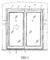
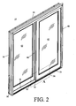
- the sliding patio door (10) of the invention is constructed by a door frame assembly provided with glass installed or without glass installed.
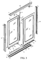
- the sliding patio door (10) of the invention comprises an upper doorframe member (20), a vertical doorframe member (30), a fixed side doorframe member (40), and a lower doorframe member (50) as well as a sliding door panel (61) and a stationary door panel (62).
- the upper doorframe member (20) and the lower doorframe member (50) are shaped and structured by having the cross section as shown in Figure 4 ; while the vertical doorframe member (30) and the fixed side doorframe member (40) are shaped and structured by having the cross section as shown in Figure 14 .
- the vertical doorframe member (30) is provided with a door groove (31), a side groove (33) and a ridge portion (32) located in between the door groove (31) and the side groove (33).
- the door groove (31) formed on the vertical doorframe member (30) is used for accommodating and engaging the side portion of the sliding door panel (61) and to set the door in closed condition
- the side groves (33) formed on the vertical doorframe member (30) is provided for accommodating and engaging the side portion of a screen window (not shown in the drawings) to set the screen window in closed condition.
- a water-tight soft packing strip (34) is provided on the inner wall of the door groove (31) to form tight contact with the surface of the sliding door panel (61) to enable the effect of preventing the water from seeping into the room.
- the fixed-side doorframe member (40) is provided with a ridge portion (41), a door groove (42) and a side groove (43).
- the ridge portion (41) of the fixed-side doorframe member (40) is used to stop the sliding door panel (61) when the sliding door panel (61) is being opened, and the side groves (43) formed on the fixed-side doorframe member (40) is provided for accommodating and engaging the side portion of a screen window (not shown in the drawings) to set the screen window in opened condition.
- the upper doorframe member (20) is provided with a sliding groove (21), a fixing groove (22) and a screen window sliding groove (25).
- the screen window sliding groove (25) has a guide track (26) is provided for mounting a screen window (not shown in the drawings).
- the sliding groove (21) formed on the upper doorframe member (20) is used for holding and engaging with the upper portion of the sliding door panel (61) which can freely slide in a sliding groove (21) formed by two side walls (23) of the upper doorframe member (20), while another fixing groove (22) formed on the upper doorframe member (20) is provided for holding and engaging with the upper portion of the stationary door panel (62). Additionally, a water-tight soft packing strip (24) is provided on the side wall (23) to form tight contact with the surface of the stationary door panel (62) to achieve the effect of preventing water from seeping into the room.
- a bottom rail member (65) of the stationary door panel (62) is installed on a bottom fixing member (75) by way of inserting a positioning rib (76) formed on the bottom fixing member (75) into a connecting groove (66) formed on the bottom rail member (65).
- the lower doorframe member (50) is provided with a skirting portion (51), a sliding rail (52) and a the front portion (53).
- the skirting portion (51) of the lower doorframe member (50) is formed as part of the interior skirting board, and the sliding rail (52) on the lower doorframe member (50) is for mounting a wheel set (90) on the bottom side of the sliding door panel (61) to allow the sliding door panel (61) freely sliding along the sliding rail (52) when it is pulled or pushed along the direction of the track for opening or closing the sliding door panel (61).
- the front portion (53) of the lower doorframe member (50) has an inclined surface sloped down to the front side on which two tenon connecting slots (54) are provided for installing a rain shielding plate (70) and a bottom fixing member (75) to form a complete unit with the lower doorframe member (50).
- a water drainage hole (56) is provided on the lower doorframe member (50) for draining off the water away from the door; besides, further as shown in Figure 4 , on the front bottom surface of the front portion (53) is a tenon connecting slot (55) for installing a connecting board (57) which is located in front of the front portion (53) to form a complete unit with the lower doorframe member (50).
- the connecting board (57) is installed on the front side of the lower doorframe member (50) through the tenon connecting rib (59) with an inclined surface sloped down to the front side to facilitate the draining of water.
- a sliding track (58) is provided on the surface of the connecting board (57) for mounting the screen window jointly with the guide track (26) in the sliding groove (25) of the upper doorframe member (20) to enable the screen window (not shown in the drawings) to slide freely along the sliding track (58).
- the rain shielding plate (70) is made of extruded aluminum alloy which is covered on the upper side of the lower doorframe member (50) together jointly with the adjacent bottom fixing member (75).
- the rain shielding plate (70) is also arranged in inclined position, and is installed on the front portion (53) of the lower doorframe member (50) simply by sliding the tenon connecting rib (72) into the tenon connecting slots (54) to cover the upper side of the front portion (53) of the lower doorframe member (50) to provide the effect of shielding off the rain and rapidly draining off the rainwater away from the door.
- a water shielding rib (71) is provided for blocking the gap between the sliding door panel (61) and the rain shielding plate (70) to prevent the rain water from seeping into the room and provide the effect of wind-shielding.
- a wheel sealing strip (91) is provided in the wheel groove of the bottom rail member (67) of the lower doorframe (61) of this invention as shown in Figure 3 , Figure 4 and Figure 16 .
- the shape of the wheel sealing strip (91) as illustrated in the Figure 3 and 4 is a longitudinal plate with two side walls (93) extended downwardly; on both ends of the longitudinal plate are two holes (92) which provide space for installing the wheel set (90) into a wheel groove formed on a bottom rail member (67) of the sliding door panel (61) when the wheel sealing strip (91) is installed in the wheel groove of the bottom rail member (67) of the sliding door panel (61).
- the side walls (93) on both sides of the wheel sealing strip (91) are properly arranged to shield the gap formed between the wheel set (90) on the bottom side of the sliding door panel (61) and the sliding track (52) of the lower doorframe member (50) to prevent the strong winds and rainwater from seeping into the room.
- the bottom fixing member (75) is an extruded aluminum member comprising a main body having sloped bottom section and a positioning rib (76) formed on the upper surface of the main body.
- the bottom fixing member (75) is installed on the lower doorframe member (50) by sliding the tenon connecting rib (77) into the connecting groove (54) to cover the upper surface of the front portion (53) of the lower doorframe member (50).
- the positioning rib (76) of the bottom fixing member (75) is inserted into the connecting groove (66) of the bottom rail member (65) of the stationery door panel (62) that can securely install the stationery door panel (62) on the main body of the bottom fixing member (75), and have its weight wholly carried by the bottom fixing member (75). Meanwhile, by applying the main body of the bottom fixing member (75) the stationery door panel (62) can be installed in a position in the same height as that of the sliding door panel (61). And then, the stationery door panel (62) is fastened by an L-shaped fastening piece (69) as shown in Figures 4 and 5 to complete the procedure for assembling the stationery door panel (62).
- an end plug (79) is inserted into the bottom fixing member (75) from the side portion to block up the side portion of the main body of the bottom fixing member (75) and make it more pleasing to the eye.
- an opening is provided on inner side of the main body of the bottom fixing member (75) to form a water drainage passage (78).
- a water drainage hole-plug (110) as shown in Figures 17 and 18 is provided in the invention and is installed between the water drainage hole (56) on the lower doorframe member (50) and the bottom fixing member (75) and between the bottom fixing member (75) and the front portion (53) of the lower doorframe member (50) as illustrated in the drawings from Figure 16 through Figure 19 to prevent the strong winds from blowing into the room while allowing the water to be drained off.
- the water drainage hole-plug (110) comprises a frame structure (111) and swinging baffle plate (114) pivotally installed on the frame structure (111) which functioned as a check valve.
- the frame structure has an opening (112) which serves as the inlet of the water drainage passage (78) of the bottom fixing member (75) or the outlet of the water drainage hole (56) on the lower doorframe member (50).
- the frame structure (111) has two pivoting holes (113) on both of its side walls for mounting the shaft (115) of the swinging baffle plate (114) which forms the gate of the opening (112) of the frame structure (111), meanwhile, the frame structure (111) is equipped with positioning rib for restricting the motion of the swinging baffled plate (114).
- the swinging baffle plate (114) When the water is drained off, the swinging baffle plate (114) is pushed to swing out around the shaft (115) to open the outlet (112) of the frame structure (111) to drain off, the water, whereas, when the strong winds blow from outside, the movement of the swinging baffle plate (114) is restricted by the positioning rib on the frame structure (111) to block the outlet (112) to keep the winds out of the room.
- the lower wind shielding block (95) provided by the invention is for sealing up the gap formed between the lower end of the sliding door panel (61) and the lower end of the stationary door panel (62) without affecting the sliding motion of the sliding door panel (61).
- the lower wind shielding block (95) has a main body in stepwise shape which has a flat top surface (97) in horizontal direction, and an inclined bottom surface to fit the slope of the inclined surface of the front portion (53) of the lower doorframe member (50).
- the main body also has a L-shaped slot (96) which is for fitting and installing the L-shaped fastening piece (68) shown in Figure 3 to fix and fasten the wind shielding block (95) to the lower end of the stationery door panel (62), the inner side of the bottom fixing member (75), the front portion (53) and the sliding track (52) of the lower doorframe member (50) and the side surface of the water shielding rib (71) of the water shielding plate (70).
- the upper wind shielding block (27) of the invention has a hopper shaped slot (28) which fits and engages the front edge of the side wall (23) of the fixing groove (22) on the upper doorframe member (20), when the upper wind shielding block (27) is installed on the sliding door panel (61).
- the motion of the sliding door panel (61) shall not be affected by the assembly.
- the upper wind shielding block (27) can seal up the gap formed on the upper end of the sliding door panel (61) and the upper end of the stationary door panel (62).
- a rain shielding strip (80) is provided along the edge of the inner side of the stationary door panel (62) comprising a L-shaped strip (81) and a soft packing strip (82).
- the lower end of the rain shielding strip (80) is arranged to touch the top surface (97) of the lower wind shielding block (95), and, when the sliding door panel (61) is in closed condition, the upper end of the rain shielding strip (80) almost touches the upper wind shielding block (27).
- the gap between the sliding door panel (61) and the stationary door panel (62) can be completely sealed up by the upper wind shielding block (27), the lower wind shielding block (95) and the rain shielding strip (80).
- the tight contact formed between the soft packing strip (82) of the rain shielding strip (80) and the sliding door panel (61) provides the effect of preventing the water from seeping into the room, but also the L-shaped strip (81) of the rain shielding strip (80) of the stationary door panel (62) and another L-shaped strip (86) of the rain shielding strip (85) of the sliding door panel (61) are arranged to extend across each other to form a structure that can effectively prevent the water from seeping into the room.
- a soft packing strip (87) is provided on the rain shielding strip (85) which has its upper end touching the upper wind shielding block (27), and, when the sliding door panel (61) is in closed condition, the lower end of the rain shielding strip (80) almost touches the top surface (97) of the lower wind shielding block (95), therefore, when the sliding door panel (61) is in closed condition the gap between the sliding door panel (61) and the stationary door panel (62) is completely sealed up by the upper wind shielding block (27), lower wind shielding block (95) and the rain shielding strip (85). Further, since the soft packing strip (87) on the rain shielding strip (85) forms tight contact with the stationary door panel (62), it also provides the effect of preventing the water from seeping into the room.
- a soft gastight strip (88) is further provided to increase the gastight-effect of the rain shielding strip (80) and rain shielding strip (85) which are arranged to across each other.
- an anti-lift device (100) is further installed in the sliding groove (21) of the upper doorframe member (20) to enable the sliding door panel (61) to have the effects of anti-lift and anti-burglar.
- the anti-lift device (100) comprises a fastening seat (101) and a rotatable piece (104).
- the fastening seat (101) has an open space (102) for accommodating the rotatable piece (104).
- a recessions (103) is provided for fitting and holding the rotatable piece (104) after it is lifted and rotated an angle of 90 degrees to form the using state as shown in Figure 11 .
- a groove (64) is provided on an upper rail member (63) of the sliding door panel (61) which provides the space for accommodating the anti-lift device (100).
- the upper rail member (63) of the sliding door panel (61) will not interfere with the anti-lift device (100) so that the sliding door panel (61) can be removed or reinstalled.
- the rotatable piece (104) when the rotatable piece (104) is in using state, it will interfere with the upper rail member (63) of the sliding door panel (61) to prevent the lifting of the sliding door panel (61) that achieves the effects of anti-lift and anti-burglar.
- the sliding patio door (10) of the invention has a stopper (29) in the sliding groove (21) of the upper doorframe member (20) positioned near the fixed side doorframe member (40) used for limiting the sliding distance of the sliding door panel (61).
- a soft sealing cover (89) is installed on the vertical side of the sliding door panel (61) to provide cushion effect, when the sliding door panel (61) is pulled to open the door, and hits the stopper (29) mentioned above.
Landscapes
- Engineering & Computer Science (AREA)
- Civil Engineering (AREA)
- Structural Engineering (AREA)
- Specific Sealing Or Ventilating Devices For Doors And Windows (AREA)
- Wing Frames And Configurations (AREA)
Claims (15)
- Structure de porte-fenêtre, comprenant un assemblage de cadre de porte, constitué d'un élément de dormant supérieur (20), d'un élément de dormant vertical (30), d'un élément de dormant de côté fixe (40) et d'un élément de dormant inférieur (50), ainsi qu'un panneau de porte coulissant (61) coulissant librement sur le dormant de porte et un panneau de porte immobile (62) solidement installé sur un élément de fixation inférieur (75) qui est installé et recouvert sur l'élément de dormant inférieur (50) du dormant de porte, dans laquelle
l'élément de dormant supérieur (20) présente une rainure de coulissement (21) utilisée pour retenir et venir en prise avec la partie supérieure du panneau de porte coulissant (61), et une rainure de fixation (22) utilisée pour retenir et venir en prise avec la partie supérieure du panneau de porte immobile (62) ;
l'élément de dormant vertical (30) présente une rainure de porte (31) utilisée pour recevoir et mettre en prise la partie latérale du panneau de porte coulissant (61) lorsqu'il se trouve en position fermée ;
l'élément de dormant de côté fixe (40) présente une partie formant crête (41) utilisée pour arrêter le panneau de porte coulissant (61) lorsqu'il se trouve en position ouverte, et une rainure de porte (42) utilisée pour recevoir et mettre en prise la partie latérale du panneau de porte immobile (62) ;
l'élément de dormant inférieur (50) présente une partie de ceinture (51) servant de plinthe, un rail coulissant (52), utilisé pour monter un ensemble de roulettes (90), qui est installé sur le côté inférieur du panneau de porte coulissant (61), et une partie avant (53) avec une surface inclinée, en pente vers sa face avant, sur laquelle deux mortaises (54) pour tenons sont prévues pour installer un élément de fixation inférieur (75) ;
une nervure de positionnement (76) de l'élément de fixation inférieur (75) est insérée dans l'élément de rail inférieur (65) du panneau de porte immobile (62) ;
caractérisée en ce que l'élément de fixation inférieur (75) est un élément en aluminium extrudé comprenant un corps principal présentant une section inférieure en pente avec deux nervures de raccordement des tenons (77) et une nervure de positionnement (76) formées sur le corps principal, lequel élément de fixation inférieur (75) est installé et recouvert sur l'élément de dormant inférieur (50) en glissant la nervure de raccordement des tenons (77) dans la rainure de liaison (54) de l'élément de dormant inférieur (50). - Structure de porte-fenêtre selon la revendication 1, dans laquelle le panneau de porte coulissant (61) et le panneau de porte immobile (62) sont vitrés.
- Structure de porte-fenêtre selon la revendication 1 ou 2, dans laquelle la rainure de porte (31) de l'élément de dormant vertical (30) est munie d'une baguette d'enrobage souple étanche à l'eau (34) ou la rainure de porte (41) de l'élément de dormant côté fixe (40) est munie d'une baguette d'enrobage souple étanche à l'eau (44).
- Structure de porte-fenêtre selon la revendication 1, 2 ou 3, dans laquelle l'élément de dormant inférieur (50) présente un panneau de liaison (57) installée en face de sa partie avant (53).
- Structure de porte-fenêtre selon la revendication 1, 2, 3 ou 4, dans laquelle l'élément de dormant inférieur (50) présente une plaque de protection contre la pluie (70) installée et recouverte sur sa partie avant (53) et la plaque de protection contre la pluie (70) présente une nervure anti-pénétration d'eau (71) prévue pour bloquer l'interstice entre le panneau de porte coulissant (61) et la plaque de protection contre la pluie (70).
- Structure de porte-fenêtre selon la revendication 1 ou 2, dans laquelle une baguette d'étanchéité des roulettes (91) est installé sur le côté inférieur du panneau de porte coulissant (61) afin d'étanchéifier l'ensemble de roulettes (90).
- Structure de porte-fenêtre selon la revendication 1 ou 2, dans laquelle l'élément de dormant inférieur (50) présente un trou d'évacuation d'eau (56) et le côté intérieur du corps principal de l'élément de fixation inférieur (75) présente un passage d'évacuation d'eau (78).
- Structure de porte-fenêtre selon la revendication 7, dans laquelle un cache-trou d'évacuation d'eau (110) est respectivement installé entre le trou d'évacuation d'eau (56) de l'élément de dormant inférieur (50) et l'élément de fixation inférieur (75) et entre l'élément de fixation inférieur (75) et la partie avant (53) de l'élément de dormant inférieur (50), avec une fonction de clapet de non-retour, comprenant une structure de cadre (111) et une chicane oscillante (114) installé sur la structure de cadre (111) de façon à pouvoir pivoter.
- Structure de porte-fenêtre selon la revendication 1 ou 2, dans laquelle un bloc coupe-vent inférieur (95) est utilisé pour obturer l'interstice formé entre l'extrémité inférieure du panneau de porte coulissant (61) et l'extrémité inférieure du panneau de porte immobile (62) sans affecter le mouvement de coulissement du panneau de porte coulissant (61).
- Structure de porte-fenêtre selon la revendication 1, 2, 5 ou 9, dans laquelle un bloc coupe-vent supérieur (27) avec une fente en forme de trémie (28) est utilisé pour obturer l'interstice formé entre l'extrémité supérieure du panneau de porte coulissant (61) et l'extrémité supérieure du panneau de porte immobile (62).
- Structure de porte-fenêtre selon la revendication 1 ou 2, dans laquelle une baguette de protection contre la pluie (80) comprenant une baguette en forme de L (81) et une baguette d'enrobage souple (82) est prévue le long du bord du côté intérieur du panneau de porte immobile (62) et une baguette de protection contre la pluie (85) comprenant une baguette en forme de L (86) et une baguette d'enrobage souple (87) est prévue le long du bord du côté intérieur du panneau de porte coulissant (61).
- Structure de porte-fenêtre selon la revendication 1 ou 2, dans laquelle un dispositif anti-soulèvement (100), comprenant une embase de fixation (101) et une pièce rotative (104) est en outre installée dans la rainure de coulissement (21) de l'élément de dormant supérieur (20).
- Structure de porte-fenêtre selon la revendication 1 ou 2, dans laquelle une butée (29) utilisée pour limiter la distance de coulissement du panneau de porte coulissant (61) est installée dans la rainure de coulissement (21) de l'élément de dormant supérieur (20).
- Structure de porte-fenêtre selon la revendication 1 ou 2, dans laquelle un couvercle d'étanchéité souple (89) est installé sur le côté vertical du panneau de porte coulissant (61).
- Structure de porte-fenêtre selon la revendication 4, dans laquelle l'élément de dormant supérieur (20) présente une rainure de coulissement (25) avec un chemin de guidage (26) et le panneau de liaison (57) présente un chemin de coulissement (58) conjoint pour permettre d'y installer une fenêtre-moustiquaire.
Priority Applications (1)
| Application Number | Priority Date | Filing Date | Title |
|---|---|---|---|
| EP20040024251 EP1647660B1 (fr) | 2004-10-12 | 2004-10-12 | Structure d' une porte pour une cour intérieure |
Applications Claiming Priority (1)
| Application Number | Priority Date | Filing Date | Title |
|---|---|---|---|
| EP20040024251 EP1647660B1 (fr) | 2004-10-12 | 2004-10-12 | Structure d' une porte pour une cour intérieure |
Publications (2)
| Publication Number | Publication Date |
|---|---|
| EP1647660A1 EP1647660A1 (fr) | 2006-04-19 |
| EP1647660B1 true EP1647660B1 (fr) | 2012-12-19 |
Family
ID=34926949
Family Applications (1)
| Application Number | Title | Priority Date | Filing Date |
|---|---|---|---|
| EP20040024251 Expired - Lifetime EP1647660B1 (fr) | 2004-10-12 | 2004-10-12 | Structure d' une porte pour une cour intérieure |
Country Status (1)
| Country | Link |
|---|---|
| EP (1) | EP1647660B1 (fr) |
Families Citing this family (10)
| Publication number | Priority date | Publication date | Assignee | Title |
|---|---|---|---|---|
| AT10062U3 (de) * | 2008-03-12 | 2009-02-15 | Josko Fenster Und Tueren Gmbh | Dichtungsanordnung für schiebetüren |
| CN107335650A (zh) * | 2017-08-30 | 2017-11-10 | 温树宝 | 飞轮清洗装置 |
| CN109707302B (zh) * | 2019-01-17 | 2023-10-20 | 佛山市卡洛斯恩门窗有限公司 | 一种组装式庭院门 |
| CN113775279B (zh) * | 2021-08-13 | 2023-05-23 | 华北水利水电大学 | 一种家用地下室入户门防进水闸门 |
| CN114033291B (zh) * | 2021-11-24 | 2023-06-23 | 安徽欣万顺安全装备科技有限公司 | 一种船用单扇气密门 |
| CN114607246B (zh) * | 2022-03-11 | 2023-09-26 | 黄山市皖金铝业科技有限公司 | 一种多功能铝合金门窗 |
| CN114809868B (zh) * | 2022-04-13 | 2023-08-22 | 浙江海博门业有限公司 | 一种具有抗风减震功能景观居室门 |
| CN114737866B (zh) * | 2022-04-16 | 2023-10-03 | 嘉兴市盛华人防设备有限公司 | 一种抗击爆炸冲击结构及人防门 |
| CN115522848A (zh) * | 2022-10-18 | 2022-12-27 | 哈尔滨华兴节能门窗股份有限公司 | 一种铝包木提升推拉门上侧密封结构 |
| CN118997635B (zh) * | 2024-10-21 | 2025-01-24 | 湖南胜捷泰安消防科技有限公司 | 一种医院病房用快拆式隔离门 |
Family Cites Families (2)
| Publication number | Priority date | Publication date | Assignee | Title |
|---|---|---|---|---|
| US3530618A (en) * | 1968-10-09 | 1970-09-29 | Panascope Inc | Composite door and window construction |
| FR2804461B1 (fr) | 2000-01-31 | 2002-09-13 | Hutchinson | Chassis coulissant pour porte-fenetre |
-
2004
- 2004-10-12 EP EP20040024251 patent/EP1647660B1/fr not_active Expired - Lifetime
Also Published As
| Publication number | Publication date |
|---|---|
| EP1647660A1 (fr) | 2006-04-19 |
Similar Documents
| Publication | Publication Date | Title |
|---|---|---|
| AU616988B2 (en) | Self-draining panel threshold combination | |
| KR100412746B1 (ko) | 수평슬라이딩폐쇄조립체용배수시스템 | |
| KR100901994B1 (ko) | 레일 은폐 구조를 갖는 창호장치 | |
| EP1647660B1 (fr) | Structure d' une porte pour une cour intérieure | |
| US4125141A (en) | Self draining frame structure | |
| KR200183376Y1 (ko) | 레일은폐형 창호(또는 문)장치 | |
| WO2020228439A1 (fr) | Obturateur articulé à oscillation unidirectionnelle, toit à lanterneau à obturateur articulé et lames d'obturateur | |
| KR200242636Y1 (ko) | 리프트 슬라이딩 창문의 배수 구조 | |
| CN209384853U (zh) | 一种严密的推拉窗 | |
| CN209561902U (zh) | 一种电表箱上的可视窗结构 | |
| KR102075380B1 (ko) | 창호 시스템 | |
| KR101366456B1 (ko) | 실외 장착형 글레이징 비드를 구비한 창호 및 그 조립 방법 | |
| KR20190062810A (ko) | 슬라이딩 개폐방식의 창호가 설치된 문틀의 원활한 배수 및 외풍방지를 위한 가스켓 조립구조 | |
| DK180661B1 (en) | Roof window with covering arrangement | |
| JPH025036Y2 (fr) | ||
| KR100493897B1 (ko) | 무레일형 창호장치 | |
| JPS593106Y2 (ja) | 戸袋の気密装置 | |
| JPH09209664A (ja) | 引違いサッシの召合せ部水密構造 | |
| US20070266653A1 (en) | Combination window, screen, storm shutter and fire escape | |
| CN217760666U (zh) | 一种带纱窗的双轨道推拉窗 | |
| JP7539275B2 (ja) | 排水弁装置及びサッシ窓 | |
| JP3934077B2 (ja) | 戸当り、およびこの戸当りを備えた窓 | |
| JP3110616U (ja) | パティオドア | |
| JPH06200677A (ja) | 内倒し窓 | |
| KR0121348Y1 (ko) | 창문용 환기구 |
Legal Events
| Date | Code | Title | Description |
|---|---|---|---|
| PUAI | Public reference made under article 153(3) epc to a published international application that has entered the european phase |
Free format text: ORIGINAL CODE: 0009012 |
|
| AK | Designated contracting states |
Kind code of ref document: A1 Designated state(s): AT BE BG CH CY CZ DE DK EE ES FI FR GB GR HU IE IT LI LU MC NL PL PT RO SE SI SK TR |
|
| AX | Request for extension of the european patent |
Extension state: AL HR LT LV MK |
|
| 17P | Request for examination filed |
Effective date: 20061019 |
|
| AKX | Designation fees paid |
Designated state(s): DE ES FR GB IT NL |
|
| GRAP | Despatch of communication of intention to grant a patent |
Free format text: ORIGINAL CODE: EPIDOSNIGR1 |
|
| GRAS | Grant fee paid |
Free format text: ORIGINAL CODE: EPIDOSNIGR3 |
|
| GRAA | (expected) grant |
Free format text: ORIGINAL CODE: 0009210 |
|
| AK | Designated contracting states |
Kind code of ref document: B1 Designated state(s): DE ES FR GB IT NL |
|
| REG | Reference to a national code |
Ref country code: GB Ref legal event code: FG4D |
|
| REG | Reference to a national code |
Ref country code: DE Ref legal event code: R096 Ref document number: 602004040429 Country of ref document: DE Effective date: 20130214 |
|
| REG | Reference to a national code |
Ref country code: NL Ref legal event code: T3 |
|
| PG25 | Lapsed in a contracting state [announced via postgrant information from national office to epo] |
Ref country code: ES Free format text: LAPSE BECAUSE OF FAILURE TO SUBMIT A TRANSLATION OF THE DESCRIPTION OR TO PAY THE FEE WITHIN THE PRESCRIBED TIME-LIMIT Effective date: 20130330 |
|
| PLBE | No opposition filed within time limit |
Free format text: ORIGINAL CODE: 0009261 |
|
| STAA | Information on the status of an ep patent application or granted ep patent |
Free format text: STATUS: NO OPPOSITION FILED WITHIN TIME LIMIT |
|
| 26N | No opposition filed |
Effective date: 20130920 |
|
| PG25 | Lapsed in a contracting state [announced via postgrant information from national office to epo] |
Ref country code: IT Free format text: LAPSE BECAUSE OF FAILURE TO SUBMIT A TRANSLATION OF THE DESCRIPTION OR TO PAY THE FEE WITHIN THE PRESCRIBED TIME-LIMIT Effective date: 20121219 |
|
| REG | Reference to a national code |
Ref country code: DE Ref legal event code: R097 Ref document number: 602004040429 Country of ref document: DE Effective date: 20130920 |
|
| REG | Reference to a national code |
Ref country code: FR Ref legal event code: PLFP Year of fee payment: 12 |
|
| REG | Reference to a national code |
Ref country code: FR Ref legal event code: PLFP Year of fee payment: 13 |
|
| REG | Reference to a national code |
Ref country code: FR Ref legal event code: PLFP Year of fee payment: 14 |
|
| REG | Reference to a national code |
Ref country code: FR Ref legal event code: PLFP Year of fee payment: 15 |
|
| PGFP | Annual fee paid to national office [announced via postgrant information from national office to epo] |
Ref country code: NL Payment date: 20231026 Year of fee payment: 20 |
|
| PGFP | Annual fee paid to national office [announced via postgrant information from national office to epo] |
Ref country code: GB Payment date: 20231013 Year of fee payment: 20 |
|
| PGFP | Annual fee paid to national office [announced via postgrant information from national office to epo] |
Ref country code: FR Payment date: 20231030 Year of fee payment: 20 Ref country code: DE Payment date: 20230919 Year of fee payment: 20 |
|
| REG | Reference to a national code |
Ref country code: DE Ref legal event code: R071 Ref document number: 602004040429 Country of ref document: DE |
|
| REG | Reference to a national code |
Ref country code: NL Ref legal event code: MK Effective date: 20241011 |
|
| REG | Reference to a national code |
Ref country code: GB Ref legal event code: PE20 Expiry date: 20241011 |
|
| PG25 | Lapsed in a contracting state [announced via postgrant information from national office to epo] |
Ref country code: GB Free format text: LAPSE BECAUSE OF EXPIRATION OF PROTECTION Effective date: 20241011 |
|
| PG25 | Lapsed in a contracting state [announced via postgrant information from national office to epo] |
Ref country code: GB Free format text: LAPSE BECAUSE OF EXPIRATION OF PROTECTION Effective date: 20241011 |