EP1647719A2 - Soupape hydraulique avec fonction de régénération - Google Patents
Soupape hydraulique avec fonction de régénération Download PDFInfo
- Publication number
- EP1647719A2 EP1647719A2 EP20050018113 EP05018113A EP1647719A2 EP 1647719 A2 EP1647719 A2 EP 1647719A2 EP 20050018113 EP20050018113 EP 20050018113 EP 05018113 A EP05018113 A EP 05018113A EP 1647719 A2 EP1647719 A2 EP 1647719A2
- Authority
- EP
- European Patent Office
- Prior art keywords
- fluid passage
- regeneration
- pressure
- fluid
- tank
- Prior art date
- Legal status (The legal status is an assumption and is not a legal conclusion. Google has not performed a legal analysis and makes no representation as to the accuracy of the status listed.)
- Granted
Links
- 230000008929 regeneration Effects 0.000 title claims abstract description 122
- 238000011069 regeneration method Methods 0.000 title claims abstract description 122
- 239000012530 fluid Substances 0.000 claims abstract description 244
- 230000008859 change Effects 0.000 claims abstract description 15
- 238000007599 discharging Methods 0.000 claims abstract description 6
- 238000010276 construction Methods 0.000 description 3
- 238000000034 method Methods 0.000 description 2
- 230000008569 process Effects 0.000 description 2
- 230000001172 regenerating effect Effects 0.000 description 2
- 230000004048 modification Effects 0.000 description 1
- 238000012986 modification Methods 0.000 description 1
Images




Classifications
-
- F—MECHANICAL ENGINEERING; LIGHTING; HEATING; WEAPONS; BLASTING
- F15—FLUID-PRESSURE ACTUATORS; HYDRAULICS OR PNEUMATICS IN GENERAL
- F15B—SYSTEMS ACTING BY MEANS OF FLUIDS IN GENERAL; FLUID-PRESSURE ACTUATORS, e.g. SERVOMOTORS; DETAILS OF FLUID-PRESSURE SYSTEMS, NOT OTHERWISE PROVIDED FOR
- F15B13/00—Details of servomotor systems ; Valves for servomotor systems
- F15B13/02—Fluid distribution or supply devices characterised by their adaptation to the control of servomotors
- F15B13/04—Fluid distribution or supply devices characterised by their adaptation to the control of servomotors for use with a single servomotor
- F15B13/0401—Valve members; Fluid interconnections therefor
- F15B13/0402—Valve members; Fluid interconnections therefor for linearly sliding valves, e.g. spool valves
- F15B13/0403—Valve members; Fluid interconnections therefor for linearly sliding valves, e.g. spool valves a secondary valve member sliding within the main spool, e.g. for regeneration flow
-
- E—FIXED CONSTRUCTIONS
- E02—HYDRAULIC ENGINEERING; FOUNDATIONS; SOIL SHIFTING
- E02F—DREDGING; SOIL-SHIFTING
- E02F9/00—Component parts of dredgers or soil-shifting machines, not restricted to one of the kinds covered by groups E02F3/00 - E02F7/00
- E02F9/20—Drives; Control devices
- E02F9/22—Hydraulic or pneumatic drives
- E02F9/2217—Hydraulic or pneumatic drives with energy recovery arrangements, e.g. using accumulators, flywheels
-
- E—FIXED CONSTRUCTIONS
- E02—HYDRAULIC ENGINEERING; FOUNDATIONS; SOIL SHIFTING
- E02F—DREDGING; SOIL-SHIFTING
- E02F9/00—Component parts of dredgers or soil-shifting machines, not restricted to one of the kinds covered by groups E02F3/00 - E02F7/00
- E02F9/20—Drives; Control devices
- E02F9/22—Hydraulic or pneumatic drives
- E02F9/2264—Arrangements or adaptations of elements for hydraulic drives
- E02F9/2267—Valves or distributors
-
- F—MECHANICAL ENGINEERING; LIGHTING; HEATING; WEAPONS; BLASTING
- F15—FLUID-PRESSURE ACTUATORS; HYDRAULICS OR PNEUMATICS IN GENERAL
- F15B—SYSTEMS ACTING BY MEANS OF FLUIDS IN GENERAL; FLUID-PRESSURE ACTUATORS, e.g. SERVOMOTORS; DETAILS OF FLUID-PRESSURE SYSTEMS, NOT OTHERWISE PROVIDED FOR
- F15B11/00—Servomotor systems without provision for follow-up action; Circuits therefor
- F15B11/02—Systems essentially incorporating special features for controlling the speed or actuating force of an output member
- F15B11/024—Systems essentially incorporating special features for controlling the speed or actuating force of an output member by means of differential connection of the servomotor lines, e.g. regenerative circuits
-
- F—MECHANICAL ENGINEERING; LIGHTING; HEATING; WEAPONS; BLASTING
- F15—FLUID-PRESSURE ACTUATORS; HYDRAULICS OR PNEUMATICS IN GENERAL
- F15B—SYSTEMS ACTING BY MEANS OF FLUIDS IN GENERAL; FLUID-PRESSURE ACTUATORS, e.g. SERVOMOTORS; DETAILS OF FLUID-PRESSURE SYSTEMS, NOT OTHERWISE PROVIDED FOR
- F15B13/00—Details of servomotor systems ; Valves for servomotor systems
- F15B13/02—Fluid distribution or supply devices characterised by their adaptation to the control of servomotors
- F15B13/021—Valves for interconnecting the fluid chambers of an actuator
-
- B—PERFORMING OPERATIONS; TRANSPORTING
- B60—VEHICLES IN GENERAL
- B60Y—INDEXING SCHEME RELATING TO ASPECTS CROSS-CUTTING VEHICLE TECHNOLOGY
- B60Y2200/00—Type of vehicle
- B60Y2200/40—Special vehicles
- B60Y2200/41—Construction vehicles, e.g. graders, excavators
- B60Y2200/412—Excavators
-
- Y—GENERAL TAGGING OF NEW TECHNOLOGICAL DEVELOPMENTS; GENERAL TAGGING OF CROSS-SECTIONAL TECHNOLOGIES SPANNING OVER SEVERAL SECTIONS OF THE IPC; TECHNICAL SUBJECTS COVERED BY FORMER USPC CROSS-REFERENCE ART COLLECTIONS [XRACs] AND DIGESTS
- Y10—TECHNICAL SUBJECTS COVERED BY FORMER USPC
- Y10T—TECHNICAL SUBJECTS COVERED BY FORMER US CLASSIFICATION
- Y10T137/00—Fluid handling
- Y10T137/8593—Systems
- Y10T137/86493—Multi-way valve unit
- Y10T137/86574—Supply and exhaust
- Y10T137/86622—Motor-operated
- Y10T137/8663—Fluid motor
-
- Y—GENERAL TAGGING OF NEW TECHNOLOGICAL DEVELOPMENTS; GENERAL TAGGING OF CROSS-SECTIONAL TECHNOLOGIES SPANNING OVER SEVERAL SECTIONS OF THE IPC; TECHNICAL SUBJECTS COVERED BY FORMER USPC CROSS-REFERENCE ART COLLECTIONS [XRACs] AND DIGESTS
- Y10—TECHNICAL SUBJECTS COVERED BY FORMER USPC
- Y10T—TECHNICAL SUBJECTS COVERED BY FORMER US CLASSIFICATION
- Y10T137/00—Fluid handling
- Y10T137/8593—Systems
- Y10T137/86493—Multi-way valve unit
- Y10T137/86574—Supply and exhaust
- Y10T137/8667—Reciprocating valve
- Y10T137/86694—Piston valve
- Y10T137/8671—With annular passage [e.g., spool]
Definitions
- the present invention relates in general to a hydraulic control valve with a regeneration function for heavy construction equipment such as an excavator, more specifically, to a hydraulic control valve capable of maintaining the pressure in a regeneration fluid passage, irrespective of changes in the discharge flow rate of a hydraulic pump, the location of working equipment, the regeneration flow rate and the return flow rate.
- a hydraulic control valve for use in heavy construction equipment had two functions: firstly, it controls the flow of pressurized fluid discharged from a hydraulic pump and supplies it to an actuator, e.g., a hydraulic cylinder; and secondly, it sends pressurized fluid returning during the operation of the hydraulic cylinder to a tank.
- an actuator e.g., a hydraulic cylinder
- a hydraulic control valve of recent years now has a regeneration function, whereby part of the pressurized fluid returning to the tank is supplied back to the hydraulic cylinder.
- the hydraulic control valve with a regeneration function sends the return pressurized fluid en route to the tank back to the hydraulic cylinder.
- the work speed and the energy efficiency can be increased.
- Cavitation usually occurs at insufficiency of a flow rate into the chamber of the hydraulic cylinder and causes each component's life to be shorten. When actions for cavitation preventing are taken, the components' life can thus be extended.
- Fig. 1 is a cross-sectional view of a related art hydraulic control valve with a regeneration function
- Fig. 2 is a partial exploded view of a regeneration valve in Fig. 1
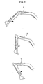
- Fig. 3 is a schematic view illustrating an example of the operation of a working equipment. The following will now describe the operation of a hydraulic control valve 3.
- a pressurized fluid discharged from a hydraulic pump 1 is supplied to the hydraulic control valve 3 through a feed line (or supply line) 2.
- a feed line or supply line
- the pressurized fluid of the hydraulic pump 1 is supplied to a first port 4 or a second port 5 via a supply fluid passage 6.
- the first port 4 is connected to a large chamber 8a of a hydraulic cylinder 8, and the second port 5 is connected to a small chamber 8b thereof.
- pressurized fluid is supplied to the large chamber 8a through the first port 4, and the hydraulic cylinder 8 is extended to the right side.
- the pressurized fluid discharged from the small chamber 8b returns to a reservoir or a storage tank T by way of the second port 5 and a tank fluid passage 10b.
- pressurized fluid is supplied to the small chamber 8b through the second port 5, and the hydraulic cylinder 8 is retracted to the left side. Meanwhile, the pressurized fluid discharged from the large chamber 8a returns to the tank T by way of the first port 4 and the tank fluid passage 10a.
- the pressurized fluid discharged from the small chamber 8b sequentially passes through the second port 5, first regeneration fluid passage 13, connection fluid passage 14, return fluid passage 16, and tank fluid passage 10b. Because the original area of the return fluid passage 16 is small, a pressure is created in the first regeneration fluid passage 13. If this pressure is higher than the pressure in a second generation fluid passage 15, a poppet 9 housed in the spool 7 moves to the right side, and the pressurized fluid of the first generation fluid passage 13 flows into the direction of the supply fluid passage 6 through the second regeneration fluid passage 15.
- the pressure of the second port 5 should be lower than the pressure of the first port 4. That is, the lower the pressure of the first regeneration fluid passage 13, the larger the operational force for the hydraulic cylinder 8.
- the regeneration spool 22 is elastically supported by a spring 23, and its front part comes in contact with a piston 21 which moves by the pressure from the supply fluid passage 6.
- a designated value the piston 21 of the regeneration valve 12 is pressed by the pressure from the supply fluid passage 6, and the regeneration spool 22 moves to the right side.
- the area of the return fluid passage 16 gradually increases and the pressure of the first regeneration fluid passage 13 is lowered accordingly, providing a larger force for the operation of the hydraulic cylinder 8.
- the flow rate Q is related to several variables, e.g., the feed rate of the hydraulic pump 1, the location of a working equipment shown in Fig. 3 for example, and the flow regenerated through the second regeneration fluid passage 15.
- the change of pressure of the first regeneration fluid passage 13 and the pressure in the supply fluid passage 6 react sensitively to the flow rate Q and the area A.
- the change of the pressures in the first and second ports 4, 5 make the motion of the hydraulic cylinder unnatural and awkward (this phenomenon is called hunting) as a result of poor hydraulic stability. Therefore, it becomes very difficult to control the motion of the hydraulic cylinder 8.
- an object of the present invention to provide a hydraulic control valve with a regeneration function, capable of maintaining the pressure in a regeneration fluid passage, irrespective of changes in the discharge flow rate of a hydraulic pump, the location of working equipment, the regeneration flow rate and the return flow rate.
- a hydraulic control valve equipped with a regeneration valve, in which the regeneration valve regenerates the return fluid from the hydraulic cylinder and supplies it to a supply fluid passage, and maintains the pressure of a regeneration fluid passage at a constant level in accordance with the change of pressure of the supply fluid passage.
- the present invention provides a hydraulic control valve with a regeneration function, including: a main body formed of a supply fluid passage to which pressurized fluid from outside is supplied, at least one port for supplying the pressurized fluid in the supply fluid passage to an actuator or receiving the return fluid from the actuator, a tank fluid passage for discharging the return fluid from the actuator to an outside storage tank, and a first regeneration fluid passage for supplying part of the return fluid from the actuator to the supply fluid passage; a spool movably installed inside the main body for controlling the flow of pressurized fluid by opening/closing the connections of the supply fluid passage, the port(s), the tank fluid passage, and the first regeneration fluid passage, respectively, and comprising a second generation fluid passage that supplies the pressurized fluid of the first regeneration fluid passage to the supply fluid passage; and a regeneration valve installed between the first regeneration fluid passage and the tank fluid passage for returning only part of the pressurized fluid of the first regeneration fluid passage to the tank fluid passage to maintain pressure of the first regeneration fluid passage at a designated value, and for
- the regeneration valve includes a sleeve installed between the first regeneration fluid passage and the tank fluid passage, and formed of a first fluid passage communicating with the first regeneration fluid passage and a second fluid passage communicating with the tank fluid passage; a main poppet movably installed inside the sleeve by being elastically supported by a first spring for changing an opening area of the second fluid passage, and comprising a back pressure chamber formed therein; a pilot poppet movably installed inside the sleeve by being elastically supported by a second spring, and if pressure of the back pressure chamber exceeds a predetermined pressure, discharging pressurized fluid of the back pressure chamber to the tank fluid passage; a pilot piston movably installed on a piston passage formed in front of the main poppet to be in contact with the front end portion of the pilot poppet; and a piston slidably installed on the front side of the sleeve for the rear end of the piston to be in contact with the front end portion of the pilot piston, and if the pressure of the supply fluid passage applied
- the hydraulic control valve of the present invention further includes a pressure regulator installed on the rear end of the regeneration valve for assisting the second spring to change the predetermined pressure set for the pilot poppet.
- the pressure regulator is operated by a signal pressure inputted from outside.
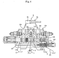
- Fig. 4 is a cross-sectional view of a hydraulic control valve according to one embodiment of the present invention
- Fig. 5 is a partial exploded view of a regeneration valve in the hydraulic control valve of Fig. 4.
- the hydraulic control valve with a regeneration function of the present invention supplies pressurized fluid to a hydraulic cylinder 8, one of actuators, and controls the operation thereof.
- the hydraulic control valve includes a main body 103 in which fluid passages for pressurized fluid are formed; a spool 107 slidably installed in the main body 103 for supplying pressurized fluid to the hydraulic cylinder 8; and a regeneration valve 112 for regenerating part of the pressurized fluid returning from the hydraulic cylinder 8.
- Examples of the fluid passages formed in the main body 103 include a supply fluid passage 106 to which pressurized fluid discharged from a hydraulic pump 1 is supplied; a first port 104 and a second port 105 for supplying the pressurized fluid in the supply fluid passage 106 to the hydraulic cylinder 8, or receiving the return fluid from the hydraulic cylinder 8; and tank fluid passages 110a, 110b for discharging the return fluid from the hydraulic cylinder 8 to a storage tank T (e.g., reservoir).
- the main body 103 includes a first regeneration fluid passage 113 for supplying pressurized fluid returning from the hydraulic cylinder 8 to the supply fluid passage 106, and regenerating the return fluid.
- the spool 107 is slidably installed (e.g., in the lateral direction on the drawing) inside the main body 103.
- the spool 107 opens/closes the connections of the supply fluid passage 106, the first and second ports 104, 105, the tank fluid passage 110a, 110b, and the first regeneration fluid passage 113, respectively, in order to control the flow of pressurized fluid.
- a second regeneration fluid passage 115 that supplies the pressurized fluid of the first regeneration fluid passage 113 to the supply fluid passage 106.
- a poppet 109 is slidably installed in the longitudinal direction of the second regeneration fluid passage 115.
- the poppet 109 moves to the right side and thereby, flowing the pressurized fluid of the first regeneration fluid passage 113 into the direction of the supply fluid passage 106 through the second regeneration fluid passage 115.
- the regeneration valve 112 is installed between the first regeneration passage 113 and the tank fluid passage 110b so that only a part of pressurized fluid in the first regeneration passage 113 returns to the tank fluid passage 110b. As a result, the pressure of the regeneration passage 113 is maintained regularly, and the regeneration function of supplying the pressurized fluid to the second regeneration passage 115 is carried out.
- the regeneration valve 112 includes a sleeve 120 installed between the first regeneration fluid passage 113 and the tank fluid passage 110b inside the main body 103; a main poppet 134 slidably installed in the sleeve 120; a pilot poppet 133 installed on the rear side of the main poppet 134; a pilot piston 136 slidably installed, passing through the main poppet 134; and a piston 135 slidably installed on the front side of the sleeve 120.
- the sleeve 120 of the regeneration valve 112 is formed of three bodies, namely, a first body 121, a second body 122, and a third body 123, being sequentially connected. Inside the second body 122 is a first fluid passage 124 communicating with the first regeneration fluid passage 113, and a second fluid passage 125 communicating with the tank fluid passage 110b.
- the main poppet 134 being elastically supported by a first spring 137, is slidably installed inside the sleeve 120. If the main poppet 134 translates laterally inside the sleeve 120, the opening area of the second fluid passage 125 changes. Moreover, the main poppet 134 has a back pressure chamber 132, that opens towards the back.
- the pilot poppet 133 being elastically supported by a second spring 138, is slidably installed inside the sleeve 120.
- the pressure from the supply fluid passage 106 moves the piston 135 to the right side, and because of this, the pilot piston 136 and the pilot poppet 133 in contact with the piston 135 move to the right side as well.
- pressurized fluid of the back pressure chamber 132 passes through a discharge fluid passage 150, and is discharged through a separate external drain 151, or (although not shown) if the discharge fluid passage 150 is communicated with the tank fluid passage 110b the pressurized fluid of the back pressure chamber 132 can be discharged to the storage tank T.
- the main poppet 134 also moves to the right side, and the pressurized fluid of the first regeneration fluid passage 113 travels to the connection fluid passage 114 and the second fluid passage 125, and eventually is discharged to the tank fluid passage 110b.
- the rear end portion of the pilot piston 136 comes in contact with the front end portion of the pilot poppet 133, whereas the front end portion of the pilot piston 136 passes through a piston passage 134b formed in front of the main poppet 134, whereby the pilot piston 136 can slide with respect to the main poppet 134.
- the rear end portion of the piston 135 comes in contact with the front end portion of the pilot piston 136, whereas the front end portion of the piston 135 is movably inserted into a front passage 135b of the first body 121 of sleeve 120.
- the pressure of the supply fluid passage 106 is applied to the front end portion of the piston 135.
- the piston 135 pressurizes the pilot piston 136 and the pilot poppet 133 backward.
- Pressurized fluid discharged from the hydraulic pump 1 is supplied to the hydraulic control valve 103 through the supply fluid passage 2.
- the pressurized fluid of the hydraulic pump 1 is supplied to the first port 104 or the second port 105 through the supply fluid passage 106.
- the pressurized fluid is supplied to the large chamber 8a through the first port 104.
- the hydraulic cylinder 8 is extended to the right side, and the pressurized fluid discharged from the small chamber 8b returns to the storage tank T via the second port 105 and the tank fluid passage 110b.
- part of the return fluid is regenerated by the regeneration valve 112 and flows into the supply fluid passage 106.
- the pressure formed in the supply fluid passage 106 is higher than the pressure of the pilot poppet 133 predetermined by the second spring 138, the pilot poppet 133 will be shift to right so that the back pressure chamber 132 is opened to the tank passage portion 110b. This means to drop the pressure of regeneration passage 113. Therefore, the pressure of supply passage 106 can be used to move the cylinder 8, it is connected an attachment, with more power.
- the regeneration process is performed when the pressure of the supply fluid passage 106 is lower than the predetermined pressure.
- the pressurized fluid discharged from the small chamber 8b of the hydraulic cylinder 8 is supplied to the first regeneration fluid passage 113 via the second port 105. Then, it sequentially passes through the first and second fluid passages 124, 125 of the regeneration valve 112, and returns to the storage tank T through the tank fluid passage 110b.
- the pressure of the first regeneration fluid passage 113 is not much affected by the change of the flow rate, but maintains a constant level. Thus, hunting does not occur and the motion of the hydraulic cylinder 8 can be controlled gently.
- the regeneration valve 112 lowers the pressure of the first regeneration fluid passage 113. So that the pressure of supply passage 106 is used to move the cylinder 8, it is connected an attachment, with more power.
- the pilot poppet 133 is elastically supported by the second spring 138, and this makes setting pressure predetermined. Meanwhile, the pressure of the supply fluid passage 106 is applied to the front end portion of the piston 135. If the pressure of the supply fluid passage 106 exceeds the predetermined pressure of the pilot poppet 133, the piston 135 pressurizes the pilot piston 136 and the pilot poppet 133 backward.
- the pressure created in the first regeneration fluid passage 113 is reduced proportionally to an increase of pressure of the supply fluid passage 106.
- the change of pressure of the supply fluid passage 106 connected to the first regeneration fluid passage 113 becomes very small, and the motion of the hydraulic cylinder 8 is stabilized without being unnatural or awkward (i.e., hunting).
- Fig. 6 graphically illustrates the change of pressure in the hydraulic control valve according to one embodiment of the present invention.
- PR denotes an applied pressure to the first regeneration fluid passage
- Px denotes a signal pressure inputted from outside
- P denotes an applied pressure of the supply fluid passage
- A, B and C denote arbitrary input values from outside (A ⁇ B ⁇ C).
- the ratio of the pressure of the supply fluid passage 106 to the pressure of the first regeneration fluid passage 113 can be controlled in dependence of the size correlation between the piston 135 and the pilot poppet 133.
- Fig. 7 is a partial cross-sectional view of a regeneration valve for a hydraulic control valve according to another embodiment of the present invention.
- the regeneration valve 212 of a hydraulic control valve is operated additionally by a signal pressure Px inputted from outside.
- a signal pressure Px is inputted from outside through a signal-inlet 242
- a pressure piston 243 whose rear side is supported by a third spring 241 pressurizes the rear end of the pilot poppet 133, whereby the piston 243 together with a second spring 138 changes a predetermined pressure set for the pilot poppet 133.
- Fig. 6(b) briefly illustrates the relation between the pressure of the supply fluid passage 106 and the pressure of the first regeneration fluid passage 113.
- Fig. 8 is a partial cross-sectional view of a regeneration valve in a hydraulic control valve according to yet another embodiment of the present invention.
- the regeneration valve 312, and a cut-off valve 345 connected to the signal-inlet 342 is installed on a signal passage 344 for supplying an external signal pressure Px.
- the cut-off valve 345 switches, say, upward as shown in Fig. 8, to cut off the input of the signal pressure Px to the signal-inlet 342. Meanwhile, if the signal pressure Py is not inputted to the cut-off valve 345, the cut-off valve 345 switches, say, downward as shown in Fig. 8, and allows the signal pressure Px to be inputted to the signal-inlet 342.
- the front end portion of a pressure piston 343 together with a second spring 138 pressurize the rear end portion of a pilot poppet 133, and change a predetermined pressure set for the pilot poppet 133.
- the signal pressure Px can always be applied to the signal-inlet 342 anytime to increase the pressure of the supply fluid passage 106. And, when another work equipment requesting a large load is used, the signal pressure Px is cut off and one makes sure that the signal pressure Px is not inputted to the signal-inlet 342. In this manner, the pressure of the supply fluid passage 106 will not be high.
- the hydraulic control valve with the regeneration function according to the present invention is capable of maintaining the pressure in a regeneration fluid passage, irrespective of changes in the discharge flow rate of a hydraulic pump, the location of working equipment, the regeneration flow rate and the return flow rate, so that hunting of the actuator rarely occurs.
Landscapes
- Engineering & Computer Science (AREA)
- General Engineering & Computer Science (AREA)
- Physics & Mathematics (AREA)
- Fluid Mechanics (AREA)
- Mechanical Engineering (AREA)
- Mining & Mineral Resources (AREA)
- Civil Engineering (AREA)
- Structural Engineering (AREA)
- Chemical & Material Sciences (AREA)
- Analytical Chemistry (AREA)
- Fluid-Pressure Circuits (AREA)
Applications Claiming Priority (1)
| Application Number | Priority Date | Filing Date | Title |
|---|---|---|---|
| KR1020040082273A KR100611713B1 (ko) | 2004-10-14 | 2004-10-14 | 재생기능을 구비한 유압제어밸브 |
Publications (3)
| Publication Number | Publication Date |
|---|---|
| EP1647719A2 true EP1647719A2 (fr) | 2006-04-19 |
| EP1647719A3 EP1647719A3 (fr) | 2008-09-03 |
| EP1647719B1 EP1647719B1 (fr) | 2012-04-18 |
Family
ID=35542964
Family Applications (1)
| Application Number | Title | Priority Date | Filing Date |
|---|---|---|---|
| EP20050018113 Expired - Lifetime EP1647719B1 (fr) | 2004-10-14 | 2005-08-20 | Soupape hydraulique avec fonction de régénération |
Country Status (5)
| Country | Link |
|---|---|
| US (1) | US7337807B2 (fr) |
| EP (1) | EP1647719B1 (fr) |
| JP (1) | JP4276646B2 (fr) |
| KR (1) | KR100611713B1 (fr) |
| CN (1) | CN100465462C (fr) |
Cited By (3)
| Publication number | Priority date | Publication date | Assignee | Title |
|---|---|---|---|---|
| DE102009021103A1 (de) | 2009-05-13 | 2010-11-18 | Hydac Filtertechnik Gmbh | Hydraulische Ventilvorrichtung |
| EP2053253A3 (fr) * | 2007-10-22 | 2012-08-01 | Volvo Construction Equipment Holding Sweden AB | Distribiteur hydraulique pour équipement lourd |
| EP2980416A1 (fr) * | 2014-07-31 | 2016-02-03 | Bucher Hydraulics S.p.A. | Section hydraulique pour des applications de détection de charge et de multiples distributeurs hydrauliques |
Families Citing this family (29)
| Publication number | Priority date | Publication date | Assignee | Title |
|---|---|---|---|---|
| DE10325296A1 (de) * | 2003-06-04 | 2004-12-23 | Bosch Rexroth Ag | Hydraulische Steueranordnung |
| JP4276491B2 (ja) * | 2003-08-04 | 2009-06-10 | 日立建機株式会社 | 方向切換弁ブロック |
| DE102006012030A1 (de) * | 2006-03-14 | 2007-09-20 | Robert Bosch Gmbh | Hydraulische Ventilanordnung |
| DE102006018706A1 (de) * | 2006-04-21 | 2007-10-25 | Robert Bosch Gmbh | Hydraulische Steueranordnung |
| DE102007005987B4 (de) * | 2007-02-07 | 2010-09-09 | Knorr-Bremse Systeme für Nutzfahrzeuge GmbH | Ventileinrichtung für eine Druckluftversorgungseinrichtung und Druckluftversorgungsanlage |
| JP4782711B2 (ja) * | 2007-02-21 | 2011-09-28 | 日立建機株式会社 | 方向制御弁装置およびこの方向制御弁装置を複数備えた方向制御弁装置ブロック |
| DE102007029355A1 (de) * | 2007-06-26 | 2009-01-02 | Robert Bosch Gmbh | Hydraulische Steueranordnung |
| DE102007029358A1 (de) | 2007-06-26 | 2009-01-02 | Robert Bosch Gmbh | Verfahren und hydraulische Steueranordnung zur Druckmittelversorgung zumindest eines hydraulischen Verbrauchers |
| DE102008018936A1 (de) * | 2008-04-15 | 2009-10-22 | Robert Bosch Gmbh | Steueranordnung zur Ansteuerung eines Wegeventils |
| KR101506744B1 (ko) * | 2008-12-24 | 2015-03-30 | 두산인프라코어 주식회사 | 건설기계의 재생밸브 조립체 |
| JP5574375B2 (ja) | 2010-06-30 | 2014-08-20 | キャタピラー エス エー アール エル | エネルギ回生用制御回路および作業機械 |
| US9273664B2 (en) * | 2011-02-18 | 2016-03-01 | Parker Hannifin Corporation | Hydraulic control valve for a one-sided operating differential cylinder having five control edges |
| JP5602074B2 (ja) * | 2011-03-16 | 2014-10-08 | カヤバ工業株式会社 | 制御弁 |
| DE102012001562A1 (de) * | 2012-01-27 | 2013-08-01 | Robert Bosch Gmbh | Ventilanordnung für eine mobile Arbeitsmaschine |
| JP5984575B2 (ja) * | 2012-08-15 | 2016-09-06 | Kyb株式会社 | 切換弁 |
| CN102864798B (zh) * | 2012-10-22 | 2015-01-14 | 三一重机有限公司 | 一种斗杆再生结构及挖掘机 |
| EP3009690A4 (fr) * | 2013-06-14 | 2017-01-25 | Volvo Construction Equipment AB | Soupape de commande de débit pour machine de construction |
| CN105637153A (zh) * | 2013-08-13 | 2016-06-01 | 沃尔沃建造设备有限公司 | 用于工程机械的流量控制阀 |
| US9394922B2 (en) | 2013-08-29 | 2016-07-19 | Caterpillar Global Mining Llc | Hydraulic control circuit with regeneration valve |
| CN106232907B (zh) * | 2014-04-29 | 2018-11-02 | 沃尔沃建造设备有限公司 | 用于工程机械的流量控制阀 |
| US10072678B2 (en) * | 2014-06-23 | 2018-09-11 | Husco International, Inc. | Regeneration deactivation valve and method |
| CN104154065B (zh) * | 2014-07-28 | 2016-08-24 | 常熟华威履带有限公司 | 一种可变再生控制结构及挖掘机 |
| US10156246B2 (en) * | 2014-09-29 | 2018-12-18 | Parker-Hannifin Corporation | Directional control valve |
| JP6084264B1 (ja) * | 2015-09-28 | 2017-02-22 | Kyb株式会社 | スプール弁装置 |
| JP6647826B2 (ja) * | 2015-09-29 | 2020-02-14 | ナブテスコ株式会社 | 方向切換弁及び油圧システム |
| EP3545199A1 (fr) | 2016-11-22 | 2019-10-02 | Parker Hannifin Corporation | Soupape à commande hydraulique à circuit de régénération par commutation |
| CN110714944B (zh) * | 2019-11-12 | 2024-05-07 | 泰安夯神机械有限公司 | 一种差动落锤装置及落锤方法 |
| US11506297B2 (en) * | 2020-12-09 | 2022-11-22 | Caterpillar Inc. | Relief valve cavity |
| JP7847487B2 (ja) * | 2022-06-23 | 2026-04-17 | 川崎重工業株式会社 | 液圧駆動装置 |
Family Cites Families (17)
| Publication number | Priority date | Publication date | Assignee | Title |
|---|---|---|---|---|
| US4397221A (en) * | 1981-06-01 | 1983-08-09 | Deere & Company | Regenerative valve |
| US4723476A (en) * | 1982-02-22 | 1988-02-09 | The Cessna Aircraft Company | Regenerative valve |
| US4642019A (en) * | 1984-12-19 | 1987-02-10 | General Signal Corporation | Hydraulic control system and valve therefor |
| JPH0621677B2 (ja) * | 1986-05-27 | 1994-03-23 | 油谷重工株式会社 | 建設機械用切換弁 |
| CN1162348A (zh) * | 1994-08-05 | 1997-10-15 | 株式会社小松制作所 | 方向控制阀装置 |
| JP3397454B2 (ja) * | 1994-08-05 | 2003-04-14 | 株式会社小松製作所 | 落下防止弁装置 |
| US5615705A (en) * | 1994-10-05 | 1997-04-01 | Samsung Heavy Industries Co., Inc. | Control valve for heavy construction equipment having regeneration function |
| JP3525002B2 (ja) * | 1995-11-27 | 2004-05-10 | カヤバ工業株式会社 | 油圧再生装置 |
| JPH09210006A (ja) * | 1996-02-01 | 1997-08-12 | Sumitomo Constr Mach Co Ltd | 建設機械の再生回路 |
| KR100208732B1 (ko) * | 1996-05-21 | 1999-07-15 | 토니헬샴 | 가변 재생기능이 구비된 중장비용 콘트롤밸브 |
| KR100305742B1 (ko) * | 1996-05-25 | 2001-11-30 | 토니헬샴 | 중장비의재생장치 |
| JPH09317706A (ja) * | 1996-05-27 | 1997-12-09 | Hitachi Constr Mach Co Ltd | 再生機能付き落下防止弁装置 |
| JP2002061605A (ja) * | 2000-08-17 | 2002-02-28 | Kawasaki Heavy Ind Ltd | 油圧シリンダの再生切換弁 |
| JP2003065451A (ja) * | 2001-08-23 | 2003-03-05 | Komatsu Ltd | パイロットオペレート形リリーフ弁及びそれを用いた油圧装置 |
| JP2003185044A (ja) * | 2001-12-17 | 2003-07-03 | Shin Caterpillar Mitsubishi Ltd | ラインリリーフ弁 |
| KR100493325B1 (ko) * | 2001-12-18 | 2005-06-07 | 볼보 컨스트럭션 이키프먼트 홀딩 스웨덴 에이비 | 유압 릴리프밸브 |
| KR100621983B1 (ko) * | 2004-07-23 | 2006-09-14 | 볼보 컨스트럭션 이키프먼트 홀딩 스웨덴 에이비 | 중장비용 가변 재생밸브 |
-
2004
- 2004-10-14 KR KR1020040082273A patent/KR100611713B1/ko not_active Expired - Fee Related
-
2005
- 2005-08-12 JP JP2005233943A patent/JP4276646B2/ja not_active Expired - Fee Related
- 2005-08-20 EP EP20050018113 patent/EP1647719B1/fr not_active Expired - Lifetime
- 2005-08-30 US US11/215,617 patent/US7337807B2/en not_active Expired - Fee Related
- 2005-08-31 CN CNB2005100966747A patent/CN100465462C/zh not_active Expired - Fee Related
Non-Patent Citations (1)
| Title |
|---|
| None |
Cited By (4)
| Publication number | Priority date | Publication date | Assignee | Title |
|---|---|---|---|---|
| EP2053253A3 (fr) * | 2007-10-22 | 2012-08-01 | Volvo Construction Equipment Holding Sweden AB | Distribiteur hydraulique pour équipement lourd |
| US8875736B2 (en) | 2007-10-22 | 2014-11-04 | Volvo Construction Equipment Holding Sweden Ab | Hydraulic control valve for heavy equipment |
| DE102009021103A1 (de) | 2009-05-13 | 2010-11-18 | Hydac Filtertechnik Gmbh | Hydraulische Ventilvorrichtung |
| EP2980416A1 (fr) * | 2014-07-31 | 2016-02-03 | Bucher Hydraulics S.p.A. | Section hydraulique pour des applications de détection de charge et de multiples distributeurs hydrauliques |
Also Published As
| Publication number | Publication date |
|---|---|
| CN1760556A (zh) | 2006-04-19 |
| KR100611713B1 (ko) | 2006-08-11 |
| CN100465462C (zh) | 2009-03-04 |
| US7337807B2 (en) | 2008-03-04 |
| EP1647719B1 (fr) | 2012-04-18 |
| JP4276646B2 (ja) | 2009-06-10 |
| JP2006112619A (ja) | 2006-04-27 |
| EP1647719A3 (fr) | 2008-09-03 |
| US20060081299A1 (en) | 2006-04-20 |
| KR20060033265A (ko) | 2006-04-19 |
Similar Documents
| Publication | Publication Date | Title |
|---|---|---|
| EP1647719B1 (fr) | Soupape hydraulique avec fonction de régénération | |
| KR100764119B1 (ko) | 파일럿 포펫형 릴리프 밸브 | |
| US5862831A (en) | Variable-regeneration directional control valve for construction vehicles | |
| US5355676A (en) | Hydraulic pressure supply apparatus | |
| US10494791B2 (en) | Flow control valve for construction machine | |
| KR940008820B1 (ko) | 유압구동장치 | |
| JP6509651B2 (ja) | 流体回路 | |
| US20140245728A1 (en) | Hydraulic Drive System for Work Vehicle | |
| GB2313412A (en) | Fluid regeneration device for construction vehicles | |
| KR20050106233A (ko) | 홀딩밸브의 응답성이 개선된 유압제어밸브 | |
| US5615705A (en) | Control valve for heavy construction equipment having regeneration function | |
| JP2006234144A (ja) | 圧力補償弁を備えた流量制御弁 | |
| US20190271993A1 (en) | Hydraulic valve with switching regeneration circuit | |
| JP2005240994A (ja) | 建設重装備用流量制御装置 | |
| KR100982894B1 (ko) | 굴삭기의 붐홀딩 제어장치 | |
| JP2002276607A (ja) | 油圧制御装置 | |
| JP4565759B2 (ja) | 油圧制御装置 | |
| CN112789383A (zh) | 工程机械的控制系统 | |
| CN112360834A (zh) | 一种供油源自动切换的螺纹插装换向阀 | |
| JP3950605B2 (ja) | 油圧制御装置 | |
| KR100520486B1 (ko) | 브레이크 밸브 | |
| JP2002276609A (ja) | 油圧制御装置 | |
| EP0705985A2 (fr) | Distributeur pour engins de construction lourds avec fonctionnement de régénération | |
| JPH11311202A (ja) | 油圧システム | |
| JPH10331804A (ja) | 油圧制御装置 |
Legal Events
| Date | Code | Title | Description |
|---|---|---|---|
| PUAI | Public reference made under article 153(3) epc to a published international application that has entered the european phase |
Free format text: ORIGINAL CODE: 0009012 |
|
| 17P | Request for examination filed |
Effective date: 20050820 |
|
| AK | Designated contracting states |
Kind code of ref document: A2 Designated state(s): AT BE BG CH CY CZ DE DK EE ES FI FR GB GR HU IE IS IT LI LT LU LV MC NL PL PT RO SE SI SK TR |
|
| AX | Request for extension of the european patent |
Extension state: AL BA HR MK YU |
|
| PUAL | Search report despatched |
Free format text: ORIGINAL CODE: 0009013 |
|
| AK | Designated contracting states |
Kind code of ref document: A3 Designated state(s): AT BE BG CH CY CZ DE DK EE ES FI FR GB GR HU IE IS IT LI LT LU LV MC NL PL PT RO SE SI SK TR |
|
| AX | Request for extension of the european patent |
Extension state: AL BA HR MK YU |
|
| 17Q | First examination report despatched |
Effective date: 20090210 |
|
| AKX | Designation fees paid |
Designated state(s): DE FR GB IT |
|
| GRAP | Despatch of communication of intention to grant a patent |
Free format text: ORIGINAL CODE: EPIDOSNIGR1 |
|
| GRAS | Grant fee paid |
Free format text: ORIGINAL CODE: EPIDOSNIGR3 |
|
| GRAA | (expected) grant |
Free format text: ORIGINAL CODE: 0009210 |
|
| AK | Designated contracting states |
Kind code of ref document: B1 Designated state(s): DE FR GB IT |
|
| REG | Reference to a national code |
Ref country code: GB Ref legal event code: FG4D |
|
| REG | Reference to a national code |
Ref country code: DE Ref legal event code: R096 Ref document number: 602005033701 Country of ref document: DE Effective date: 20120614 |
|
| PLBE | No opposition filed within time limit |
Free format text: ORIGINAL CODE: 0009261 |
|
| STAA | Information on the status of an ep patent application or granted ep patent |
Free format text: STATUS: NO OPPOSITION FILED WITHIN TIME LIMIT |
|
| 26N | No opposition filed |
Effective date: 20130121 |
|
| REG | Reference to a national code |
Ref country code: DE Ref legal event code: R097 Ref document number: 602005033701 Country of ref document: DE Effective date: 20130121 |
|
| REG | Reference to a national code |
Ref country code: FR Ref legal event code: PLFP Year of fee payment: 11 |
|
| PGFP | Annual fee paid to national office [announced via postgrant information from national office to epo] |
Ref country code: GB Payment date: 20150625 Year of fee payment: 11 |
|
| PGFP | Annual fee paid to national office [announced via postgrant information from national office to epo] |
Ref country code: DE Payment date: 20150625 Year of fee payment: 11 |
|
| PGFP | Annual fee paid to national office [announced via postgrant information from national office to epo] |
Ref country code: FR Payment date: 20150625 Year of fee payment: 11 |
|
| PGFP | Annual fee paid to national office [announced via postgrant information from national office to epo] |
Ref country code: IT Payment date: 20150813 Year of fee payment: 11 |
|
| REG | Reference to a national code |
Ref country code: DE Ref legal event code: R119 Ref document number: 602005033701 Country of ref document: DE |
|
| GBPC | Gb: european patent ceased through non-payment of renewal fee |
Effective date: 20160820 |
|
| REG | Reference to a national code |
Ref country code: FR Ref legal event code: ST Effective date: 20170428 |
|
| PG25 | Lapsed in a contracting state [announced via postgrant information from national office to epo] |
Ref country code: GB Free format text: LAPSE BECAUSE OF NON-PAYMENT OF DUE FEES Effective date: 20160820 Ref country code: FR Free format text: LAPSE BECAUSE OF NON-PAYMENT OF DUE FEES Effective date: 20160831 Ref country code: DE Free format text: LAPSE BECAUSE OF NON-PAYMENT OF DUE FEES Effective date: 20170301 |
|
| PG25 | Lapsed in a contracting state [announced via postgrant information from national office to epo] |
Ref country code: IT Free format text: LAPSE BECAUSE OF NON-PAYMENT OF DUE FEES Effective date: 20160820 |