EP1647743B1 - Dispositif de sélection de position d'opération pour une transmission automatique - Google Patents
Dispositif de sélection de position d'opération pour une transmission automatique Download PDFInfo
- Publication number
- EP1647743B1 EP1647743B1 EP05292165A EP05292165A EP1647743B1 EP 1647743 B1 EP1647743 B1 EP 1647743B1 EP 05292165 A EP05292165 A EP 05292165A EP 05292165 A EP05292165 A EP 05292165A EP 1647743 B1 EP1647743 B1 EP 1647743B1
- Authority
- EP
- European Patent Office
- Prior art keywords
- select
- connecting member
- assist
- operating position
- automatic transmission
- Prior art date
- Legal status (The legal status is an assumption and is not a legal conclusion. Google has not performed a legal analysis and makes no representation as to the accuracy of the status listed.)
- Expired - Fee Related
Links
- 230000005540 biological transmission Effects 0.000 title claims description 77
- 230000002159 abnormal effect Effects 0.000 claims description 66
- 238000006073 displacement reaction Methods 0.000 claims description 60
- 239000003112 inhibitor Substances 0.000 claims description 18
- 238000003745 diagnosis Methods 0.000 description 40
- 230000005856 abnormality Effects 0.000 description 31
- 230000007246 mechanism Effects 0.000 description 17
- 238000010586 diagram Methods 0.000 description 14
- 238000000034 method Methods 0.000 description 13
- 230000008569 process Effects 0.000 description 13
- 238000006243 chemical reaction Methods 0.000 description 12
- 230000008859 change Effects 0.000 description 11
- OKTJSMMVPCPJKN-UHFFFAOYSA-N Carbon Chemical compound [C] OKTJSMMVPCPJKN-UHFFFAOYSA-N 0.000 description 6
- 229910052799 carbon Inorganic materials 0.000 description 6
- 230000007423 decrease Effects 0.000 description 6
- 230000004048 modification Effects 0.000 description 6
- 238000012986 modification Methods 0.000 description 6
- 230000002093 peripheral effect Effects 0.000 description 6
- 238000013461 design Methods 0.000 description 5
- 238000009434 installation Methods 0.000 description 5
- 244000208734 Pisonia aculeata Species 0.000 description 4
- 230000002349 favourable effect Effects 0.000 description 3
- 238000004519 manufacturing process Methods 0.000 description 3
- 230000008878 coupling Effects 0.000 description 2
- 238000010168 coupling process Methods 0.000 description 2
- 238000005859 coupling reaction Methods 0.000 description 2
- 238000002474 experimental method Methods 0.000 description 2
- 230000007935 neutral effect Effects 0.000 description 2
- 230000009467 reduction Effects 0.000 description 2
- 230000004044 response Effects 0.000 description 2
- 239000000758 substrate Substances 0.000 description 2
- 238000002834 transmittance Methods 0.000 description 2
- 238000005299 abrasion Methods 0.000 description 1
- 230000003247 decreasing effect Effects 0.000 description 1
- 230000006870 function Effects 0.000 description 1
- 238000005259 measurement Methods 0.000 description 1
- 230000009347 mechanical transmission Effects 0.000 description 1
- 238000013341 scale-up Methods 0.000 description 1
- 230000035939 shock Effects 0.000 description 1
- 238000004904 shortening Methods 0.000 description 1
Images






Classifications
-
- F—MECHANICAL ENGINEERING; LIGHTING; HEATING; WEAPONS; BLASTING
- F16—ENGINEERING ELEMENTS AND UNITS; GENERAL MEASURES FOR PRODUCING AND MAINTAINING EFFECTIVE FUNCTIONING OF MACHINES OR INSTALLATIONS; THERMAL INSULATION IN GENERAL
- F16H—GEARING
- F16H59/00—Control inputs to control units of change-speed- or reversing-gearings for conveying rotary motion
- F16H59/02—Selector apparatus
- F16H59/08—Range selector apparatus
- F16H59/10—Range selector apparatus comprising levers
-
- F—MECHANICAL ENGINEERING; LIGHTING; HEATING; WEAPONS; BLASTING
- F16—ENGINEERING ELEMENTS AND UNITS; GENERAL MEASURES FOR PRODUCING AND MAINTAINING EFFECTIVE FUNCTIONING OF MACHINES OR INSTALLATIONS; THERMAL INSULATION IN GENERAL
- F16H—GEARING
- F16H61/00—Control functions within control units of change-speed- or reversing-gearings for conveying rotary motion ; Control of exclusively fluid gearing, friction gearing, gearings with endless flexible members or other particular types of gearing
- F16H61/12—Detecting malfunction or potential malfunction, e.g. fail safe ; Circumventing or fixing failures
-
- F—MECHANICAL ENGINEERING; LIGHTING; HEATING; WEAPONS; BLASTING
- F16—ENGINEERING ELEMENTS AND UNITS; GENERAL MEASURES FOR PRODUCING AND MAINTAINING EFFECTIVE FUNCTIONING OF MACHINES OR INSTALLATIONS; THERMAL INSULATION IN GENERAL
- F16H—GEARING
- F16H61/00—Control functions within control units of change-speed- or reversing-gearings for conveying rotary motion ; Control of exclusively fluid gearing, friction gearing, gearings with endless flexible members or other particular types of gearing
- F16H61/26—Generation or transmission of movements for final actuating mechanisms
- F16H61/28—Generation or transmission of movements for final actuating mechanisms with at least one movement of the final actuating mechanism being caused by a non-mechanical force, e.g. power-assisted
- F16H61/2807—Generation or transmission of movements for final actuating mechanisms with at least one movement of the final actuating mechanism being caused by a non-mechanical force, e.g. power-assisted using electric control signals for shift actuators, e.g. electro-hydraulic control therefor
-
- F—MECHANICAL ENGINEERING; LIGHTING; HEATING; WEAPONS; BLASTING
- F16—ENGINEERING ELEMENTS AND UNITS; GENERAL MEASURES FOR PRODUCING AND MAINTAINING EFFECTIVE FUNCTIONING OF MACHINES OR INSTALLATIONS; THERMAL INSULATION IN GENERAL
- F16H—GEARING
- F16H61/00—Control functions within control units of change-speed- or reversing-gearings for conveying rotary motion ; Control of exclusively fluid gearing, friction gearing, gearings with endless flexible members or other particular types of gearing
- F16H61/26—Generation or transmission of movements for final actuating mechanisms
- F16H61/28—Generation or transmission of movements for final actuating mechanisms with at least one movement of the final actuating mechanism being caused by a non-mechanical force, e.g. power-assisted
- F16H61/30—Hydraulic or pneumatic motors or related fluid control means therefor
- F16H2061/301—Hydraulic or pneumatic motors or related fluid control means therefor for power assistance, i.e. servos with follow up action
-
- F—MECHANICAL ENGINEERING; LIGHTING; HEATING; WEAPONS; BLASTING
- F16—ENGINEERING ELEMENTS AND UNITS; GENERAL MEASURES FOR PRODUCING AND MAINTAINING EFFECTIVE FUNCTIONING OF MACHINES OR INSTALLATIONS; THERMAL INSULATION IN GENERAL
- F16H—GEARING
- F16H61/00—Control functions within control units of change-speed- or reversing-gearings for conveying rotary motion ; Control of exclusively fluid gearing, friction gearing, gearings with endless flexible members or other particular types of gearing
- F16H61/26—Generation or transmission of movements for final actuating mechanisms
- F16H61/28—Generation or transmission of movements for final actuating mechanisms with at least one movement of the final actuating mechanism being caused by a non-mechanical force, e.g. power-assisted
- F16H61/32—Electric motors , actuators or related electrical control means therefor
- F16H2061/323—Electric motors , actuators or related electrical control means therefor for power assistance, i.e. servos with follow up action
-
- F—MECHANICAL ENGINEERING; LIGHTING; HEATING; WEAPONS; BLASTING
- F16—ENGINEERING ELEMENTS AND UNITS; GENERAL MEASURES FOR PRODUCING AND MAINTAINING EFFECTIVE FUNCTIONING OF MACHINES OR INSTALLATIONS; THERMAL INSULATION IN GENERAL
- F16H—GEARING
- F16H61/00—Control functions within control units of change-speed- or reversing-gearings for conveying rotary motion ; Control of exclusively fluid gearing, friction gearing, gearings with endless flexible members or other particular types of gearing
- F16H61/26—Generation or transmission of movements for final actuating mechanisms
- F16H61/28—Generation or transmission of movements for final actuating mechanisms with at least one movement of the final actuating mechanism being caused by a non-mechanical force, e.g. power-assisted
- F16H61/32—Electric motors , actuators or related electrical control means therefor
- F16H2061/326—Actuators for range selection, i.e. actuators for controlling the range selector or the manual range valve in the transmission
-
- Y—GENERAL TAGGING OF NEW TECHNOLOGICAL DEVELOPMENTS; GENERAL TAGGING OF CROSS-SECTIONAL TECHNOLOGIES SPANNING OVER SEVERAL SECTIONS OF THE IPC; TECHNICAL SUBJECTS COVERED BY FORMER USPC CROSS-REFERENCE ART COLLECTIONS [XRACs] AND DIGESTS
- Y10—TECHNICAL SUBJECTS COVERED BY FORMER USPC
- Y10T—TECHNICAL SUBJECTS COVERED BY FORMER US CLASSIFICATION
- Y10T74/00—Machine element or mechanism
- Y10T74/19—Gearing
- Y10T74/19219—Interchangeably locked
- Y10T74/19251—Control mechanism
-
- Y—GENERAL TAGGING OF NEW TECHNOLOGICAL DEVELOPMENTS; GENERAL TAGGING OF CROSS-SECTIONAL TECHNOLOGIES SPANNING OVER SEVERAL SECTIONS OF THE IPC; TECHNICAL SUBJECTS COVERED BY FORMER USPC CROSS-REFERENCE ART COLLECTIONS [XRACs] AND DIGESTS
- Y10—TECHNICAL SUBJECTS COVERED BY FORMER USPC
- Y10T—TECHNICAL SUBJECTS COVERED BY FORMER US CLASSIFICATION
- Y10T74/00—Machine element or mechanism
- Y10T74/20—Control lever and linkage systems
- Y10T74/20012—Multiple controlled elements
- Y10T74/20018—Transmission control
- Y10T74/2003—Electrical actuator
-
- Y—GENERAL TAGGING OF NEW TECHNOLOGICAL DEVELOPMENTS; GENERAL TAGGING OF CROSS-SECTIONAL TECHNOLOGIES SPANNING OVER SEVERAL SECTIONS OF THE IPC; TECHNICAL SUBJECTS COVERED BY FORMER USPC CROSS-REFERENCE ART COLLECTIONS [XRACs] AND DIGESTS
- Y10—TECHNICAL SUBJECTS COVERED BY FORMER USPC
- Y10T—TECHNICAL SUBJECTS COVERED BY FORMER US CLASSIFICATION
- Y10T74/00—Machine element or mechanism
- Y10T74/20—Control lever and linkage systems
- Y10T74/20012—Multiple controlled elements
- Y10T74/20018—Transmission control
- Y10T74/20085—Restriction of shift, gear selection, or gear engagement
Definitions
- the present invention relates to an operating position select device for an automatic transmission by which a driver can select by operating a select lever one of select mode positions corresponding to a plurality of operation modes of the automatic transmission.
- This select device includes a select lever unit disposed near a driver's seat in a passenger compartment and a mode shift unit mounted on an automatic transmission.
- the select lever unit has a select lever manually operated by a driver and is connected with the mode shift unit by a connecting mechanism, such as a control cable, or a connecting linkage, which transmits an operating force applied on the select lever by the driver to the mode shift unit to shift operation modes of the automatic transmission.
- the conventional art has a problem that the select lever unit needs a long select lever in order to operate it without a large operating force of the driver, which reduces design freedom concerning an installation location of the select lever unit and/or a layout of a passenger compartment.
- This select device for an automatic transmission of this kind is disclosed in Japanese patent laying-open publication (Tokkai) No. 2003-97694.
- This select device is, what is called, a shift-by-wire type. It has a select lever manually operated by a driver, a select position detector for detecting a position of the select lever, a mode shift unit mounted on an automatic transmission for shifting its operation modes, an electric motor for driving a mode shift unit, and a control unit for controlling the electric motor based on an output signal from the detector.
- This select device is suitable for shortening a length of the select lever and expanding design freedom for its installation location and/or layout of a passenger compartment, while the select device lacks a mechanical connection between the select lever and the mode shift unit. This lack of the mechanical connection results in a problem that the mode shift unit can not be sifted despite of operating the select lever in case of electrical failure such that an electric wire is broken, or the select position detector or the control unit fails.
- a generic operating position select device is known from EP 1 437 533 but the problem of electrical failure is not mentioned.
- an object of the present invention to provide an operating position select device for an automatic transmission which overcomes the foregoing drawbacks and can expand design freedom concerning layout of a passenger compartment and/or an installation location of a select lever unit, and drive a mode shift unit despite of electric failure of the operating position select device, providing an on-demand favorable select-lever operating feeling in a select operation.
- an operating position select device for an automatic transmission whose operation modes are shiftable, the operating position select device comprising a select lever unit having a select lever that is operated by a driver between a plurality of select positions corresponding to the operation modes, a first connecting member mechanically connected with and movable with the select lever, an operating position sensor detecting an operating position of the select lever, a mode shift unit mounted on the automatic transmission to shift operation modes of the automatic transmission, a second connecting member mechanically connected with the mode shift unit to shift positions thereof, the second connecting member being relatively movable to a limit amount with respect to the first connecting member and integrally movable beyond the limit amount with the first connecting member, an assist sensor detecting an assist position of the mode shift unit, an assist actuator supplying assist force to the mode shift unit, a drive command value calculating means calculating a drive command value for driving the assist actuator based on the operating position and the assist position so that a difference between the operating position and the assist position may be reduced, and a drive prohibiting means
- an operating position select device for an automatic transmission whose operation modes are shiftable, the operating position select device comprising a select lever unit having a select lever that is operated by a driver between a plurality of select positions corresponding to the operation mode, a first connecting member mechanically connected with and movable with the select lever, an operating position sensor detecting an operating position of the select lever, a mode shift unit mounted on the automatic transmission to shift operation modes of the automatic transmission, a second connecting member mechanically connected with the mode shift unit to shift positions thereof, the second connecting member being relatively movable to a limit amount with respect to the first connecting member and integrally movable beyond the limit amount with the first connecting member; an assist position sensor detecting an assist position of the mode shift unit, a shifted operating position sensor detecting a shifted operating position of the automatic transmission; an assist actuator supplying assist force to the mode shift unit, a drive command value calculating means calculating a drive command value for driving the assist actuator based on the operating position and the assist position so that
- an operating position select device for an automatic transmission whose operation modes are shiftable, the operating position select device comprising a select lever unit having a select lever that is operated by a driver between a plurality of select positions corresponding to the operation modes, a first connecting member mechanically connected with and movable with the select lever, an operating position sensor detecting an operating position of the select lever, a mode shift unit mounted on the automatic transmission to shift operation modes of the automatic transmission, a second connecting member mechanically connected with the mode shift unit to shift positions thereof, the second connecting member being relatively movable to a limit amount with respect to the first connecting member and integrally movable beyond the limit amount with the first connecting member, an assist sensor detecting an assist position of the mode shift unit, a shifted operating position sensor detecting a shifted operating position of the automatic transmission, an assist actuator supplying assist force to the mode shift unit, a drive command value calculating means calculating a drive command value for driving the assist actuator based on the operating position and the assist position so that a
- these operation position select devices can expand design freedom concerning layout of a passenger compartment and/or an installation location of a select lever unit. In addition, it can drive the mode shift unit despite of electric failure of the operating position select device and providing an on-demand favorable select-lever operating feeling in a select operation.
- one of the first connecting member and the second connecting member is provided with a projection and the other of the first connecting member and the second connecting member is formed with a play opening in which the projection is inserted, and wherein the play opening is defined by two wall portions arranged apart in a moving direction of the select lever so that the projection is apart from the wall portions in a normal select operation and contacts with one of the wall portions to transmit operating force from the select lever to the mode shift unit when in an abnormal select operation.
- the shifted operating position sensor is an inhibitor switch of the automatic transmission.
- FIG 1 of the drawing there is shown an automatic transmission 5 and an operating position select device 1 for controlling the transmission 5.
- the automatic transmission 5 is a conventional multi-speed transmission with a plurality of planetary gear sets, not shown, and is shiftable among a plurality of operation modes, for example, a parking mode, a reverse drive mode, a neutral mode, a forward drive mode, and a forward low gear drive mode.
- the automatic transmission 5 is provided with the operating position select device 1, which is able to shift the operation modes to a desired operation mode by manually selecting a select lever 11 of the select device 1.
- the operating position select device 1 includes the select lever unit 100 manually operated by a driver, a mode shift unit 500 mounted on the automatic transmission 5, a control cable 4 transmitting operating force between the select lever 11 and the mode shift unit 500, an assist actuator 200 for assisting a select operation of the select lever 11, and a control unit 3 for controlling the assist actuator 200.
- the select lever unit 100 is arranged at a center console, an instrumental panel or the like within arm's reach of the driver.
- the unit 100 is equipped with the select lever 11 operatable by the driver and a checking mechanism 14, shown in FIG. 2 , for ensuring the lever 11 to be kept in a selected mode position.
- the lever 11 is swingably supported by a supporting shaft 19 supported by a not-shown support plate fixed to a vehicle body side, and on its top portion, a knob 12 is mounted for grip of a hand of the driver.
- the select lever 11 is set to be approximately 100 mm in length in this embodiment, approximately 250 mm shorter than a conventional type select lever.
- the lever 11 is movable by the driver swingably in a first direction toward a P position as indicated by an arrow B P in FIG. 1 and in a second direction, opposite to the first direction, toward an L position as indicated by an arrow B L .
- the operation modes of the automatic transmission 5 can be shifted by moving the select lever 11 in one of select positions: the P position corresponding to the parking mode of the automatic transmission 5, an R position corresponding to the reverse drive mode, an N position corresponding to the neutral mode, a D position corresponding to the forward drive mode, and the L position corresponding to the forward low geared drive mode.
- the select lever 11 is integrally fixed to a first connecting member 13 at its intermediate portion.
- the first connecting member 13 is swingably rotatable around the supporting shaft 19 and formed with a play opening 131 in an arc shape. This play opening 131 is formed, being centered on the supporting shaft 19.
- the shaft 19 also swingably supports a second connecting member 17, which is lapped over the first connecting member 13.
- the second connecting member 17 is provided with a worm wheel portion 16 at its top end portion and an attachment portion 17a at its bottom end portion.
- the worm wheel portion 16 is in mesh with a worm 21 fixed on an output shaft 2a of an electric motor 2 of the assist actuator 200, and the attachment portion 17a is connected with one end portion of the control cable 4.
- the second connecting member 17 is further provided at its intermediate portion with a projection 171 inserted in the play opening 131 of the first connecting member 13 so that the projection 171 can move relative to the opening 131 in a limited travel range, where the projection 171 does not contact with a wall portion 13a or 13b forming the play opening 131.
- the first and second connecting members 13 and 17 can move independently from each other in the limited travel range where the projection 171 is not in contact with the wall portion 13a or 13b of the play opening 131, while they move integrally with each other out of the range, the projection 171 contacting with the wall portion 13a or 13b.
- the checking mechanism 14 includes a check plate 142 in a wave shape with five bottom portions 142a, which are formed corresponding to the select mode positions P, R, N, D, and L.
- the check plate 142 is fixed to the vehicle body side and pressed by a check pin 141, which is extractable from and retractable into a not-shown hole formed in the first connecting member 13, being urged by a not-shown spring arranged in the hole.
- the select lever 11 is kept positioned in a selected mode position by engagement of the check pin 141 and the bottom portion 142a corresponding thereto, regardless of vibration force transmitted from the vehicle body and others.
- the assist actuator 200 includes the electric motor 2 with reduction gears for reducing rotation speed of the output shaft 2a of the motor 2, the worm 121 formed on the outer peripheral surface of the output shaft 2a and meshing with worm wheel 14.
- the electric motor 2 is controlled by the control unit 3 so as to apply assist force to the second connecting member 17 or rest.
- an operating angle sensor 61 for detecting an operating angle of the first connecting member 13 connected with the select lever 11 and an assist angle sensor 62 for detecting an assist angle of the second connecting member 17 connected with the mode shift unit 500.
- the operating angle sensor 61 detects the operating angle based on a relative angle between the first connecting member 13 and the support plate, and then outputs an operating angle signal to the control unit 3.
- the assist angle sensor 62 detects the assist angle based on a relative angle between the second connecting member 17 and the support plate, and then outputs an assist angle signal to the control unit 3.
- the operating angle of the first connecting member 13 is substantially equal to that of the select lever 11, since they are joined with each other.
- the assist angle of the second connecting member 17 is substantially equal to that of the mode shift unit 500, since they are joined with each other.
- the operating angle sensor 61 acts as an operating position sensor of the present invention
- the assist angle sensor 62 acts as an assist position sensor 62.
- a relative angle between the first and second connecting members 61 and 62 can be obtained by subtraction between the operating angle and the assist angle.
- the mode shift unit 500 is constructed to shift the operation modes of the automatic transmission 5 according to an operation of the select lever 11. Referring to FIGS. 1 and 3 of the drawings, the mode shift unit 500 has a manual plate lever 51 and a detent mechanism 510 for keeping the manual plate lever 51 in a position selected by the select lever 11.
- the manual plate lever 51 is integrally fixed at its intermediate portion with a rotary shaft 52, and connected with the other end portion of the control cable 4 at its end portion, so that the second connecting member 17 can rotate the rotary shaft 52 relative to a transmission case of the transmission 5 through the cable 4 according to a select operation of the select lever 11.
- the rotary shaft 52 is integrally fixed to a detent plate 53 of the detent mechanism 510, so that they rotate together with each other.
- the detent mechanism 510 includes the detent plate 53 having a cam 530 on its top portion, a detent pin 55 to be pressed onto the cam 530, and a spring plate 54 applying its spring force on the pin 55.
- the detent plate 53 is mechanically connected at its bottom portion with a valve spool 410 of a not-shown manual valve disposed in a control valve unit 400 of the automatic transmission 5 so as to move the spool 410 according to a selected position.
- the detent plate 53 is formed on its upper portion with the cam 530 having six top portions 53a and five bottom portions 53b. Each bottom portion 53b is arranged between the adjacent top portions 53a and corresponds with one of the five operation modes of the automatic transmission 5.
- the cam 530 is pressed by the detent pin 55 that is urged by the spring plate 54.
- the spring plate 54 is mounted at its one end portion on the control valve unit 400 and supports the detent pin 55 at its other end portion.
- the detent plate 53 is kept positioned by engagement of the detent pin 55 and the selected bottom portion 53b, thereby detaining the valve spool 410 in the correspondent position.
- the detent plate 53 is also coupled at its cam side portion with a parking rod 56 having a wedge 56a.
- the wedge 56a is mounted on and movable along the rod 56, and formed with a tapered surface to press a parking pawl 57, when the wedge 56a advances, toward a parking wheel 58 united with an output shaft of the automatic transmission 5.
- the wedge 56a is biased by a coil spring 56b so that it may advance to apply its force to the pawl 57 and boost engagement of the pawl 57 and the parking wheel 58 when the select lever 11 is shifted to the P position. This engagement of the pawl 57 and the wheel 58 results in locking drive wheels, not shown, for parking a motor vehicle.
- control unit 3 is electrically connected to a not-shown battery, the operating angle sensor 61, and the assist angle sensor 62.
- the control unit 3 receives the operating angle signal from the operating angle sensor 61 and the assist angle signal from the assist angle sensor 62 so as to compute a relative angle, and drives the electric motor 2 under pulse width modulation (PWM) control.
- PWM pulse width modulation
- the operating angle sensor 61 detects an operating angle A OP
- the assist angle sensor 62 detects an assist angle A SP
- the operating angle A OP is an angle of the first connecting member 13 relative to the support plate, corresponding to that of the select lever 11.
- the assist angle A SP is an angle of the second connecting member 17, corresponding to that of the manual plate lever 51 of the mode shift unit 500.
- FIG 4 shows a control block diagram of the control unit 3 and its related units.
- the control unit 3 includes an adder 31, a feedback (F/B) control part 32, an abnormal diagnosis part 33, a drive prohibiting part 34, and a motor drive control part 35.
- the adder 31 is electrically connected to the operating angle sensor 61 and the assist angle sensor 62 to receive an operating angle signal and an assist angle signal, and subtracts the assist angle signal from the operating angle signal to obtain the relative angle, then outputting a relative angle signal.
- the feedback control part 32 is electrically connected to the adder 31 to receive the relative angle signal and calculates a drive command value based on the relative angle signal, then outputting a drive command value signal.
- the drive command value is set to lessen the detected relative angle.
- the feedback control part 32 acts as a drive command value calculating means of the present invention.
- the abnormal diagnosis part 33 is electrically connected to the adder 31 and the motor drive control part 35 to receive the relative angle signal and a motor drive command signal, and judges abnormality of the operating angle sensor 61 and the assist angle sensor 62, outputting an abnormal diagnosis signal.
- the abnormality is recognized, if the relative angle indicates that the wall portion 13a or 13b and the projection 171 are in contact with each other for longer than a predetermined period in a stop state of the electric motor 2.
- the drive prohibiting part 34 is electrically connected to the feedback control part 32 and the abnormal diagnosis part 33 to receive the drive command value signal and the abnormal diagnosis signal, and shifts its output signal based on the abnormal diagnosis signal. If the abnormal diagnosis signal indicates no abnormality, the output signal is set to be the drive command value signal outputted from the feedback control part 32, thereby permitting drive of the motor 2, while, if the signal indicates abnormality, the output signal is set to be zero, thereby prohibiting the drive of the motor 2.
- the drive prohibiting part 34 acts as a drive prohibiting means of the present invention.
- the motor drive control part 35 is electrically connected to the drive prohibiting part 34 to receive the output signal therefrom.
- the control part 35 receives the drive command value signal as the output signal, it outputs a motor drive current determined based on the drive command value signal to drive the motor 2.
- the control part 35 receives a zero signal as the output signal, it outputs no electric current, thus stopping the motor 2.
- the select lever 11 when the select lever 11 is shifted by a driver, it moves together with the first connecting member 13 and thereby changes its operating angle. According to this movement of the first connecting member 13, the wall portions 13a and 13b move relative to the projection 171 of the second connecting member 17, changing clearances between the wall portion 13a and the projection 171 and between the wall portion 13b and the projection 171. However, they do not contact with each other when the driver moves the lever 11 at normal select operation speed and his or her motor vehicle is on a substantially flat road, since the second connecting member 17 is driven by assist force of the motor 2 so as to follow the first connecting member 13.
- FIG 5 shows a flowchart of an assist control process executed in the control unit 3 in order to control the motor 2 when the select lever 11 is operated by a driver.
- step S1 the adder 31 receives an operating angle signal and an assist angle signal from the operating angle sensor 61 and the assist angle sensor 62, respectively, and then the flow goes to step S2.
- the adder 31 obtains a relative angle ⁇ A by subtracting the assist angle signal from the operating angle signal, outputting a relative angle signal, and then the flow goes to step 3.
- the operating angle sensor 61 and the assist sensor 62 are adjusted in advance so that their relative angle ⁇ A becomes to be zero and their angle signals becomes equal to a middle point angle, when the projection 171 is positioned at the middle point of the play opening 131. Instead of this, the angle signals or their difference may be adjusted after the angle signals are detected. It is important to obtain a relative displacement between the middle point of the play opening 131 and the projection 171 for controlling the motor 2.
- the feedback control part 32 calculates a drive command value TM based on the relative angle ⁇ A to output a drive command value signal, and then the flow goes to step S4.
- the motor drive control part 35 outputs a motor drive electric current determined based on the drive command value signal to the motor 2, thereby the motor 2 applying assist force to the manual plate lever 51 through the second connecting member 17 and the cable 4, and then the flow ends.
- FIG 6 is a basic target reaction-force table used in the assist process and shows characteristic relationships of operating reaction force Fm acting on the select lever 11, and a cam profile of the detent mechanism 510 with respect to the operating angle, respectively, during the select operation from the P position to the R position.
- the operating reaction force Fm is calculated in advance by using operating select torque detected by a torque sensor in a case where the motor 15 is not driven in the select operation.
- the reaction force Fm is generated by resultant force from the sum of friction force caused by the cable 4, inertia force of the motor 2, spring force of the detent mechanism 510, and others.
- the reaction force Fm increases in a direction opposite to the operating direction of the lever 11 as a function of the operating angle A OP and reaches its peak Fma before the detent pin 55 reaches the top portion 53a of the cam 530 formed on the detent plate 53, and then decreases with increasing the angle in this pullback zone.
- the reaction force Fm acts on the lever 11 against the operating force inputted by the driver until the highest position of the cam 530, because the detent plate 53 is biased by the spring force of the spring plate 54 in a direction opposite to the operating direction.
- the operating force in the opposite direction is affected by not only the deformation amount of the spring plate 54, but also the cam profile of the cam 530.
- the above-described decrease of the resistance force Fm results from a slight slope of the cam 530.
- the operating force inputted from the lever 11 needs to overcome the reaction force Fm generated by the spring force of the spring plate 54 and the cam profile, in order to move the lever 11 in the operating direction.
- the spring plate 54 After the detent pin 55 passes over the peak of the top portion 53a, the spring plate 54 starts to reduce its deformation amount until the pin 55 reaches the bottom portion 53b of the cam 530 corresponding to the R position.
- the detent plate 53 is pressed by the spring plate 54 in the operating direction, so that the lever 11 is assisted to move forward by the reaction force Fm. Accordingly, the select lever 11 is propelled by the reaction force Fm, increasing at first and then decreasing, in such a way that the lever 11 is pulled into the bottom portion 53b corresponding to the R position.
- the operating force to be applied from the lever 11 needs to be larger than and overcome the reaction force Fm shown in FIG. 6 in order to manually move the lever 11 for a select operation without assist force of the motor 2.
- the select lever 11 When the select lever 11 is not operated, it is in a stationary state where the projection 171 provided on the second connecting member 17 is located at the middle point of the play opening 131 formed on the first connecting member 13, dividing the opening 131 by the projection 171 to form a clearance at both adjacent sides of the projection 171.
- the driver needs to operate the select lever 11.
- This select operation of the lever 11 causes the first connecting member 13 to be rotated therewith, because they are integrally connected with each other.
- the play opening 131 moves relative to the projection 171, which in not mechanically connected with the first connecting member 13 at this stage, to change a clearance between the wall portions 13a and 13b of the opening 131 and the projection 171.
- a relative displacement between the first and second connecting members 13 and 17 begins to change from their stationary state.
- This relative displacement during the select operation is detected by using the operating angle sensor 61 and the assist angle sensor 62, and a motor drive electric current is produced based on the relative displacement so as to drive the motor 2.
- the motor 2 is supplied with the current to rotate the second connecting member 17 in the same rotating direction of the first connecting member 13 through the worm 21 and the worm wheel portion 16. Accordingly, the second connecting member 17 moves the control cable 4 to rotate the manual plate lever 51 and operate the mode shift unit 500, thereby shifting the operation modes of the automatic transmission 5.
- the second connecting member 17 is moved by the motor 2 based on the relative displacement between the first and second connecting members 13 and 17 to reduce their relative displacement, so that the second connecting member 17 rotates to follow the first connecting member 13. This following of the second connecting member 17 makes the manual plate lever 51 rotate through the cable 4, thereby shifting the operation modes of the mode shift unit 500.
- FIG. 7 shows a time chart of relationships between an operating angle A OP , an assist angle A SP , and a relative angle ⁇ A between them when the select lever 11 is shifted from the P position to the R position. Note that the level of the relative angle ⁇ A shown in the lower part of FIG 7 is illustrated to scale up in a vertical axis direction in comparison with that shown in the upper part of FIG 7 .
- the operating angle A OP and the assist angle A SP have the same angle before a select operation.
- the operating angle A OP is kept to change by the driver, and the assist angle A SP is also kept to change by the motor 2.
- the assist angle A SP follows the operating angle A OP , then the assist angle A SP advances than the operating angle A OP , and they become the same angle at last. This accordance of the angles A OP and A SP is kept after the select operation as long as the select device 1 is in a normal state.
- the first connecting member 13 advances than the second connecting member 17 due to non-contact of the wall portion 13a or 13b and the projection 171. Then, the relative displacement between them causes and is detected.
- the motor 2 drives and increases the assist angle A SP to follow and then advance the operating angle A OP . In other words, this motor drive moves the second rotatble member 17 to decrease the relative displacement, accordingly lessening the drive command value so as to accord their angles A OP and A SP .
- the manual plate lever 51 is operated by the motor 2 according to a movement of the select lever 11 without mechanical contact between the projection 171 and the wall portions 13a and 13b of the opening 131, as if they were directly connected with each other through the control cable 4.
- this operation can be performed without impact shock due to the mechanical contact of the first and second connecting members 13 and 17, providing a smooth operating feeling to the driver.
- This operating feeling depends on checking force produced by the detent mechanism 510.
- a profile of the cam 530 and force of the spring plate 54 may be set so that it can provide a lightly operatable feeling for moving the select lever, even when it is shorter than the conventional one.
- FIGS. 8A to 8D are schematic diagrams showing successive states of the select lever 11 and the manual plate lever 51 of the mode shift unit 500 in a select operation.
- the select lever 11 is mechanically linked to the first connecting member 13 and moves together with the play opening 131, while the manual plate lever 51 is mechanically linked to the projection 171 of the second connecting member 17.
- the projection 171 is positioned at the middle point Pm of the play opening 131 and the motor 2 rests before the select operation, since their displacement is substantially zero.
- the middle point Pm advances relative to the projection 171 by a relative displacement ⁇ A due to a movement of the select lever 11 by the select operation.
- This relative displacement during the normal select operation is detected by using the sensors 61 and 62, and the motor 2 is controlled to drive the projection 171 so as to decrease the displacement, accordingly the projection 171 following the middle point Pm.
- the projection 171 is not in contact with the wall portion 13a or 13b of the play opening 131.
- the projection 172 is positioned at the middle point Pm which shifts from the middle point shown in FIG. 8A , where the motor 2 rests, since the relative displacement becomes substantially zero. This state is kept after the select operation.
- the movement of the first and second connecting members 13 and 17 in an abnormal select operation such as a select operation on a steep slope or at a high select-speed is different from that in the normal select operation.
- the wall portion 13a of the first connecting member 13 contacts directly with the projection 171 of the second connecting member 17, eliminating their clearance and mechanically transmitting operating force, which inputted to the lever 11 and the first connecting member 13, to the second connecting member 17.
- the second connecting member 17 moves the cable 4 to rotate the manual plate lever 51, and this lever 51 pulls the parking rod 56 out of its parking position through the detent plate 53.
- FIG 8D shows this state, where the projection 171 moves to the maximum relative displacement ⁇ Amax and contacts with the wall portion 13 a.
- a relative displacement between the members 13 and 17 is detected by using the sensors 61 and 62, so that the motor 2 actuates to apply its assist force to the second connecting member 17 in addition to the operating force inputted from the select lever 14 through the mechanical contact between the members 13 and 17.
- This motor assist force decreases the operating force of the driver to move the lever 11, accordingly producing a favorable feeling due to light operating force.
- addition of the mechanical transmission of the operating force can lessen a rating of the motor 2 at that additional rate, which allows the operating position select device 1 to be reduced in size and weight.
- the relative displacement between the members 13 and 17 is detected, so that the motor 2 actuates to apply its assist force to the second connecting member 17 in addition to the operating force inputted by the lever 14 through the mechanical contact between the members 13 and 17.
- the assist force is set larger than that in the normal select operation.
- the second connecting member 17 moves the cable 4 to rotate the manual plate lever 51 and pull the parking rod 56 out of its parking position through the detent plate 53. Therefore, in this case, the advantages can be obtained similarly to those in the select operation on the steep slope.
- the driver can shift the mode shift unit 500 by applying his or her operating force to the select lever 11. This causes mechanical contact of the wall portion 13a or 13b of the first connecting member 13 and the projection 171 of the second connecting member 17 to transmit the operating force directly to the second connecting member 17.
- the motor 2 can not actuate, but the mode shift unit 500 can be shiftable directly by driver's operating force, although its operating force becomes larger than that in a normal case. Therefore, the driver can surely shift the operation modes of the automatic transmission 5 even in an electrical failure of the operating position select device 1.
- an output deviation is occasionally generated by the operating angle sensor 61 and the assist angle sensor 62 due to an error for fitting the cable 4 to the attachment portion 17a or the manual plate lever 51, elongation of the cable 4, or loose of a nut adjusting tension of the cable 4.
- the sensor 61 or 62 Apart from mechanical trouble due to the cable 4 and the others, the sensor 61 or 62 fallen in an undesirable state outputs a wrong angle signal.
- a potentiometer type sensor having a brush movable on a conducting part of a board
- its value of resistance occasionally changes due to abrasion of the brush or misalignment of the brush and the conducting portion, which brings output of wrong angle signal from the sensor 61 or 62.
- the control unit 3 controls the motor 2 based on a relative angle ⁇ A between the operating angle A OP and the assist angle A SP even when one of them is wrong.
- the motor 2 moves the lever 11 to a position falling short of a desired select position or a position passing the desired select position, which causes undesirable situation, such as an improperly halted state of the lever between select positions or abnormality of the select operation by the driver.
- the operating position select device 1 of the first embodiment is constructed so as to judge whether or not an output deviation of the sensors 61 and 62 is within a normal range when the motor 2 is not actuated and determine drive of the motor 2 based on its judgment.
- FIG. 9 shows a flowchart of an abnormal diagnosis process executed by the control unit 3.
- step S11 the abnormal diagnosis part 33 judges whether or not the assist control is halted. If YES, the flow goes to step S12, while, if NO, the flow returns.
- the part 33 judges, based on a relative displacement between an operating angle and an assist angle, whether or not a numerical value of the relative displacement is larger than a predetermined value D/2.
- D is a maximum possible relative angle in which the first connecting member 13 and the second connecting member 17 can move relatively to each other, and determined by a travel length of the clearances between the projection 171 and the play opening 131. If YES, abnormality of the operating position select device 1 is judged, and the flow goes to step S 13, while, if NO, the device 1 is judged to be normal, and then the flow returns.
- the part 33 judges whether or not the abnormal state of the device 1 is continued for a predetermined period Z1.
- the predetermined period Z1 is set to be more than a response time, approximately 30 seconds in general, from start time for operating the select lever 11 to time for permitting drive of the motor 2, allowing for a slow operation of the lever 11. This margin time for the slow operation is set to be 20 msec, which is added to the response time. Accordingly, the predetermined period Z1 is set to be 50 milliseconds (msec) for example in this embodiment. If YES, the flow goes to step S14, while, if NO, the flow goes back to the step S12.
- the part 33 outputs an abnormal diagnosis signal to the drive prohibiting part 34.
- the prohibiting part 34 prohibits the drive command value signal from passing through it, so as to stop the motor 2.
- the prohibiting part 34 allows the drive command value to pass through it, so as to actuate the motor 2. And then, the flow ends.
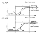
- FIG 10A and FIG. 10B show time charts of change of the operating angle AOP and the assist angle ASP when the select lever 11 is shifted from the P position to the R position, FIG 10A and FIG. 10B showing a normal state and an abnormal state, respectively.
- This select operation by moving the select lever 11 from the P position to the R position is continued for an operating period ⁇ T.
- the drive prohibiting part 34 is shifted to directly output a drive command value signal inputted from the feedback control part 32 to the motor drive control part 35. Accordingly, the control part 35 controls the motor 2 to rotate the second connecting member 17 and follow the first connecting member 13.
- the mode shift unit 500 is operated only by the driver's operating force.
- This operating position select device 1 of the first embodiment has many advantages described below.
- the select lever 11 can be shorter than a conventional one by approximately 150 mm at its portion projecting from a center console toward a passenger compartment without increasing an operating force applied to the select lever 11 so much. This brings a design freedom concerning an installation location of the select lever and/or a layout of a passenger compartment to be broadened.
- This select device 1 is highly robust, because the projection 171 can easily move relative to the wall portions 13a and 13b of the play opening 131 when setting errors, manufacturing errors or age changes occur.
- the mode shift unit 500 can be driven to shift the modes of the automatic transmission 5 by the driver's operating force, although its operating force becomes larger than that in a normal state.
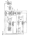
- this operating position select device is constructed similarly to that of the first embodiment shown in FIGS. 1 to 4 except a partial modification of an abnormal diagnosis part 36 in a control unit 3 and use of an inhibitor switch 66.
- the inhibitor switch 66 is mounted on an automatic transmission to detect a selected position A IN of a mode shift unit 500, and outputs a selected position signal.
- the selected position A IN is a selected position angle detected by the inhibitor switch 66 so as to fit its physical quantity to an operating angle A OP of a select lever 11.
- the inhibitor switch 66 acts as a select position sensor of the present invention.
- the abnormal diagnosis part 36 is electrically connected to the inhibitor switch 66 and an operating angle sensor 61 to receive the selected position A IN and the operating angle A OP , and outputs an abnormal diagnosis signal.
- the abnormal diagnosis part 36 judges abnormality of an operating position select device based on a difference between an operating angle A OP and the selected position A IN during rest of an electric motor 2.
- the other parts of the operating position select device of the second embodiment are similar to those of the first embodiment.
- FIG. 12 is a flowchart of assist control process executed by the control unit 3 in order to control the motor 2 when the select lever 11 is operated by a driver.
- the abnormal diagnosis part 36 receives a motor drive signal from a motor drive control part 35 and judges based on it whether or not the motor 2 is actuated. If YES, the flow goes to step S22, while, if NO, it returns.
- the part 36 receives a selected position signal from the inhibitor switch 66 and judges based on it whether or not the automatic transmission is shifted to the P position. If YES, the flow goes to step S25, while, if NO, it goes to step S23.
- the part 36 judges based on the selected position signal whether or not the automatic transmission is shifted to the R position: If YES, the flow goes to step S26, while, if NO, it goes to step S24.
- the part 36 judges based on the selected position signal whether or not the automatic transmission is shifted to the N position. If YES, the flow goes to step S27, while, if NO, it goes to step S28.
- the part 36 receives an operating angle signal from the operating angle sensor 61 and judges based on it whether or not an operating angle AOP is within a range between predetermined values E1 and E2.
- a range between the predetermined values E1 and E2 is a permissible range of the present invention. If YES, the flow returns, while, if NO, it goes to step S29.
- the part 36 judges whether or not the operating angle AOP is within a range between predetermined values E3 and E4.
- a range between the predetermined values E3 and E4 is a permissible range of the present invention. If YES, the flow returns, while, if NO, it goes to step S29.
- the part 36 judges whether or not the operating angle AOP is within a range between predetermined values E5 and E6.
- a range between the predetermined values E5 and E6 is a permissible range of the present invention. If YES, the flow returns, while, if NO, it goes to step S29.
- the part 36 judges whether or not the operating angle AOP is within a range between predetermined values E7 and E8.
- a range between the predetermined values E7 and E8 is a permissible range of the present invention. If YES, the flow returns, while, if NO, it goes to step S29.
- the predetermined values E1 to E8 are set in advance by experiment or computation based on a limit operating angle, which determines the limit angle obtained when the select lever 11 is positioned without problems and errors of the operating angle signal causes no problem after a select operation.
- This limit angle depends on the profile of a check mechanism of a select lever unit, a check pin, and others.
- the part 36 judges whether or not an abnormal state continues for a predetermined period Z2. If YES, the flow goes to step S30, while, if NO, it returns.
- the predetermined period Z2 is set to be any one of 30 seconds to 2 minutes for example in this embodiment.
- the drive prohibiting part 34 receives an abnormal diagnosis signal, indicating abnormality, from the abnormal diagnosis part 36 and prohibits transmittance of a drive command value signal outputted from a feedback control part 32 to the motor drive control part 35. Therefore, assist control is stopped.
- the part 36 determines that the operating position select device has abnormality.
- the manual plate lever is not shifted to a target select position, although the motor 2 drives the manual plate lever toward the target select position. This may cause an improper halt of the select lever 11 between the select portions or wrong operation of the driver, and therefore drive of the motor 2 is stopped.
- the operating position select device of the second embodiment has the following advantages in addition to those of the first embodiment explained above.
- This device can prevent the improper halt of the select lever 11 and the wrong operation of the driver by using the abnormal diagnosis.
- This abnormal diagnosis is executed by using the selected position A IN of the inhibitor switch 66, which comes from the results of the assist control using the motor 2 according to an operation of the select lever 11. Accordingly, this diagnosis can provide an accurate judgment of the abnormality of the operating position select device, since the purpose of the assist control is to adjust control results to the target select position.
- the selected position is detected by the inhibitor switch 66, used in the conventional automatic transmissions, which enables a manufacturing cost of the device to be suppressed.
- this operating position select device is constructed similarly to that of the first embodiment shown in FIGS. 1 to 4 except a partial modification of an abnormal diagnosis part 37 in a control unit 3 and use of an inhibitor switch 66.
- the inhibitor switch 66 is mounted on an automatic transmission to detect a selected position A IN of a mode shift unit 500, corresponding to the assist angle in the first embodiment, and outputs a selected position signal.
- the selected position A IN is a selected position angle detected by the inhibitor switch 66 so as to fit its physical quantity to an assist angle A SP of the mode shift unit 5.
- the inhibitor switch 66 acts as a select position sensor of the present invention.
- the abnormal diagnosis part 37 is electrically connected to the inhibitor switch 66 and an assist angle sensor 62 to receive the selected position A IN and the assist angle A SP , and outputs an abnormal diagnosis signal.
- the abnormal diagnosis part 37 judges abnormality of the operating position select device based on a difference between an assist angle A OP and an selected position A IN during rest of an electric motor 2.
- the other parts of the operating position select device of the third embodiment are similar to those of the first embodiment.
- FIG 14 is a flowchart of an assist control process executed by the control unit 3 in order to control the motor 2 when a select lever 11 is operated by a driver.
- the abnormal diagnosis part 37 receives a motor drive signal from a motor drive control part 35 and judges based on it whether or not the motor 2 is actuated. If YES, the flow goes to step S32, while, if NO, it returns.
- the part 37 receives a selected position signal from the inhibitor switch 66 and judges based on it whether or not the automatic transmission is shifted to the P position. If YES, the flow goes to step S35, while, if NO, it goes to step S33.
- the part 37 judges based on the selected position signal whether or not the automatic transmission is shifted to the R position. If YES, the flow goes to step S36, while, if NO, it goes to step S34.
- the part 37 judges based on the selected position signal whether or not the automatic transmission is shifted to the N position. If YES, the flow goes to step S37, while, if NO, it goes to step S38.
- the part 37 receives an assist angle signal from the assist angle sensor 62 and judges based on it whether or not an assist angle A SP is within a range between predetermined values F 1 and F2.
- a range between the predetermined values F 1 and F2 is a permissible range of the present invention. If YES, the flow returns, while, if NO, it goes to step S39.
- the part 37 judges whether or not the assist angle A OP is within a range between values F3 and F4.
- a range between the predetermined values F3 and F4 is a permissible range of the present invention. If YES, the flow returns, while, if NO, it goes to step S39.
- the part 37 judges whether or not the operating angle A OP is within a range between values F5 and F6.
- a range between the predetermined values F5 and F6 is a permissible range of the present invention. If YES, the flow returns, while, if NO, it goes to step S39.
- the part 37 judges whether or not the operating angle A OP is within a range between values F7 and F8.
- a range between the predetermined values F7 and F8 is a permissible range of the present invention. If YES, the flow returns, while, if NO, it goes to step S39.
- the predetermined values F1 to F8 are set in advance by experiment or computation based on a limit operating angle, which determines the limit angle obtained when the select lever 11 is positioned without problems and errors of the operating angle signal causes no problem after a select operation.
- This limit angle depends on profile of a check mechanism of an select lever unit, a check pin, and others.
- the part 37 judges whether or not an abnormal state continues for the predetermined period Z3. If YES, the flow goes to step S40, while, if NO, it returns.
- the predetermined period Z3 is set to be any one of 30 seconds to 2 minutes for example in this embodiment.
- the drive prohibiting part 34 receives an abnormal diagnosis signal, indicating the abnormality of the device, from the abnormal diagnosis part 37 and prohibits transmittance of a drive command value signal outputted from a feedback control part 32 to the motor drive control part 35. Therefore, assist control is stopped.
- the part 37 determines that the operating position select device has abnormality. In this case, there is a possibility that the manual plate lever is not shifted to a target select position, although the motor 2 drives the manual plate lever toward the target select position. This may cause an improper halt of the select lever 11 between the select portions or wrong operation of the driver, and therefore drive of the motor 2 is stopped.
- the operating position select device of the third embodiment has the following advantages in addition to those of the first embodiment explained above.
- This device can prevent the improper halt of the select lever 11 and the wrong operation of the driver by using the abnormal diagnosis.
- This diagnosis is executed based on the selected position A IN of the inhibitor switch 66, which comes from the results of the assist control using the motor 2 according to an operation of the select lever 11. Accordingly, this diagnosis can provide an accurate judgment, since the purpose of the assist control is to adjust the control results to the target select position.
- the selected position is detected by the inhibitor switch 66, used in the conventional automatic transmissions, which enables a manufacturing cost of the device to be suppressed.
- this operating position select device is constructed similarly to that of the first embodiment shown in FIGS. 1 to 4 except a partial modification of a control unit 3 and use of a relative angle sensor 63 instead of the operating angle sensor and the assist angle sensor.
- the relative angle sensor 63 is arranged at or near a supporting shaft rotatably supporting a first connecting member and a second connecting member to detect a relative angle ⁇ A between these members.
- This sensor 63 is constructed as follows. For example, on a surface of the first connecting member, an electric terminal is fixed, and on its facing face of the second connecting member, a carbon resistor printed on a substrate is fixed. The electric terminal is movable around the supporting shaft together with the first connecting member to change its angle with respect to the carbon resistor of the second rotatble member. This angle change causes a change of resistance value, and consequently electric current flowing them changes. This current is used as a relative angle signal. The electric terminal and the carbon resister may be replaced with each other.
- the relative angle sensor 63 acts as a relative displacement sensor of the present invention, and the relative angle ⁇ A corresponds a relative displacement of the present invention.
- the control unit 3 includes a drive command value calculating part 31', a drive prohibiting part 34, a motor drive control part 35, and an abnormal relative displacement detecting part 36.
- the drive command value calculating part 31' is electrically connected to the relative angle sensors 63 to receive a relative angle ⁇ A, and calculates a drive command value based on it, outputting a drive command value signal.
- the drive command value calculating part 31' acts as a drive command value calculating means of the present invention.
- the abnormal relative displacement detecting part 36 is electrically connected to the relative angle sensors 63 to receive the relative angle ⁇ A, and judges abnormality of the select device, outputting an abnormal state judgment signal.
- the abnormal relative displacement detecting part 36 includes a relative displacement state detecting part 331, a timer 332, a memory 333, and a comparator 334.
- the relative displacement state detecting part 331 is electrically connected to the relative angle sensor 63 to receive the relative angle ⁇ A. Then, it judges a displacement state whether or not the relative angle ⁇ A is within a permissible range limited by a relatively movable amount between a first connecting member and a second connecting member, such as a travelable amount of a projection fixed on the second connecting member in a play opening formed in the first connecting member.
- the timer 332 is electrically connected to the relative displacement state detecting part 331 and starts to count up elapsed time when it receives a signal from the state detecting part 331 indicating that the relative angle ⁇ AP is out of the permissible range.
- the timer 332 clears the elapsed time when it receives a signal indicating that the relative angle ⁇ A is within the permissible range.
- the memory 333 stores a predetermined period as a predetermined period TK for judging abnormality of the select device.
- the predetermined period TK is set, for example any one of 30 seconds to 2 minutes, allowing for drive current application time to shift the select lever to an adjacent select position at the maximum current level, which is obtained in a case where the relative angle ⁇ A is out of the permissible range, since drive current becomes larger in proportion to the relative angle ⁇ A.
- the comparator 334 is electrically connected to the timer 332 and the memory 333 and compares the elapsed time to the predetermined period TK. When it judges that the elapsed time is within the predetermined period TK, it outputs an abnormal state judgment signal for allowing the drive command value signal to pass therethrough, while, when it judges that the elapsed time is out of the predetermined period TK, it outputs the abnormal state judgment signal for prohibiting passing-through of the signal.
- the drive prohibiting part 34 is electrically connected to the calculating part 31' and the comparator 334 of the detecting part 36 to receive the drive command value signal and the abnormal state judgment signal to control an output of the drive command value signal. Specifically, when the received judgment signal indicates abnormality, the prohibiting part 34 outputs the drive command value signal, indicating drive command value of zero, to stop the motor 2, while, when the signal indicates a normal state, it outputs directly the drive command value signal inputted from the calculating part 31' to drive the motor 2.
- the drive prohibiting part 34 acts as a drive prohibiting part of the present invention.
- the motor drive control part 35 is electrically connected to the drive prohibiting part 34 to receive the drive command value signal. When it receives the signal, it supplies the motor 2 with drive current determined based on the signal under PWM control to the motor 2.
- the other parts of the operating position select device of the fourth embodiment are similar to those of the first embodiment.
- the assist control is executed as follows according to a flowchart similar to that of the first embodiment shown in FIG 5 .
- a relative angle ⁇ A is used instead of the operating angle and the assist angle in the first embodiment.
- the drive command value calculating part 31' receives a relative angle ⁇ A to determine a motor command value based on the relative angle ⁇ A.
- the motor drive control part 35 receives the motor command value and outputs a motor drive electric current determined based on the value to the motor 2.
- FIG 17 is a flowchart of an abnormal diagnosis process executed in the control unit 3.
- step 41 the drive command value calculating part 31' and the abnormal relative displacement detecting part 36 read a relative angle ⁇ AP, and then the flow goes to step S42.
- the calculating part 31' calculates a motor command value based on the relative angle ⁇ A, and then the flow goes to step S43.
- the calculating part 31' calculates a duty ratio RD as the motor command value for controlling the motor 2 under PWM drive by using Proportional-Integral-Derivative (PID) control.
- PID Proportional-Integral-Derivative
- the relative displacement state detecting part 331 of the detecting part 36 judges whether or not the relative angle ⁇ A is within a permissible range B.
- the permissible range B is set similarly to that of the second and third embodiments. If YES, the flow goes to step S44, while, if NO, it goes to step S45.
- step S 44 the timer 332 clears elapsed time T, and then the flow goes to step S46.
- the timer 332 starts to count up the elapsed time T, and then the flow goes to the step S46.
- the comparator 334 judges whether or not the elapsed time T is equal to or larger than the predetermined period TK. If YES, the flow goes to step S47, while, if NO, it goes to step S48.
- the drive prohibiting part 34 outputs the drive command value signal set to be zero, and then the flow ends.
- the drive prohibiting part 34 outputs directly the drive command value signal inputted from the calculating part 31', and then the flow ends.
- the abnormality may occur due to the following reasons.
- the first reason is abnormality of the relative angle sensor 63, which outputs a wrong relative angle signal indicating an angle out of the permissible range, although it is actually within the permissible range.
- the timer 332 starts to count up an elapsed time T according to the steps S42 and S45, and when the elapsed time T is counted up to the predetermined period TK, the drive command value is set to be zero by the drive prohibiting part 34 to stop the motor 2. This brings the projection and the wall portion of the play opening to be in contact with each other, mechanically transmitting operating force inputted from the select lever 11 to the mode shift unit through a control cable, but its operating force needs to be larger to move the lever 11.
- the drive prohibiting part 34 prevents the motor 2 from being driven before a shift to the adjacent select position has completed, avoiding unintentional mode-shifting of the automatic trans mission.
- the steps S 13 and S 15 are executed during its initial phase, so that the timer 332 starts to count up the elapsed time T, but when a detected relative angle ⁇ A returns to a normal value before the elapsed time T reaches the predetermined period TK, the flow goes to the steps S 13 and S14 to clear the elapsed time T and permit drive of the motor 2.
- the drive of the motor 2 is prohibited when the noise affecting on an overrun of the select lever 11 occurs, while it is permitted when noise occurs and immediately reduces to the amount free from the overrun or when the noise does not occur.
- the operating position select device of the fourth embodiment has the following advantages in addition to those of the first embodiment.
- the abnormal relative displacement detecting part 36 can distinguish an instantaneous abnormality due to such as noise from not-instantaneous abnormality. Therefore, drive or stop of the motor 2 is controllable optimally according to level of affection of the abnormality detected.
- this operating position select device is constructed similarly to that of the first embodiment shown in FIGS. 1 to 4 except a modification of a control unit 3 and use of a first relative angle sensor 64 and a second relative angle sensor 65, instead of the relative angle sensor.
- the control unit includes a relative displacement average value calculating part 37, a drive command value calculating part 3 1 ", an abnormal relative displacement detecting part 36, a drive prohibiting part 34, and a motor drive control part 35.
- the first relative angle sensor 64 is arranged at or near a supporting shaft rotatably supporting a first connecting member and a second connecting member to detect a first relative angle ⁇ A1 between these members and output a first relative angle signal.
- This sensor 64 is constructed as follows. For example, on a surface of the first connecting member, an electric terminal is fixed, and on its facing face of the second connecting member, a carbon resistor printed on a substrate is fixed. The electric terminal is movable around the supporting shaft together with the first connecting member to change its angle with respect to the carbon resistor of the second rotatble member. This angle change causes a change of resistance value, and consequently electric current flowing in them changes. This current corresponds to the first relative angle signal.
- the electric terminal and the carbon resister may be replaced with each other.
- the first relative angle sensor 64 acts as a relative position sensor of the present invention.
- the second relative angle sensor 65 is also arranged at or near the supporting shaft to detect a second relative angle ⁇ A2 between these members and output a second relative angle signal.
- This sensor 65 employs, for example, the same type of the first relative angle sensor 64.
- the second relative angle sensor 65 acts as the relative position sensor of the present invention, and the second relative angle signal corresponds to the relative position signal of the present invention.
- the first and second relative sensors 64 and 65 may use another type, for example, a rotary encorder using a light emitting element, a light-sensitive element, and a disc with slits located between them.
- the elements are fixed on one of the first and second connecting members, and the disc is fixed to the other of the members.
- the light-sensitive elements receives light emitted from the light emitting element and passing through the slits of the disc, which can provide an electric current, corresponding to the second relative angle signal.
- the first and second relative angle sensors 64 and 65 may use a different type from each other.
- the relative displacement average value calculating part 37 is electrically connected to the first relative angle sensor 64 and the second relative angle sensor 65 to receive the first relative angle signal and the second relative angle signal to calculate a relative displacement average value of them and output a relative displacement average value signal.
- the drive command value calculating part 31 " is electrically connected to the average value calculating part 37 to receive the relative displacement average value signal and calculate a drive command value, outputting a drive command value signal.
- the drive command value calculating part 31" acts as a drive command value calculating means of the present invention.
- the abnormal relative displacement detecting part 36 is electrically connected to the first relative angle sensor 64 and the second relative angle sensor 65 to receive the first relative angle signal and the second relative angle signal, and judges abnormality of the select device, outputting an abnormal state judgment signal.
- the detecting part 36 has a relative displacement variation calculating part 361, a first memory 362, a first comparator 363, a timer 364, a second memory 365, and a second comparator 366.
- the relative displacement variation calculating part 361 is electrically connected to the first relative angle sensor 64 and the second relative angle sensor 65 to receive the first relative angle signal and the second relative angle signal, and calculates a variation ⁇ DA between the first and second relative angles ⁇ A1 and ⁇ A2, outputting a variation signal.
- the first memory 362 stores a limit value AK of a permissible range, which is an allowable value of a variation between the first and second relative angles.
- the first comparator 363 is electrically connected to the calculating part 361 and the first memory 362 to receive the variation signal and the limit value AK.
- the compressor 363 compares them to output a timer start signal so that it may start the timer 364 to count up an elapsed time when the variation ⁇ DA is equal to or larger than the limit value AK, while it may clear the timer 364 when the variation ⁇ DA is less than the limit value AK.
- the timer 364 is electrically connected to the first comparator 363 to receive the timer start signal and start to count up an elapsed time when it receives the timer start signal.
- the second memory 365 stores a predetermined period TK for judging abnormality of the select device.
- the predetermined period TK is set allowing for drive current application time to shift the select lever to an adjacent select position at the maximum current level.
- the comparator 366 is electrically connected to the timer 364 and the second memory 365 and compares the elapsed time to the predetermined period TK. When it judges that the elapsed time is within the predetermined period TK, it outputs an abnormal state judgment signal for allowing a drive command value signal outputted by a drive command value calculating part 31" to pass therethrough, while, when it judges that the elapsed time is equal to or larger than the predetermined period TK, it outputs the abnormal state judgment signal for prohibiting passing-through of the signal.
- the other parts of the operating position select device of the fifth embodiment are similar to those of the first and fourth embodiments.
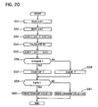
- FIG. 20 is a flowchart of an abnormal diagnosis process executed by the control unit 3 in order to control the motor 2 when a select lever 11 is operated by a driver.
- the relative displacement average value calculating part 37 receives a first relative angle signal from the first relative angle sensor 64, and then the flow goes to step S52.
- the average value calculating part 37 also receives a second relative angle signal from the second relative angle sensor 65, and then the flow goes to step 53.
- the average value calculating part 37 calculates a relative displacement average value ⁇ AA by using an equation of ( ⁇ A1 + ⁇ A2) / 2 based on a first relative angle ⁇ A1 and a second relative angle ⁇ A2, and then the flow goes to step S54.
- the drive command value calculating part 31" receives the average value ⁇ AA to calculate a duty ratio RD as a drive command value, and then the flow goes to step S55.
- the first comparator 363 compares the numerical value ⁇ DA of the variation and the limit value AK to judge whether or not the numerical value ⁇ DA is equal to or larger than the limit value AK. If YES, the flow goes to step S57, while, if NO, it goes to step S58.
- step S57 the timer 364 starts to count up an elapsed time T, and then the flow goes to step S59.
- the timer 364 clears the elapsed time T, and then the flow goes to the step S59.
- the second comparator 363 compares the elapsed time T and the predetermined period TK to judge whether or not the elapsed time T is equal to or larger than the predetermined period TK. If YES, the flow goes to step S60, while, if NO, it goes to step S61.
- the drive prohibiting part 34 outputs the drive command value signal set to be zero, and then the flow ends.
- the drive prohibiting part 34 outputs directly the drive command value signal inputted from the calculating part 31 ", and then the flow ends.
- a high level of confidence in measurement of the relative displacement between the first and second connecting members can be obtained by using two relative angle sensors 64 and 65 and calculating their average value.
- abnormality can be detected when their variation becomes larger than a predetermined value that is not detected in normal states of them.
- both the sensors 64 and 65 hardly ever become an abnormal state similar to each other. Accordingly, the instantaneous abnormality can be distinguished from other type abnormality based on duration of their abnormal variation.
- the abnormal variation is instantaneously short, it is due to the noise or the like, while when the variation continues for more than a certain amount of time.
- the operating position select device of the fifth embodiment has the following advantages in addition to those of the first and fifth embodiments.
- this device has two relative displacement sensor 64 and 65, level of confidence for detecting a relative displacement can be increased.
- the relative displacement can be surely detected when one of the sensors 64 and 65 fails.
- an electric motor 2 and a second connecting member 17 are mounted on an automatic transmission 5.
- this operating position select device is constructed similarly to that of the first embodiment shown in FIGS. 1 to 4 except the following elements.
- a first connecting member 13 is integrally joined with a select lever 11 of a select lever unit 100 and provided with a play opening 131.
- the second connecting member 17 is mounted on the automatic transmission 5 and has a worm wheel portion 16 in mesh with a worm 21 connected on an output shaft of an electric motor 2 mounted on the automatic transmission 5.
- This member 17 is integrally formed with a manual plate member 18 at its end portion.
- a control cable 4 has a projection 171 inserted into the play opening 131 with clearances therebetween at its one end portion and is connected with the second connecting member 17 at its other end portion.
- the other parts of the operating position select device of the sixth embodiment are similar to those of the first to fifth embodiments.
- select device 1 of the sixth embodiment is similar to those of the first to fifth embodiments. Further, the select lever unit 100 can be smaller than those of the embodiments, since the second connecting member 17 and the motor 2 are mounted on the automatic transmission 5.
- the relative displacement is detected by a length, not by an angle in the fourth embodiment, and at a position between a first control cable 8a and a second control cable 8b which connect a select lever 11 with an actuator 9.
- FIG 22 of the drawing there is shown an automatic transmission 5 and an operating position select device 1 to control the transmission 5.
- the operating position select device 1 includes a select lever unit 100 manually operated by a driver, a mode shift unit 500 mounted on the automatic transmission 5, a first control cables 8a, a second control cable 8b, and a third control cable 8e for transmitting operating force from the select lever 11 to the mode shift unit 500, the assist actuator 9, and a control unit 3 for controlling the assist actuator 9.
- the select lever unit 100 is arranged, for example, at a center console 3 beside a driver's seat and has the select lever 11 operated by the driver and a checking mechanism 14 for ensuring the select lever 11 to be kept in a selected mode position.
- the assist actuator 9 includes an electric motor 2 with reduction gears for reducing rotation speed of its output shaft, a worm 97 formed on the output shaft, and a worm wheel 93 meshing with the worm 97 and integrally united to a coupling shaft 94.
- the coupling shaft 94 is integrally provided with the worm wheel 93 at its intermediate portion, a first plate 92 at its top end portion, and a second plate 95 at its bottom end portion.
- the first control cable 8a is connected with a bottom portion of the select lever at its one end portion and a piston 8c at its other end portion.
- the second control cable 8b is connected with a cylinder 8d at its one end portion and the first plate 92 by a first pin 91 at its other end portion.
- the piston 8c is disposed slidably in the cylinder 8d to have clearances between wall portions of the cylinder 8d, so that the first control cable 8a can move relative to the second control cable 8b in a permissible range, where the piston 8c is not in contact with the wall portions of the cylinder 8d.
- the first and second control cables 8a and 8b moves together with each other to transmit operating force therebetween when the piston 8c is in contact with the wall portion of the cylinder 8d.
- the third control cable 8e is connected with the second plate 95 by a second pin 96 at its one end portion and a manual plate lever 51 at its other end portion.
- a relative displacement sensor 71 for detecting a relative displacement between the piston 8c and a middle point of the inside of the cylinder 8d.
- select device 1 of the seventh embodiment is similar to those of the first to fifth embodiments. Further, the select lever unit 100 can be smaller than those of the embodiments, since the second connecting member 17 and the motor 2 are disposed between the select lever unit 100 and the automatic transmission 5.
- the first and second connecting members 13 and 17 may be located at a select lever unit, an automatic transmission, or an intermediate position between them.
- the select lever 2 may be in a shape different from the above embodiments, and have a configuration different from that of the first embodiment shown in FIGS. 1 and 2 , for example, a finger- controable one.
- the configuration of the cam 530 of the detent mechanism 510 may be formed arbitrarily to have different target reaction force.
Landscapes
- Engineering & Computer Science (AREA)
- General Engineering & Computer Science (AREA)
- Mechanical Engineering (AREA)
- Gear-Shifting Mechanisms (AREA)
- Arrangement Or Mounting Of Control Devices For Change-Speed Gearing (AREA)
Claims (7)
- Dispositif de sélection de position d'opération (1) pour une transmission automatique (5) dont les modes d'opération peuvent être changés, comportant:une unité de levier de sélection (100) présentant un levier de sélection (11) qui est actionné par un conducteur entre une pluralité de positions de sélection correspondant aux modes d'opération ;un premier élément de connexion (13) relié mécaniquement à et déplaçable avec le levier de sélection (11) ;un capteur de position d'opération (61) détectant une position d'opération du levier de sélection (11) ;une unité de changement de modes (500) montée sur la transmission automatique (5) pour changer les modes d'opération de la transmission automatique (5) ;un second élément de connexion (17) relié mécaniquement à l'unité de changement de modes (500) pour changer les positions de celle-ci ;un capteur d'assistance (62) détectant une position d'assistance de l'unité de changement de modes (500);un actionneur d'assistance (2, 9) délivrant une force d'assistance à l'unité de changement de modes (500);
et caractérisé parle second élément de connexion (17) déplaçable relativement par rapport au premier élément de connexion (13) jusqu'à une valeur limite et déplaçable avec le premier élément de connexion (13) au-delà de la valeur limite comme un tout;un moyen de calcul de valeur de commande d'entraînement (32, 31', 31") calculant une valeur de commande d'entraînement pour entraîner l'actionneur d'assistance (2, 9) en fonction de la position d'opération et de la position d'assistance de sorte qu'une différence entre la position d'opération et la position d'assistance peut être réduite ;un moyen d'empêchement d'entraînement (34) pour empêcher l'entraînement de l'actionneur d'assistance lorsque la différence est maintenue hors d'une plage autorisée pour une période prédéterminée pendant le repos de l'actionneur d'assistance. - Dispositif de sélection de position d'opération (1) pour une transmission automatique (5) selon la revendication 1, caractérisé en ce quel'un des éléments constitués par le premier élément de connexion (13) et le second élément de connexion (17) est muni d'une partie saillante (171) et l'autre des éléments constitués par le premier élément de connexion (13) et le second élément de connexion (17) est formé avec une ouverture de jeu (131) dans laquelle la partie saillante (171) est insérée, et dans lequell'ouverture de jeu (131) est définie par deux parties de paroi (13a, 13b) disposées éloignées dans une direction de déplacement du levier de sélection (11), de sorte que la partie saillante (171) est éloignée des parties de paroi (13a, 13b) dans une opération de sélection normale et vient au contact de l'une des parties de paroi (13a, 13b) pour transmettre une force d'opération depuis le levier de sélection (11) à l'unité de changement de mode (500) dans une opération de sélection anormale.
- Dispositif de sélection de position d'opération (1) pour une transmission automatique (5) dont les modes d'opération peuvent être changés, comportant:une unité de levier de sélection (100) présentant un levier de sélection qui est actionné par un conducteur entre une pluralité de positions de sélection correspondant aux modes d'opération ;un premier élément de connexion (13) mécaniquement relié à et déplaçable avec le levier de sélection (11) ;un capteur de position d'opération (61) détectant une position d'opération du levier de sélection (11) ;une unité de changement de mode (500) montée sur la transmission automatique (5) pour changer les modes d'opération de la transmission automatique (5) ;un second élément de connexion (17) relié mécaniquement à l'unité de changement de mode (500) pour changer les positions de celle-ci ;un capteur de position d'assistance (62) détectant une position d'assistance de l'unité de changement de mode (500) ;un capteur de position d'opération changée (66) détectant une position d'opération changée de la transmission automatique (5) ;un actionneur d'assistance (2, 9) délivrant une force d'assistance à l'unité de changement de mode (500) ;
et caractérisé parle second élément de connexion (17) déplaçable par rapport au premier élément de connexion (13) jusqu'à une valeur limite relativement et déplaçable avec le premier élément de connexion (13) au-delà de la valeur limite comme un tout ;un moyen de calcul de valeur de commande d'entraînement (32, 31', 31") calculant une valeur de commande d'entraînement pour entraîner l'actionneur d'assistance (2, 9) en fonction de la position d'opération et de la position d'assistance de sorte qu'une différence entre la position d'opération et la position d'assistance peut être réduite ; etun moyen empêchant l'entraînement (34) pour empêcher l'entraînement de l'actionneur d'assistance (2, 9) lorsqu'une différence entre la position d'opération changée et une position choisie entre la position d'opération et la position d'assistance est maintenue hors d'une plage autorisée pour une période prédéterminée pendant le repos de l'actionneur d'assistance (2, 9). - Dispositif de sélection de position d'opération (1) pour une transmission automatique (5) selon la revendication 3, caractérisé en ce quel'un des éléments constitués par le premier élément de connexion (13) et le second élément de connexion (17) est muni d'une partie saillante (171) et l'autre des éléments constitués par le premier élément de connexion (13) et le second élément de connexion (17) est formé avec une ouverture de jeu (131) dans laquelle la partie saillante (171) est insérée, et dans lequell'ouverture de jeu (131) est définie par deux parties de paroi (13a, 13b) disposées éloignées dans une direction de déplacement du levier de sélection (11) de sorte que la partie saillante (171) est éloignée des parties de paroi (13a, 13b) dans une opération de sélection normale et vient au contact d'une des parties de paroi (13a, 13b) pour transmettre une force d'opération du levier de sélection (11) à l'unité de changement de mode (500) dans une opération de sélection anormale.
- Dispositif de sélection de position d'opération (1) pour une transmission automatique (5) selon l'une des revendications 3 ou 4, caractérisé en ce quele capteur de position d'opération changée est un commutateur inhibiteur (66) de la transmission automatique (5).
- Dispositif de sélection de position d'opération (1) pour une transmission automatique (5) dont les modes d'opération peuvent être changés, comportant :une unité de levier de sélection (100) possédant un levier de sélection (11) qui est actionné par un conducteur entre une pluralité de positions de sélection correspondant aux modes d'opération ;un premier élément de connexion (13) relié mécaniquement à et déplaçable avec le levier de sélection (11) ;une unité de changement de mode (500) monté sur la transmission automatique (5) pour changer les modes d'opération de la transmission automatique (5) ;un second élément de connexion (17) relié mécaniquement à l'unité de changement de mode (500) pour changer les positions de celles-ci;un capteur de déplacement relatif (63, 64, 65) détectant un déplacement relatif entre le premier élément de connexion (13) et le second élément de connexion (17) ;un actionneur d'assistance (2, 9) disposé entre le levier de sélection (11) et l'unité de changement de mode (500) et délivrant une force d'assistance à l'unité de changement de mode (500) ;
et caractérisé parle second élément de connexion (17) déplaçable par rapport au premier élément de connexion (13) jusqu'à une valeur limite relativement et déplaçable avec le premier élément de connexion (13) au-delà d'une valeur limite comme un tout;un moyen de calcul de valeur de commande d'entraînement (32, 31', 31") calculant une valeur de commande d'entraînement pour entraîner l'actionneur d'assistance (2, 9) en fonction du déplacement relatif de sorte que le déplacement relatif peut être réduit ; etun moyen d'empêchement d'entraînement (34) pour empêcher l'entraînement de l'actionneur d'assistance (2, 9) lorsque le déplacement relatif est maintenu hors d'une plage autorisée pour une période prédéterminée pendant le repos de l'actionneur d'assistance (2, 9). - Dispositif de sélection de position d'opération (1) pour une transmission automatique (5) selon la revendication 6, caractérisé en ce quel'un des éléments constitués par le premier élément de connexion (13) et le second élément de connexion (17) est muni d'une partie saillante (171) et l'autre des éléments constitués par le premier élément de connexion (13) et le second élément de connexion (17) est formé avec une ouverture de jeu (131) dans laquelle la partie saillante (171) est insérée, et dans lequell'ouverture de jeu (131) est définie par deux parties de paroi (13a, 13b) disposées éloignées dans une direction de déplacement du levier de sélection (1) de sorte que la partie saillante (171) est éloignée des parties de paroi (13a, 13b) dans une opération de sélection normale et vient au contact de l'une des parties de paroi (13a, 13b) pour transmettre une force d'opération depuis le levier de sélection (11) à l'unité de changement de mode (500) dans une opération de sélection anormale.
Applications Claiming Priority (2)
| Application Number | Priority Date | Filing Date | Title |
|---|---|---|---|
| JP2004301826A JP2006112552A (ja) | 2004-10-15 | 2004-10-15 | 自動変速機のセレクトアシスト装置 |
| JP2005016080A JP2006200722A (ja) | 2005-01-24 | 2005-01-24 | 自動変速機のセレクトアシスト装置 |
Publications (2)
| Publication Number | Publication Date |
|---|---|
| EP1647743A1 EP1647743A1 (fr) | 2006-04-19 |
| EP1647743B1 true EP1647743B1 (fr) | 2008-04-16 |
Family
ID=35601817
Family Applications (1)
| Application Number | Title | Priority Date | Filing Date |
|---|---|---|---|
| EP05292165A Expired - Fee Related EP1647743B1 (fr) | 2004-10-15 | 2005-10-14 | Dispositif de sélection de position d'opération pour une transmission automatique |
Country Status (3)
| Country | Link |
|---|---|
| US (1) | US7313980B2 (fr) |
| EP (1) | EP1647743B1 (fr) |
| DE (1) | DE602005006067T2 (fr) |
Families Citing this family (21)
| Publication number | Priority date | Publication date | Assignee | Title |
|---|---|---|---|---|
| US7426881B2 (en) * | 2003-10-29 | 2008-09-23 | Calsonic Kansei Corporation | Operating position select device for automatic transmission |
| JP2006125545A (ja) * | 2004-10-29 | 2006-05-18 | Calsonic Kansei Corp | 自動変速機のセレクトアシスト装置 |
| JP2007085411A (ja) * | 2005-09-21 | 2007-04-05 | Calsonic Kansei Corp | 自動変速機のセレクトアシスト装置 |
| JP2007147023A (ja) * | 2005-11-30 | 2007-06-14 | Calsonic Kansei Corp | 自動変速機のセレクトアシスト装置 |
| DE102007024030B4 (de) | 2007-05-22 | 2011-01-05 | Zf Friedrichshafen Ag | Betätigungseinrichtung mit Sperrvorrichtung |
| US9043100B2 (en) | 2007-08-17 | 2015-05-26 | Steering Solutions Ip Holding Corporation | Transmission shift assembly for a vehicle and a method of monitoring the same |
| US8893571B2 (en) * | 2007-08-17 | 2014-11-25 | Steering Solutions Ip Holding Corporation | Transmission shift assembly for a vehicle and a method of monitoring the same |
| JP4952932B2 (ja) * | 2007-09-05 | 2012-06-13 | 三菱自動車工業株式会社 | トランスミッション用スイッチ装置及びこれを用いたトランスミッション |
| JP5463620B2 (ja) * | 2008-02-26 | 2014-04-09 | 日産自動車株式会社 | 自動変速機搭載車のシフトバイワイヤ故障時制御装置 |
| JP5131066B2 (ja) * | 2008-07-15 | 2013-01-30 | トヨタ自動車株式会社 | 車両の制御装置 |
| JP4672066B2 (ja) * | 2009-03-18 | 2011-04-20 | 三菱電機株式会社 | 自動変速機の制御装置 |
| US8560193B2 (en) * | 2010-03-15 | 2013-10-15 | Ford Global Technologies, Llc | Range shifting of an automatic transmission |
| US8634995B2 (en) * | 2011-12-09 | 2014-01-21 | Ford Global Technologies, Llc | Method and system for providing a voting strategy for determining a mode state in a shift-by-wire transmission |
| US20130269467A1 (en) * | 2012-04-17 | 2013-10-17 | John R. Rice | Power actuator with integral decoupling mechanism |
| EP2711797A1 (fr) * | 2012-09-21 | 2014-03-26 | ABB Research Ltd. | Fonctionnement d'un contrôleur logique programmable |
| US9759313B2 (en) | 2014-11-26 | 2017-09-12 | Polaris Industries Inc. | Electronic shifting of a transmission |
| CN107005195B (zh) * | 2014-11-26 | 2019-03-01 | 日产自动车株式会社 | 电动机的控制装置以及控制方法 |
| US9746070B2 (en) * | 2014-11-26 | 2017-08-29 | Polaris Industries Inc. | Electronic control of a transmission |
| JP6575336B2 (ja) * | 2015-12-07 | 2019-09-18 | 株式会社デンソー | 自動変速機用油圧制御システムの制御装置 |
| CN107989989A (zh) * | 2017-11-02 | 2018-05-04 | 中国第汽车股份有限公司 | 一种气助力式手动换档机构 |
| JP7216626B2 (ja) * | 2019-09-05 | 2023-02-01 | カワサキモータース株式会社 | 変速機付き車両 |
Family Cites Families (9)
| Publication number | Priority date | Publication date | Assignee | Title |
|---|---|---|---|---|
| JPS60256649A (ja) | 1984-06-04 | 1985-12-18 | Jidosha Kiki Co Ltd | 変速機操作用倍力装置 |
| JPH0587237A (ja) | 1991-09-27 | 1993-04-06 | Fuji Univance:Kk | 操作力軽減装置 |
| JPH09323559A (ja) | 1996-06-05 | 1997-12-16 | Nissan Motor Co Ltd | 自動変速機の操作装置 |
| JP2001235028A (ja) * | 2000-02-23 | 2001-08-31 | Isuzu Motors Ltd | 変速機のシフトアシスト装置 |
| JP4183111B2 (ja) | 2001-09-27 | 2008-11-19 | ジヤトコ株式会社 | シフトバイワイヤシステム |
| DE602004001880T2 (de) | 2003-01-07 | 2007-04-05 | Calsonic Kansei Corp. | Wählhebel für Automatikgetriebe |
| US7194927B2 (en) * | 2003-09-17 | 2007-03-27 | Calsonic Kansei Corporation | Operating position select device for automatic transmission |
| JP2005106100A (ja) | 2003-09-29 | 2005-04-21 | Calsonic Kansei Corp | 自動変速機のセレクトアシスト装置 |
| JP2006029419A (ja) * | 2004-07-14 | 2006-02-02 | Calsonic Kansei Corp | 自動変速機のセレクトアシスト装置 |
-
2005
- 2005-10-13 US US11/248,609 patent/US7313980B2/en not_active Expired - Fee Related
- 2005-10-14 EP EP05292165A patent/EP1647743B1/fr not_active Expired - Fee Related
- 2005-10-14 DE DE602005006067T patent/DE602005006067T2/de not_active Expired - Lifetime
Also Published As
| Publication number | Publication date |
|---|---|
| EP1647743A1 (fr) | 2006-04-19 |
| US7313980B2 (en) | 2008-01-01 |
| DE602005006067T2 (de) | 2009-05-07 |
| US20060081085A1 (en) | 2006-04-20 |
| DE602005006067D1 (de) | 2008-05-29 |
Similar Documents
| Publication | Publication Date | Title |
|---|---|---|
| EP1647743B1 (fr) | Dispositif de sélection de position d'opération pour une transmission automatique | |
| EP1437533B1 (fr) | Levier de selection pour boîte de vitesses automatique | |
| EP0959271B1 (fr) | Actionneur hélicoidal de câble de changement de vitesse | |
| US7426881B2 (en) | Operating position select device for automatic transmission | |
| EP1528296B1 (fr) | Dispositif de sélection de position d'opération pour une transmission automatique | |
| US6877390B2 (en) | Shift range changeover mechanism | |
| EP1517069B1 (fr) | Dispositif de sélection de position d'opération pour une transmission automatique. | |
| EP1617107A2 (fr) | Dispositif de sélection du mode de fonctionnement pour transmission automatique | |
| EP1653125A2 (fr) | Dispositif de sélection de position d'opération pour une transmission automatique | |
| EP1519083A1 (fr) | Dispositif de sélection de position d'opération pour une transmission automatique. | |
| EP1598577A2 (fr) | Dispositif de sélection de position d'opération pour une transmission automatique | |
| EP1561973B1 (fr) | Levier de commande avec connection mécanique à la transmission avec assistance servo | |
| EP1591697A2 (fr) | Dispositif de sélection de position d'opération pour une transmission automatique | |
| US9043100B2 (en) | Transmission shift assembly for a vehicle and a method of monitoring the same | |
| EP1767830A1 (fr) | Dispositif de sélection de position d'opération pour une transmission automatique | |
| US6289756B1 (en) | Electronic shifter assembly with positioning mechanism to aid in setting shift lever to desired gear setting | |
| EP1355091B1 (fr) | Dispositif de commande de transmission robotisée, à fonction d'apprentissage pour les positions de rapports | |
| JP2883350B2 (ja) | 自動変速機の操作装置 | |
| US20090082932A1 (en) | Select Assist Device for Automatic Transmission | |
| HK1060169B (en) | A control system for a robotized gearbox in a motor vehicle, with the ability to learn the position of the ratios or gears |
Legal Events
| Date | Code | Title | Description |
|---|---|---|---|
| PUAI | Public reference made under article 153(3) epc to a published international application that has entered the european phase |
Free format text: ORIGINAL CODE: 0009012 |
|
| AK | Designated contracting states |
Kind code of ref document: A1 Designated state(s): AT BE BG CH CY CZ DE DK EE ES FI FR GB GR HU IE IS IT LI LT LU LV MC NL PL PT RO SE SI SK TR |
|
| AX | Request for extension of the european patent |
Extension state: AL BA HR MK YU |
|
| 17P | Request for examination filed |
Effective date: 20060608 |
|
| AKX | Designation fees paid |
Designated state(s): DE FR GB |
|
| GRAP | Despatch of communication of intention to grant a patent |
Free format text: ORIGINAL CODE: EPIDOSNIGR1 |
|
| GRAS | Grant fee paid |
Free format text: ORIGINAL CODE: EPIDOSNIGR3 |
|
| GRAA | (expected) grant |
Free format text: ORIGINAL CODE: 0009210 |
|
| AK | Designated contracting states |
Kind code of ref document: B1 Designated state(s): DE FR GB |
|
| RIN1 | Information on inventor provided before grant (corrected) |
Inventor name: OTSUKA, TAKASHIC/O CALSONIC KANSEI CORPORATION Inventor name: OSAMURA, KENSUKEC/O CALSONIC KANSEI CORPORATION Inventor name: KOBAYASHI, SHINYAC/O CALSONIC KANSEI CORPORATION Inventor name: NAGANO, MASAHARUC/O CALSONIC KANSEI CORPORATION Inventor name: HIROTA, YUKITSUGUC/O CALSONIC KANSEI CORPORATION |
|
| REF | Corresponds to: |
Ref document number: 602005006067 Country of ref document: DE Date of ref document: 20080529 Kind code of ref document: P |
|
| ET | Fr: translation filed | ||
| PLBE | No opposition filed within time limit |
Free format text: ORIGINAL CODE: 0009261 |
|
| STAA | Information on the status of an ep patent application or granted ep patent |
Free format text: STATUS: NO OPPOSITION FILED WITHIN TIME LIMIT |
|
| 26N | No opposition filed |
Effective date: 20090119 |
|
| PGFP | Annual fee paid to national office [announced via postgrant information from national office to epo] |
Ref country code: DE Payment date: 20091008 Year of fee payment: 5 |
|
| PGFP | Annual fee paid to national office [announced via postgrant information from national office to epo] |
Ref country code: FR Payment date: 20091029 Year of fee payment: 5 Ref country code: GB Payment date: 20091014 Year of fee payment: 5 |
|
| GBPC | Gb: european patent ceased through non-payment of renewal fee |
Effective date: 20101014 |
|
| PG25 | Lapsed in a contracting state [announced via postgrant information from national office to epo] |
Ref country code: FR Free format text: LAPSE BECAUSE OF NON-PAYMENT OF DUE FEES Effective date: 20101102 |
|
| REG | Reference to a national code |
Ref country code: FR Ref legal event code: ST Effective date: 20110630 |
|
| PG25 | Lapsed in a contracting state [announced via postgrant information from national office to epo] |
Ref country code: GB Free format text: LAPSE BECAUSE OF NON-PAYMENT OF DUE FEES Effective date: 20101014 |
|
| REG | Reference to a national code |
Ref country code: DE Ref legal event code: R119 Ref document number: 602005006067 Country of ref document: DE Effective date: 20110502 |
|
| PG25 | Lapsed in a contracting state [announced via postgrant information from national office to epo] |
Ref country code: DE Free format text: LAPSE BECAUSE OF NON-PAYMENT OF DUE FEES Effective date: 20110502 |