EP1647754A2 - Raccordement de deux conduits et bague d'étanchéité pour le raccordement - Google Patents
Raccordement de deux conduits et bague d'étanchéité pour le raccordement Download PDFInfo
- Publication number
- EP1647754A2 EP1647754A2 EP05021453A EP05021453A EP1647754A2 EP 1647754 A2 EP1647754 A2 EP 1647754A2 EP 05021453 A EP05021453 A EP 05021453A EP 05021453 A EP05021453 A EP 05021453A EP 1647754 A2 EP1647754 A2 EP 1647754A2
- Authority
- EP
- European Patent Office
- Prior art keywords
- tube
- sealing ring
- flange
- clamp
- pipe
- Prior art date
- Legal status (The legal status is an assumption and is not a legal conclusion. Google has not performed a legal analysis and makes no representation as to the accuracy of the status listed.)
- Granted
Links
Images

Classifications
-
- F—MECHANICAL ENGINEERING; LIGHTING; HEATING; WEAPONS; BLASTING
- F01—MACHINES OR ENGINES IN GENERAL; ENGINE PLANTS IN GENERAL; STEAM ENGINES
- F01N—GAS-FLOW SILENCERS OR EXHAUST APPARATUS FOR MACHINES OR ENGINES IN GENERAL; GAS-FLOW SILENCERS OR EXHAUST APPARATUS FOR INTERNAL-COMBUSTION ENGINES
- F01N13/00—Exhaust or silencing apparatus characterised by constructional features
- F01N13/18—Construction facilitating manufacture, assembly, or disassembly
- F01N13/1805—Fixing exhaust manifolds, exhaust pipes or pipe sections to each other, to engine or to vehicle body
- F01N13/1827—Sealings specially adapted for exhaust systems
-
- F—MECHANICAL ENGINEERING; LIGHTING; HEATING; WEAPONS; BLASTING
- F01—MACHINES OR ENGINES IN GENERAL; ENGINE PLANTS IN GENERAL; STEAM ENGINES
- F01N—GAS-FLOW SILENCERS OR EXHAUST APPARATUS FOR MACHINES OR ENGINES IN GENERAL; GAS-FLOW SILENCERS OR EXHAUST APPARATUS FOR INTERNAL-COMBUSTION ENGINES
- F01N13/00—Exhaust or silencing apparatus characterised by constructional features
- F01N13/18—Construction facilitating manufacture, assembly, or disassembly
- F01N13/1805—Fixing exhaust manifolds, exhaust pipes or pipe sections to each other, to engine or to vehicle body
-
- F—MECHANICAL ENGINEERING; LIGHTING; HEATING; WEAPONS; BLASTING
- F16—ENGINEERING ELEMENTS AND UNITS; GENERAL MEASURES FOR PRODUCING AND MAINTAINING EFFECTIVE FUNCTIONING OF MACHINES OR INSTALLATIONS; THERMAL INSULATION IN GENERAL
- F16L—PIPES; JOINTS OR FITTINGS FOR PIPES; SUPPORTS FOR PIPES, CABLES OR PROTECTIVE TUBING; MEANS FOR THERMAL INSULATION IN GENERAL
- F16L23/00—Flanged joints
- F16L23/04—Flanged joints the flanges being connected by members tensioned in the radial plane
- F16L23/08—Flanged joints the flanges being connected by members tensioned in the radial plane connection by tangentially arranged pin and nut
-
- F—MECHANICAL ENGINEERING; LIGHTING; HEATING; WEAPONS; BLASTING
- F16—ENGINEERING ELEMENTS AND UNITS; GENERAL MEASURES FOR PRODUCING AND MAINTAINING EFFECTIVE FUNCTIONING OF MACHINES OR INSTALLATIONS; THERMAL INSULATION IN GENERAL
- F16L—PIPES; JOINTS OR FITTINGS FOR PIPES; SUPPORTS FOR PIPES, CABLES OR PROTECTIVE TUBING; MEANS FOR THERMAL INSULATION IN GENERAL
- F16L23/00—Flanged joints
- F16L23/16—Flanged joints characterised by the sealing means
- F16L23/18—Flanged joints characterised by the sealing means the sealing means being rings
- F16L23/20—Flanged joints characterised by the sealing means the sealing means being rings made exclusively of metal
Definitions
- the invention relates to a connection of two tubes, of which a first tube has a welded to a first wall at the tube circumference first flange made of sheet metal and a second tube has a second flange shaped end portion, with a flanges cross-span clamp, the conical side walls has, through which the flanges are pressed during clamping of the clamp axially towards each other. It further relates to a sealing ring for the connection.
- the invention has for its object to provide a pipe joint of the type mentioned, in which the clamp is exposed to a lower thermal load.
- this object is achieved in that the first flange bounded to the longitudinal center axis of the first tube, closed annular space with the first tube, wherein a second wall of the first flange at the free end of the first tube slidably supported.
- the first flange remains relatively cool due to the air trapped in the annulus.
- the first flange expands thermally less, but under the thermal, radial expansion pressure of the first tube relative to this, with support on the clamp, can bend radially inwardly, as its wall not welded to the first tube at the free end slides along the first tube, so that the radial expansion pressure of the first tube is largely absorbed by the bending of the first flange without completely transferring to the clamp.
- the free end of the first tube is chamfered.
- the second wall of the first flange can slide easier under the radial, thermal expansion pressure.
- the second wall of the first flange is supported with a rounding at the free end of the first tube, the second wall of the first flange under the radial expansion pressure even easier to slide along the slope of the first tube.
- the second tube between the second flange and its remaining pipe section has an elastically flexible, cylindrical portion.
- a radial elastic deflection of the cylindrical portion and a large part of the radial expansion pressure of the second tube can be accommodated.
- the elasticity of the cylindrical portion allows for angling or radial displacement of the two tubes relative to each other when they are not exactly coaxially aligned due to slight misassembly.
- the inner diameter of the cylindrical portion may be larger than the outer diameter of the first tube. This makes it possible that the between the cylindrical portion and the associated with him remaining pipe section of the second tube existing transition section of the second tube can bend under the axial thermal expansion pressure of both tubes and thus provides for an axial expansion compensation.
- the rounding of the second wall of the first flange merges into a cylindrical extension and the inner diameter of the cylindrical portion of the second tube is greater than the outer diameter of the extension.
- This design has the advantage that there is a gap or clearance between the cylindrical extension of the second wall of the first flange, wherein the extension simultaneously forms a cylindrical extension of the first tube and facilitates the mating of both tubes, since the second tube out on the extension becomes.
- both tubes can be largely centered, if they are not initially brought together coaxially.
- transition section between the cylindrical portion and the associated with him remaining pipe section of the second tube is conical.
- the conicity and elasticity of the transition section also facilitates radial thermal expansion of the remainder of the tube section of the second tube relative to its cylindrical section and the second flange, so that the radial thermal expansion pressure of the second tube on the clip is also partially compensated by the transition section.
- connection between the flanges has a sealing ring in the form of an elastic steel strip with at least one edge portion which is bent back to a portion of the remaining sealing ring portion, and that the remaining sealing ring portion at least one over the thickness of the bent edge portion in the unstressed state of the clamp has projecting bead.
- This seal holds for a very high temperatures stood, as they occur especially in exhaust pipes, but is still elastic in the region of its bead. This bead not only receives the clamping pressure, but also the axial thermal expansion of both tubes relative to each other, without deforming completely flat.
- Each edge portion may form a tab which is easier to bend than an edge portion of the sealing ring flanged continuously over the circumference of the remaining sealing portion.
- the bead preferably extends over the entire circumference of the sealing ring. It can therefore be formed by a simple embossing tool.
- FIGS. 1 and 2 of a first tube 1 with a second tube 2 by means of a tensionable clamp 3 has a first flange 4 made of resilient sheet metal with an oblique first wall 5 and an oblique second wall 6.
- the wall 5 is on the periphery welded to the tube 1.
- the wall 6 is supported with a rounded 7 sliding on a chamfer 8 at the free end of the tube 1 from.
- the chamfer 8 encloses an acute angle ⁇ of about 30 ° with the axial direction of the tube.
- the rounding 7 merges into a cylindrical projection 9 whose inner and outer diameter are equal to the inner and outer diameters of the tube 1 are.
- the flange 4 therefore closes together with the tube 1 from an air-filled annular space.
- An end portion of the second tube 2 forms a second flange 10.
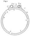
- the clamp 3 engages over the flanges 4 and 10 and pulls with conical side walls 11 and 12, which in the circumferential direction at equal angular intervals interruptions 13 (Fig. 4) to hold an outer strap 14 and thus the entire clamp flexible, the two flanges 4 and 10 when tightening together.
- the clamp 3 is tensioned by means of a screw 15.
- the screw 15 is passed through coaxial holes in a hinge sleeve 16 and screwed through coaxial threaded holes in a hinge sleeve 17.
- the hinge sleeves 16, 17 are surrounded by loops 18 which are formed by bent-back end portions of the tension band 14. The bent-back ends of the loops 18 are welded to the remaining part of the tension band 14.
- the clamping screw 15 is passed through slots in the loops.
- the second tube 2 has between the second flange 10 and its remaining tube portion 19 an elastically flexible cylindrical portion 20, whose inner diameter is greater than the outer diameter of the first tube 1 and the cylindrical extension 9.
- a transition section 21 (Fig. 1) between the cylindrical section 20 and the remaining pipe section 19 of the pipe 2 is conical and also elastically flexible.
- a sealing ring 22 made of resilient steel sheet in the tensioned state of the clamp 3 is clamped.
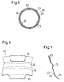
- FIGS. 2 and 5 to 7 show more clearly, eight edge sections 23 are bent back in the form of tabs onto part of the remaining sealing ring section 24.
- the remaining sealing ring portion 24 has a over the thickness of the bent edge portions 23 in the untensioned state of the clamp projecting bead 25 which extends over the entire circumference of the sealing ring 22.
- the radially inner edge of the sealing ring 22 is provided with three corresponding to the rounding 7 curved alignment tabs 26 at the same circumferential intervals.
- the flange 4 Due to the air trapped in the annulus between the first flange 4 and the tube 1, the flange 4 remains relatively cool when a hot fluid, such as hot exhaust gases, is passed through the tubes 1 and 2.
- the first flange 4 therefore expands less thermally in the radial direction than when it comes into direct contact with the hot fluid. But he can bend under the thermal, radial expansion pressure of the tube 1 with support on the clamp 3 radially inwardly, as its not welded to the tube 1 wall 6 slides along the free end of the tube 1, so that the radial expansion pressure of the tube. 1 is absorbed by the bending of the flange 4 for the most part without completely transferring to the clamp 3.
- the elastic cylindrical portion 20 has the advantage that it bends under the thermal expansion pressure in the second tube 2 and thus also receives a large part of the expansion pressure. At the same time allows the elasticity of the cylindrical portion 20, a bend or radial displacement of the two tubes 1, 2 relative to each other, if they are not exactly coaxial with each other due to a slight incorrect assembly.
- the cylindrical extension 9 of the rounding 7 of the second wall 6 of the flange 4 has the advantage that there is a gap or clearance between the cylindrical extension 9 of the wall 6 of the first flange 4 and the cylindrical portion 20, wherein the extension 9 at the same time a cylindrical Extension of the tube 1 forms and facilitates the mating of both tubes, since the Tube 2 is guided on the extension 9. At the same time both tubes 1, 2 can be largely centered, if they are not first brought together coaxially.
- the conicity and elasticity of the transition section 21 also facilitates a radial thermal expansion of the remaining portion 19 of the tube 2 relative to its cylindrical portion 20 and the second flange 12, so that the radial, thermal expansion pressure of the tube 2 on the clamp 3 in part by the transition section 21 is balanced.
- the existing steel sheet sealing ring 22 holds for a high temperatures stood, as they occur especially in exhaust pipes, but is still elastic in the region of its bead 25.
- This bead 25 receives not only the clamping pressure of the clamp 3, but partly also the axial thermal expansion of both tubes 1, 2 relative to each other, without completely deform back flat. This reversion is prevented by the fact that the bent-back edge portions 23 or tabs act as a stop for the second flange 10 of the tube 2.
- the elasticity of the bead 25 is thus largely retained.
- distributed edge portions 23 may also be provided over the entire circumference of the sealing ring 22 extending edge portion by flanging.
- individual edge sections 23 in the form of tabs can be bent over more easily than a marginal section of the sealing ring 22 that is continuously flanged over the circumference of the remaining sealing ring section 24.
- the bead 25 preferably extends over the entire circumference of the sealing ring 22. It can therefore be formed by a simple embossing tool. Alternatively, it would also be possible to divide the bead 25 into individual beads or provide radial, distributed over the circumference of the sealing ring 22 beads. However, these would have a higher rigidity than the over the entire circumference of the remaining sealing ring portion 24 extending bead 25th
Landscapes
- Engineering & Computer Science (AREA)
- General Engineering & Computer Science (AREA)
- Mechanical Engineering (AREA)
- Chemical & Material Sciences (AREA)
- Combustion & Propulsion (AREA)
- Flanged Joints, Insulating Joints, And Other Joints (AREA)
- Joints With Sleeves (AREA)
- Quick-Acting Or Multi-Walled Pipe Joints (AREA)
- Non-Disconnectible Joints And Screw-Threaded Joints (AREA)
- Earth Drilling (AREA)
- Joints Allowing Movement (AREA)
Priority Applications (1)
| Application Number | Priority Date | Filing Date | Title |
|---|---|---|---|
| EP10009860A EP2270381B1 (fr) | 2004-10-15 | 2005-09-30 | Raccordement de deux conduits et bague d'étanchéité pour le raccordement |
Applications Claiming Priority (1)
| Application Number | Priority Date | Filing Date | Title |
|---|---|---|---|
| DE102004050302A DE102004050302B4 (de) | 2004-10-15 | 2004-10-15 | Verbindung zweier Rohre und Dichtring für die Verbindung |
Related Child Applications (1)
| Application Number | Title | Priority Date | Filing Date |
|---|---|---|---|
| EP10009860.7 Division-Into | 2010-09-17 |
Publications (3)
| Publication Number | Publication Date |
|---|---|
| EP1647754A2 true EP1647754A2 (fr) | 2006-04-19 |
| EP1647754A3 EP1647754A3 (fr) | 2007-03-28 |
| EP1647754B1 EP1647754B1 (fr) | 2010-11-03 |
Family
ID=35615517
Family Applications (2)
| Application Number | Title | Priority Date | Filing Date |
|---|---|---|---|
| EP05021453A Expired - Lifetime EP1647754B1 (fr) | 2004-10-15 | 2005-09-30 | Raccordement de deux conduits |
| EP10009860A Expired - Lifetime EP2270381B1 (fr) | 2004-10-15 | 2005-09-30 | Raccordement de deux conduits et bague d'étanchéité pour le raccordement |
Family Applications After (1)
| Application Number | Title | Priority Date | Filing Date |
|---|---|---|---|
| EP10009860A Expired - Lifetime EP2270381B1 (fr) | 2004-10-15 | 2005-09-30 | Raccordement de deux conduits et bague d'étanchéité pour le raccordement |
Country Status (6)
| Country | Link |
|---|---|
| US (1) | US7393020B2 (fr) |
| EP (2) | EP1647754B1 (fr) |
| JP (1) | JP4134139B2 (fr) |
| AT (2) | ATE487081T1 (fr) |
| DE (2) | DE102004050302B4 (fr) |
| ES (2) | ES2374381T3 (fr) |
Cited By (8)
| Publication number | Priority date | Publication date | Assignee | Title |
|---|---|---|---|---|
| EP1873368A3 (fr) * | 2006-06-28 | 2008-02-06 | Witzenmann GmbH | Tuyau métallique flexible et anneau d'étanchéité |
| FR2935745A1 (fr) * | 2008-09-08 | 2010-03-12 | Faurecia Sys Echappement | Volume d'echappement pour vehicule automobile |
| EP2180163A3 (fr) * | 2008-10-21 | 2012-05-30 | Benteler Automobiltechnik GmbH | Boîtier de turbines et son procédé de fabrication |
| EP2385228A3 (fr) * | 2010-05-05 | 2014-06-25 | Metal Textiles Corporation | Raccord de tuyau et collier de serrage étanche |
| WO2017109458A1 (fr) * | 2015-12-22 | 2017-06-29 | Teconnex Ltd | Appareil de joint glissant amélioré et son procédé d'utilisation |
| FR3057947A1 (fr) * | 2016-10-26 | 2018-04-27 | Valeo Systemes Thermiques | Dispositif de raccord pour un echangeur thermique de vehicule automobile |
| EP3460307A1 (fr) * | 2017-09-22 | 2019-03-27 | NORMA Germany GmbH | Collier profilé à élément d'étanchéité |
| CN112814773A (zh) * | 2019-11-15 | 2021-05-18 | 马自达汽车株式会社 | 内燃机搭载车辆的排气管结构及内燃机搭载车辆制造方法 |
Families Citing this family (19)
| Publication number | Priority date | Publication date | Assignee | Title |
|---|---|---|---|---|
| FR2833065B1 (fr) * | 2001-12-05 | 2004-09-03 | Caillau Ets | Systeme de serrage pour le raccordement etanche de deux tubes ayant des surfaces d'appui |
| JP4917069B2 (ja) * | 2008-04-28 | 2012-04-18 | 株式会社流機エンジニアリング | 送風ダクト |
| US9285066B2 (en) * | 2009-01-15 | 2016-03-15 | Cheminee Securite International Ltee | Positive pressure pipe coupling |
| DE102009039862B4 (de) * | 2009-09-03 | 2013-04-18 | Norma Germany Gmbh | Profilschelle |
| CN104964111B (zh) * | 2009-09-29 | 2017-12-12 | 卡明斯Ip公司 | 球形法兰接头 |
| US20110181037A1 (en) * | 2010-01-22 | 2011-07-28 | International Engine Intellectual Property Company Llc | Alignment clamp |
| DE102010025031A1 (de) * | 2010-06-24 | 2011-12-29 | Benteler Automobiltechnik Gmbh | Wärmetauscher |
| FR2963404B1 (fr) * | 2010-07-27 | 2014-02-07 | Caillau Ets | Systeme de serrage pour le raccordement et le pre-montage d'un premier et d'un deuxieme tube |
| DE102012006756B3 (de) * | 2012-04-03 | 2013-09-12 | Norma Germany Gmbh | Verbindungsanordnung für eine Kegelflanschverbindung und Kegelflanschverbindung |
| GB201209696D0 (en) * | 2012-05-31 | 2012-07-18 | Teconnex Ltd | Clamping means and method of use thereof |
| DE102013219349A1 (de) * | 2012-09-27 | 2014-05-28 | Ifm Electronic Gmbh | Temperatursensor für Hygieneanwendungen mit klemmbaren Prozessanschluss |
| DE102013212545B4 (de) * | 2013-06-28 | 2015-04-02 | Saf-Holland Gmbh | Schale |
| FR3008160B1 (fr) * | 2013-07-03 | 2015-10-09 | Caillau Ets | Dispositif de serrage comprenant un collier et un manchon |
| US20150226368A1 (en) * | 2014-02-12 | 2015-08-13 | Nelson Global Products | Insulated Tube Joint Connection |
| US9926956B2 (en) | 2016-02-19 | 2018-03-27 | Cummins Emission Solutions Inc. | Dual purpose clamp for securing aftertreatment housing joints |
| FR3087868B1 (fr) * | 2018-10-25 | 2021-05-07 | Airbus Operations Sas | Dispositif de raccordement de deux conduits d’une canalisation comportant un jeu de collerettes tronconiques et canalisation comprenant ledit dispositif de raccordement |
| DE102019126484A1 (de) * | 2019-10-01 | 2021-04-01 | Norma Germany Gmbh | Profilschelle mit Verrastlasche |
| DE102020100285A1 (de) * | 2020-01-09 | 2021-07-15 | Eberspächer Exhaust Technology GmbH | Abgasanlage |
| US12435659B2 (en) | 2023-02-01 | 2025-10-07 | Cummins Emission Solutions Inc. | Aftertreatment component cartridge for an aftertreatment system |
Family Cites Families (22)
| Publication number | Priority date | Publication date | Assignee | Title |
|---|---|---|---|---|
| US805645A (en) * | 1904-03-19 | 1905-11-28 | James W Guillott | Gasket. |
| FR8073E (fr) | 1906-10-26 | 1908-01-08 | Julien Marie Adrien Rivals | Servo-moteur électrique de relais |
| DE890588C (de) * | 1950-08-22 | 1953-09-21 | Max Dr-Ing Natter | Luttenverbindung |
| US2761707A (en) * | 1954-12-16 | 1956-09-04 | Aeroquip Corp | Tube coupling with impressionable metallic seal |
| US3180662A (en) * | 1958-07-10 | 1965-04-27 | Flexonics Corp | Tube coupling having a springy metallic gasket |
| US3455582A (en) * | 1967-10-11 | 1969-07-15 | Hanlon & Wilson Co | Multiple segment v-type flange slip joint coupling |
| US3633928A (en) | 1970-03-05 | 1972-01-11 | Douglas Smith | Pipe joint coupling with gasket seal |
| US3674291A (en) * | 1970-11-30 | 1972-07-04 | Lockheed Aircraft Corp | Flange for conduit coupling |
| CH555022A (de) * | 1972-08-10 | 1974-10-15 | Oetiker Hans | Rohrverbindung. |
| US3820831A (en) * | 1973-02-20 | 1974-06-28 | J Swedelius | Coupling for connecting aligned tubes |
| US3964773A (en) * | 1974-09-13 | 1976-06-22 | Mercury Metal Products, Inc. | Anti-emission exhaust pipe joint and clamp therefor |
| US4175754A (en) * | 1978-05-08 | 1979-11-27 | Lockheed Corporation | Seal for fluid ducts |
| US4579374A (en) * | 1982-04-01 | 1986-04-01 | Hymatic Clamps International Limited | Joint structure for connecting hollow members |
| US4597596A (en) * | 1984-11-07 | 1986-07-01 | Heat Transfer Technology Limited | Cylinder end seal |
| US5213345A (en) * | 1986-11-10 | 1993-05-25 | Ishikawa Gasket Co., Ltd. | Steel laminate gasket with wide sealing area |
| JP2841250B2 (ja) * | 1991-09-05 | 1998-12-24 | 日本ガスケット株式会社 | 金属製ガスケット及びその製造方法 |
| DE4219241A1 (de) * | 1992-06-12 | 1992-10-22 | Witzenmann Metallschlauchfab | Gelenkige verbindung von rohrteilen, insbesondere bei abgasleitungen von kraftfahrzeugen |
| US5582415A (en) * | 1993-08-31 | 1996-12-10 | Kokusan Parts Industry Co., Ltd. | Metal gasket |
| US5505498A (en) * | 1994-05-16 | 1996-04-09 | Eg&G Pressure Science, Inc. | Flexible pressure-energized joint |
| US6209883B1 (en) * | 1998-03-04 | 2001-04-03 | Dana Corporation | Single layer head gasket with integral stopper and method of making the same |
| FR2810716B1 (fr) * | 2000-06-23 | 2002-10-04 | Peugeot Citroen Automobiles Sa | Dispositif d'accouplement de deux elements tubulaires formant notamment des elements d'une ligne d'echappement de vehicule automobile |
| FR2867511B1 (fr) * | 2004-03-09 | 2009-04-24 | Faurecia Sys Echappement | Dispositif d'assemblage reversible d'un premier et d'un second troncon tubulaire d'une ligne d'echappement et joint d'etancheite pour un tel dispositif d'assemblage |
-
2004
- 2004-10-15 DE DE102004050302A patent/DE102004050302B4/de not_active Expired - Fee Related
-
2005
- 2005-09-30 AT AT05021453T patent/ATE487081T1/de active
- 2005-09-30 DE DE502005010471T patent/DE502005010471D1/de not_active Expired - Lifetime
- 2005-09-30 ES ES10009860T patent/ES2374381T3/es not_active Expired - Lifetime
- 2005-09-30 AT AT10009860T patent/ATE531989T1/de active
- 2005-09-30 EP EP05021453A patent/EP1647754B1/fr not_active Expired - Lifetime
- 2005-09-30 EP EP10009860A patent/EP2270381B1/fr not_active Expired - Lifetime
- 2005-09-30 ES ES05021453T patent/ES2351979T3/es not_active Expired - Lifetime
- 2005-10-14 US US11/251,052 patent/US7393020B2/en not_active Expired - Fee Related
- 2005-10-14 JP JP2005300232A patent/JP4134139B2/ja not_active Expired - Fee Related
Non-Patent Citations (1)
| Title |
|---|
| "NORMA® PROFILSCHELLEN KEGELFLANSCHVERBIN- DUNGEN", September 1987, pages: 6 |
Cited By (12)
| Publication number | Priority date | Publication date | Assignee | Title |
|---|---|---|---|---|
| EP1873368A3 (fr) * | 2006-06-28 | 2008-02-06 | Witzenmann GmbH | Tuyau métallique flexible et anneau d'étanchéité |
| FR2935745A1 (fr) * | 2008-09-08 | 2010-03-12 | Faurecia Sys Echappement | Volume d'echappement pour vehicule automobile |
| EP2180163A3 (fr) * | 2008-10-21 | 2012-05-30 | Benteler Automobiltechnik GmbH | Boîtier de turbines et son procédé de fabrication |
| EP2385228A3 (fr) * | 2010-05-05 | 2014-06-25 | Metal Textiles Corporation | Raccord de tuyau et collier de serrage étanche |
| WO2017109458A1 (fr) * | 2015-12-22 | 2017-06-29 | Teconnex Ltd | Appareil de joint glissant amélioré et son procédé d'utilisation |
| FR3057947A1 (fr) * | 2016-10-26 | 2018-04-27 | Valeo Systemes Thermiques | Dispositif de raccord pour un echangeur thermique de vehicule automobile |
| WO2018078238A1 (fr) * | 2016-10-26 | 2018-05-03 | Valeo Systemes Thermiques | Dispositif de raccord pour un echangeur thermique de vehicule automobile |
| EP3460307A1 (fr) * | 2017-09-22 | 2019-03-27 | NORMA Germany GmbH | Collier profilé à élément d'étanchéité |
| CN109538853A (zh) * | 2017-09-22 | 2019-03-29 | 德国诺玛公司 | 具有密封组件的型材夹具 |
| US10794518B2 (en) | 2017-09-22 | 2020-10-06 | Norma Germany Gmbh | Profile clamp having sealing element |
| CN112814773A (zh) * | 2019-11-15 | 2021-05-18 | 马自达汽车株式会社 | 内燃机搭载车辆的排气管结构及内燃机搭载车辆制造方法 |
| EP3822466A1 (fr) * | 2019-11-15 | 2021-05-19 | Mazda Motor Corporation | Structure de tuyau d'échappement de véhicule, véhicule et procédé de fabrication du véhicule |
Also Published As
| Publication number | Publication date |
|---|---|
| DE102004050302B4 (de) | 2010-09-30 |
| ES2351979T3 (es) | 2011-02-14 |
| DE502005010471D1 (de) | 2010-12-16 |
| ES2374381T3 (es) | 2012-02-16 |
| DE102004050302A1 (de) | 2006-05-04 |
| EP1647754B1 (fr) | 2010-11-03 |
| US7393020B2 (en) | 2008-07-01 |
| EP1647754A3 (fr) | 2007-03-28 |
| EP2270381B1 (fr) | 2011-11-02 |
| EP2270381A1 (fr) | 2011-01-05 |
| ATE487081T1 (de) | 2010-11-15 |
| ATE531989T1 (de) | 2011-11-15 |
| JP4134139B2 (ja) | 2008-08-13 |
| US20060082154A1 (en) | 2006-04-20 |
| JP2006112631A (ja) | 2006-04-27 |
Similar Documents
| Publication | Publication Date | Title |
|---|---|---|
| EP1647754B1 (fr) | Raccordement de deux conduits | |
| DE69825637T2 (de) | Dichtring für röhrenförmiges Element | |
| DE69411935T2 (de) | Schlauchschelle | |
| DE3605020C2 (fr) | ||
| DE102004050300A1 (de) | Profilschelle | |
| DE19514940C1 (de) | Rohrkupplung | |
| EP3460307A1 (fr) | Collier profilé à élément d'étanchéité | |
| EP0214395A1 (fr) | Raccord élastique de tuyaux et spécialement raccord flexible | |
| EP2193303B1 (fr) | Raccord à presser pour un tube, notamment pour un tube plastique ou tuyau composite constitué de plastique et de métal | |
| DE69703856T2 (de) | Kupplung für zwei Metallrohre | |
| DE102007008759B3 (de) | Pressfitting für ein Rohr | |
| DE102012005943A1 (de) | Vorrichtung zum Verbinden von zwei Rundkörpern mit unterschiedlichen Außendurchmessern | |
| EP0498322B1 (fr) | Dispositif d'étanchéité pour l'assemblage de deux extrémités à tuyaux cylindriques et lisses | |
| DE102006029242B4 (de) | Flanschverbindung | |
| DE102010009618A1 (de) | Anschlussvorrichtung für ein modulares Installationssystem | |
| WO2000060265A1 (fr) | Dispositif de raccordement de tuyaux | |
| DE19539824C1 (de) | Rohrschelle | |
| DE3445662A1 (de) | Anschlusshuelse an metallringwellschlauch | |
| DE102004056792B4 (de) | Rohrverbindung | |
| DE3047382A1 (de) | "rohrverbindung" | |
| DE29822752U1 (de) | Nichtlösbare Rohrverbindung | |
| DE202006019578U1 (de) | Presshülse für eine Pressverbindung von Rohren | |
| EP1298374B2 (fr) | Système de tuyaux et collier de serrage pour système de tuyaux | |
| DE202019100995U1 (de) | Halteelement und Rohrverbindungsanordnung | |
| DE102008058461A1 (de) | Kugelzonenverbindungsvorrichtung |
Legal Events
| Date | Code | Title | Description |
|---|---|---|---|
| PUAI | Public reference made under article 153(3) epc to a published international application that has entered the european phase |
Free format text: ORIGINAL CODE: 0009012 |
|
| 17P | Request for examination filed |
Effective date: 20060222 |
|
| AK | Designated contracting states |
Kind code of ref document: A2 Designated state(s): AT BE BG CH CY CZ DE DK EE ES FI FR GB GR HU IE IS IT LI LT LU LV MC NL PL PT RO SE SI SK TR |
|
| AX | Request for extension of the european patent |
Extension state: AL BA HR MK YU |
|
| PUAL | Search report despatched |
Free format text: ORIGINAL CODE: 0009013 |
|
| AK | Designated contracting states |
Kind code of ref document: A3 Designated state(s): AT BE BG CH CY CZ DE DK EE ES FI FR GB GR HU IE IS IT LI LT LU LV MC NL PL PT RO SE SI SK TR |
|
| AX | Request for extension of the european patent |
Extension state: AL BA HR MK YU |
|
| RAP1 | Party data changed (applicant data changed or rights of an application transferred) |
Owner name: NORMA GERMANY GMBH |
|
| AKX | Designation fees paid |
Designated state(s): AT BE BG CH CY CZ DE DK EE ES FI FR GB GR HU IE IS IT LI LT LU LV MC NL PL PT RO SE SI SK TR |
|
| GRAP | Despatch of communication of intention to grant a patent |
Free format text: ORIGINAL CODE: EPIDOSNIGR1 |
|
| RTI1 | Title (correction) |
Free format text: CONNECTION OF TWO PIPES |
|
| GRAS | Grant fee paid |
Free format text: ORIGINAL CODE: EPIDOSNIGR3 |
|
| RAP1 | Party data changed (applicant data changed or rights of an application transferred) |
Owner name: NORMA GERMANY GMBH |
|
| GRAA | (expected) grant |
Free format text: ORIGINAL CODE: 0009210 |
|
| AK | Designated contracting states |
Kind code of ref document: B1 Designated state(s): AT BE BG CH CY CZ DE DK EE ES FI FR GB GR HU IE IS IT LI LT LU LV MC NL PL PT RO SE SI SK TR |
|
| REG | Reference to a national code |
Ref country code: GB Ref legal event code: FG4D Free format text: NOT ENGLISH |
|
| REG | Reference to a national code |
Ref country code: CH Ref legal event code: EP |
|
| REG | Reference to a national code |
Ref country code: IE Ref legal event code: FG4D Free format text: LANGUAGE OF EP DOCUMENT: GERMAN |
|
| REF | Corresponds to: |
Ref document number: 502005010471 Country of ref document: DE Date of ref document: 20101216 Kind code of ref document: P |
|
| REG | Reference to a national code |
Ref country code: SE Ref legal event code: TRGR |
|
| REG | Reference to a national code |
Ref country code: ES Ref legal event code: FG2A Effective date: 20110202 |
|
| REG | Reference to a national code |
Ref country code: NL Ref legal event code: VDEP Effective date: 20101103 |
|
| LTIE | Lt: invalidation of european patent or patent extension |
Effective date: 20101103 |
|
| PG25 | Lapsed in a contracting state [announced via postgrant information from national office to epo] |
Ref country code: LT Free format text: LAPSE BECAUSE OF FAILURE TO SUBMIT A TRANSLATION OF THE DESCRIPTION OR TO PAY THE FEE WITHIN THE PRESCRIBED TIME-LIMIT Effective date: 20101103 |
|
| REG | Reference to a national code |
Ref country code: IE Ref legal event code: FD4D |
|
| PG25 | Lapsed in a contracting state [announced via postgrant information from national office to epo] |
Ref country code: PT Free format text: LAPSE BECAUSE OF FAILURE TO SUBMIT A TRANSLATION OF THE DESCRIPTION OR TO PAY THE FEE WITHIN THE PRESCRIBED TIME-LIMIT Effective date: 20110303 Ref country code: LV Free format text: LAPSE BECAUSE OF FAILURE TO SUBMIT A TRANSLATION OF THE DESCRIPTION OR TO PAY THE FEE WITHIN THE PRESCRIBED TIME-LIMIT Effective date: 20101103 Ref country code: IS Free format text: LAPSE BECAUSE OF FAILURE TO SUBMIT A TRANSLATION OF THE DESCRIPTION OR TO PAY THE FEE WITHIN THE PRESCRIBED TIME-LIMIT Effective date: 20110303 Ref country code: FI Free format text: LAPSE BECAUSE OF FAILURE TO SUBMIT A TRANSLATION OF THE DESCRIPTION OR TO PAY THE FEE WITHIN THE PRESCRIBED TIME-LIMIT Effective date: 20101103 Ref country code: NL Free format text: LAPSE BECAUSE OF FAILURE TO SUBMIT A TRANSLATION OF THE DESCRIPTION OR TO PAY THE FEE WITHIN THE PRESCRIBED TIME-LIMIT Effective date: 20101103 Ref country code: BG Free format text: LAPSE BECAUSE OF FAILURE TO SUBMIT A TRANSLATION OF THE DESCRIPTION OR TO PAY THE FEE WITHIN THE PRESCRIBED TIME-LIMIT Effective date: 20110203 Ref country code: SI Free format text: LAPSE BECAUSE OF FAILURE TO SUBMIT A TRANSLATION OF THE DESCRIPTION OR TO PAY THE FEE WITHIN THE PRESCRIBED TIME-LIMIT Effective date: 20101103 |
|
| PG25 | Lapsed in a contracting state [announced via postgrant information from national office to epo] |
Ref country code: GR Free format text: LAPSE BECAUSE OF FAILURE TO SUBMIT A TRANSLATION OF THE DESCRIPTION OR TO PAY THE FEE WITHIN THE PRESCRIBED TIME-LIMIT Effective date: 20110204 |
|
| PG25 | Lapsed in a contracting state [announced via postgrant information from national office to epo] |
Ref country code: EE Free format text: LAPSE BECAUSE OF FAILURE TO SUBMIT A TRANSLATION OF THE DESCRIPTION OR TO PAY THE FEE WITHIN THE PRESCRIBED TIME-LIMIT Effective date: 20101103 Ref country code: IE Free format text: LAPSE BECAUSE OF FAILURE TO SUBMIT A TRANSLATION OF THE DESCRIPTION OR TO PAY THE FEE WITHIN THE PRESCRIBED TIME-LIMIT Effective date: 20101103 Ref country code: CZ Free format text: LAPSE BECAUSE OF FAILURE TO SUBMIT A TRANSLATION OF THE DESCRIPTION OR TO PAY THE FEE WITHIN THE PRESCRIBED TIME-LIMIT Effective date: 20101103 |
|
| PG25 | Lapsed in a contracting state [announced via postgrant information from national office to epo] |
Ref country code: DK Free format text: LAPSE BECAUSE OF FAILURE TO SUBMIT A TRANSLATION OF THE DESCRIPTION OR TO PAY THE FEE WITHIN THE PRESCRIBED TIME-LIMIT Effective date: 20101103 Ref country code: SK Free format text: LAPSE BECAUSE OF FAILURE TO SUBMIT A TRANSLATION OF THE DESCRIPTION OR TO PAY THE FEE WITHIN THE PRESCRIBED TIME-LIMIT Effective date: 20101103 Ref country code: RO Free format text: LAPSE BECAUSE OF FAILURE TO SUBMIT A TRANSLATION OF THE DESCRIPTION OR TO PAY THE FEE WITHIN THE PRESCRIBED TIME-LIMIT Effective date: 20101103 Ref country code: PL Free format text: LAPSE BECAUSE OF FAILURE TO SUBMIT A TRANSLATION OF THE DESCRIPTION OR TO PAY THE FEE WITHIN THE PRESCRIBED TIME-LIMIT Effective date: 20101103 |
|
| PLBE | No opposition filed within time limit |
Free format text: ORIGINAL CODE: 0009261 |
|
| STAA | Information on the status of an ep patent application or granted ep patent |
Free format text: STATUS: NO OPPOSITION FILED WITHIN TIME LIMIT |
|
| 26N | No opposition filed |
Effective date: 20110804 |
|
| PGFP | Annual fee paid to national office [announced via postgrant information from national office to epo] |
Ref country code: GB Payment date: 20110923 Year of fee payment: 7 Ref country code: SE Payment date: 20110923 Year of fee payment: 7 Ref country code: FR Payment date: 20111005 Year of fee payment: 7 Ref country code: ES Payment date: 20110923 Year of fee payment: 7 Ref country code: DE Payment date: 20110916 Year of fee payment: 7 |
|
| REG | Reference to a national code |
Ref country code: DE Ref legal event code: R097 Ref document number: 502005010471 Country of ref document: DE Effective date: 20110804 |
|
| BERE | Be: lapsed |
Owner name: NORMA GERMANY G.M.B.H. Effective date: 20110930 |
|
| PG25 | Lapsed in a contracting state [announced via postgrant information from national office to epo] |
Ref country code: MC Free format text: LAPSE BECAUSE OF NON-PAYMENT OF DUE FEES Effective date: 20110930 |
|
| REG | Reference to a national code |
Ref country code: CH Ref legal event code: PL |
|
| PG25 | Lapsed in a contracting state [announced via postgrant information from national office to epo] |
Ref country code: BE Free format text: LAPSE BECAUSE OF NON-PAYMENT OF DUE FEES Effective date: 20110930 |
|
| PG25 | Lapsed in a contracting state [announced via postgrant information from national office to epo] |
Ref country code: CH Free format text: LAPSE BECAUSE OF NON-PAYMENT OF DUE FEES Effective date: 20110930 Ref country code: LI Free format text: LAPSE BECAUSE OF NON-PAYMENT OF DUE FEES Effective date: 20110930 |
|
| REG | Reference to a national code |
Ref country code: AT Ref legal event code: MM01 Ref document number: 487081 Country of ref document: AT Kind code of ref document: T Effective date: 20110930 |
|
| PG25 | Lapsed in a contracting state [announced via postgrant information from national office to epo] |
Ref country code: AT Free format text: LAPSE BECAUSE OF NON-PAYMENT OF DUE FEES Effective date: 20110930 |
|
| GBPC | Gb: european patent ceased through non-payment of renewal fee |
Effective date: 20120930 |
|
| PG25 | Lapsed in a contracting state [announced via postgrant information from national office to epo] |
Ref country code: CY Free format text: LAPSE BECAUSE OF EXPIRATION OF PROTECTION Effective date: 20101103 Ref country code: LU Free format text: LAPSE BECAUSE OF NON-PAYMENT OF DUE FEES Effective date: 20110930 |
|
| REG | Reference to a national code |
Ref country code: FR Ref legal event code: ST Effective date: 20130531 |
|
| PG25 | Lapsed in a contracting state [announced via postgrant information from national office to epo] |
Ref country code: SE Free format text: LAPSE BECAUSE OF NON-PAYMENT OF DUE FEES Effective date: 20121001 Ref country code: GB Free format text: LAPSE BECAUSE OF NON-PAYMENT OF DUE FEES Effective date: 20120930 Ref country code: DE Free format text: LAPSE BECAUSE OF NON-PAYMENT OF DUE FEES Effective date: 20130403 |
|
| PG25 | Lapsed in a contracting state [announced via postgrant information from national office to epo] |
Ref country code: FR Free format text: LAPSE BECAUSE OF NON-PAYMENT OF DUE FEES Effective date: 20121001 Ref country code: IT Free format text: LAPSE BECAUSE OF NON-PAYMENT OF DUE FEES Effective date: 20120930 |
|
| REG | Reference to a national code |
Ref country code: DE Ref legal event code: R119 Ref document number: 502005010471 Country of ref document: DE Effective date: 20130403 |
|
| PG25 | Lapsed in a contracting state [announced via postgrant information from national office to epo] |
Ref country code: TR Free format text: LAPSE BECAUSE OF FAILURE TO SUBMIT A TRANSLATION OF THE DESCRIPTION OR TO PAY THE FEE WITHIN THE PRESCRIBED TIME-LIMIT Effective date: 20101103 |
|
| REG | Reference to a national code |
Ref country code: ES Ref legal event code: FD2A Effective date: 20131023 |
|
| PG25 | Lapsed in a contracting state [announced via postgrant information from national office to epo] |
Ref country code: HU Free format text: LAPSE BECAUSE OF FAILURE TO SUBMIT A TRANSLATION OF THE DESCRIPTION OR TO PAY THE FEE WITHIN THE PRESCRIBED TIME-LIMIT Effective date: 20101103 |
|
| PG25 | Lapsed in a contracting state [announced via postgrant information from national office to epo] |
Ref country code: ES Free format text: LAPSE BECAUSE OF NON-PAYMENT OF DUE FEES Effective date: 20121001 |