EP1647820A2 - Procédé et dispositif de détection de gaz par spectroscopie d'absorption - Google Patents
Procédé et dispositif de détection de gaz par spectroscopie d'absorption Download PDFInfo
- Publication number
- EP1647820A2 EP1647820A2 EP06000797A EP06000797A EP1647820A2 EP 1647820 A2 EP1647820 A2 EP 1647820A2 EP 06000797 A EP06000797 A EP 06000797A EP 06000797 A EP06000797 A EP 06000797A EP 1647820 A2 EP1647820 A2 EP 1647820A2
- Authority
- EP
- European Patent Office
- Prior art keywords
- gas
- cell
- concentration
- measuring
- mirror
- Prior art date
- Legal status (The legal status is an assumption and is not a legal conclusion. Google has not performed a legal analysis and makes no representation as to the accuracy of the status listed.)
- Granted
Links
Images


Classifications
-
- G—PHYSICS
- G01—MEASURING; TESTING
- G01N—INVESTIGATING OR ANALYSING MATERIALS BY DETERMINING THEIR CHEMICAL OR PHYSICAL PROPERTIES
- G01N21/00—Investigating or analysing materials by the use of optical means, i.e. using sub-millimetre waves, infrared, visible or ultraviolet light
- G01N21/17—Systems in which incident light is modified in accordance with the properties of the material investigated
- G01N21/25—Colour; Spectral properties, i.e. comparison of effect of material on the light at two or more different wavelengths or wavelength bands
- G01N21/31—Investigating relative effect of material at wavelengths characteristic of specific elements or molecules, e.g. atomic absorption spectrometry
- G01N21/35—Investigating relative effect of material at wavelengths characteristic of specific elements or molecules, e.g. atomic absorption spectrometry using infrared light
- G01N21/3504—Investigating relative effect of material at wavelengths characteristic of specific elements or molecules, e.g. atomic absorption spectrometry using infrared light for analysing gases, e.g. multi-gas analysis
-
- G—PHYSICS
- G01—MEASURING; TESTING
- G01J—MEASUREMENT OF INTENSITY, VELOCITY, SPECTRAL CONTENT, POLARISATION, PHASE OR PULSE CHARACTERISTICS OF INFRARED, VISIBLE OR ULTRAVIOLET LIGHT; COLORIMETRY; RADIATION PYROMETRY
- G01J3/00—Spectrometry; Spectrophotometry; Monochromators; Measuring colours
- G01J3/28—Investigating the spectrum
- G01J3/42—Absorption spectrometry; Double beam spectrometry; Flicker spectrometry; Reflection spectrometry
-
- G—PHYSICS
- G01—MEASURING; TESTING
- G01N—INVESTIGATING OR ANALYSING MATERIALS BY DETERMINING THEIR CHEMICAL OR PHYSICAL PROPERTIES
- G01N21/00—Investigating or analysing materials by the use of optical means, i.e. using sub-millimetre waves, infrared, visible or ultraviolet light
- G01N21/01—Arrangements or apparatus for facilitating the optical investigation
- G01N21/03—Cuvette constructions
- G01N21/031—Multipass arrangements
-
- G—PHYSICS
- G01—MEASURING; TESTING
- G01N—INVESTIGATING OR ANALYSING MATERIALS BY DETERMINING THEIR CHEMICAL OR PHYSICAL PROPERTIES
- G01N21/00—Investigating or analysing materials by the use of optical means, i.e. using sub-millimetre waves, infrared, visible or ultraviolet light
- G01N21/17—Systems in which incident light is modified in accordance with the properties of the material investigated
- G01N21/25—Colour; Spectral properties, i.e. comparison of effect of material on the light at two or more different wavelengths or wavelength bands
- G01N21/31—Investigating relative effect of material at wavelengths characteristic of specific elements or molecules, e.g. atomic absorption spectrometry
- G01N21/39—Investigating relative effect of material at wavelengths characteristic of specific elements or molecules, e.g. atomic absorption spectrometry using tunable lasers
-
- G—PHYSICS
- G01—MEASURING; TESTING
- G01J—MEASUREMENT OF INTENSITY, VELOCITY, SPECTRAL CONTENT, POLARISATION, PHASE OR PULSE CHARACTERISTICS OF INFRARED, VISIBLE OR ULTRAVIOLET LIGHT; COLORIMETRY; RADIATION PYROMETRY
- G01J3/00—Spectrometry; Spectrophotometry; Monochromators; Measuring colours
- G01J3/28—Investigating the spectrum
- G01J3/42—Absorption spectrometry; Double beam spectrometry; Flicker spectrometry; Reflection spectrometry
- G01J2003/423—Spectral arrangements using lasers, e.g. tunable
-
- G—PHYSICS
- G01—MEASURING; TESTING
- G01N—INVESTIGATING OR ANALYSING MATERIALS BY DETERMINING THEIR CHEMICAL OR PHYSICAL PROPERTIES
- G01N21/00—Investigating or analysing materials by the use of optical means, i.e. using sub-millimetre waves, infrared, visible or ultraviolet light
- G01N21/01—Arrangements or apparatus for facilitating the optical investigation
- G01N21/03—Cuvette constructions
- G01N21/0303—Optical path conditioning in cuvettes, e.g. windows; adapted optical elements or systems; path modifying or adjustment
- G01N2021/0307—Insert part in cell
-
- G—PHYSICS
- G01—MEASURING; TESTING
- G01N—INVESTIGATING OR ANALYSING MATERIALS BY DETERMINING THEIR CHEMICAL OR PHYSICAL PROPERTIES
- G01N21/00—Investigating or analysing materials by the use of optical means, i.e. using sub-millimetre waves, infrared, visible or ultraviolet light
- G01N21/01—Arrangements or apparatus for facilitating the optical investigation
- G01N21/03—Cuvette constructions
- G01N21/05—Flow-through cuvettes
- G01N2021/052—Tubular type; cavity type; multireflective
-
- G—PHYSICS
- G01—MEASURING; TESTING
- G01N—INVESTIGATING OR ANALYSING MATERIALS BY DETERMINING THEIR CHEMICAL OR PHYSICAL PROPERTIES
- G01N21/00—Investigating or analysing materials by the use of optical means, i.e. using sub-millimetre waves, infrared, visible or ultraviolet light
- G01N21/17—Systems in which incident light is modified in accordance with the properties of the material investigated
- G01N21/25—Colour; Spectral properties, i.e. comparison of effect of material on the light at two or more different wavelengths or wavelength bands
- G01N21/31—Investigating relative effect of material at wavelengths characteristic of specific elements or molecules, e.g. atomic absorption spectrometry
- G01N21/39—Investigating relative effect of material at wavelengths characteristic of specific elements or molecules, e.g. atomic absorption spectrometry using tunable lasers
- G01N2021/396—Type of laser source
- G01N2021/399—Diode laser
-
- G—PHYSICS
- G01—MEASURING; TESTING
- G01N—INVESTIGATING OR ANALYSING MATERIALS BY DETERMINING THEIR CHEMICAL OR PHYSICAL PROPERTIES
- G01N2201/00—Features of devices classified in G01N21/00
- G01N2201/06—Illumination; Optics
- G01N2201/061—Sources
- G01N2201/06113—Coherent sources; lasers
- G01N2201/0612—Laser diodes
-
- G—PHYSICS
- G01—MEASURING; TESTING
- G01N—INVESTIGATING OR ANALYSING MATERIALS BY DETERMINING THEIR CHEMICAL OR PHYSICAL PROPERTIES
- G01N2201/00—Features of devices classified in G01N21/00
- G01N2201/06—Illumination; Optics
- G01N2201/062—LED's
Definitions
- a common means of distributing energy around the world is by the transmission of gas, usually natural gas, but in some areas of the world manufactured gasses are also transmitted for use in homes and factories.
- Gas is typically transmitted through underground pipelines having branches that extend into homes and other buildings for use in providing energy for space and water heating.
- Many thousands of miles of gas pipeline exists in virtually every major city of the world. Since gas is useable only because it is highly combustible, gas leakage is a serious concern. For this reason much effort has been made to provide instrumentation for detecting small amounts of gas so that leaks can be located to permit repairs.
- a known and successful system for detecting small quantities of gas in the environment is by the use of absorption spectroscopy.
- a light beam of a selected frequency that is highly absorbed by the particular gas for which the instrument is designed is passed through a sample of the gas.
- the rate of absorption of the light beam is used as an indicator of the level of concentration of the gas in the sample.
- a basic element of natural gas, and most manufactured gasses used for room and water heating around the world, is methane.
- a typical absorption cell is an elongated cylinder in which mirrors are disposed at opposite ends and light is introduced into the cells through a hole in one of the mirrors.
- Herriott cells Because of the early work by Herriott in the development of light absorption spectroscopy using a cell having opposed mirrors in which a light beam is repeatedly reflected, such instruments are frequently referred to as "Herriott cells.”
- the invention herein relates to improvements and innovations in the construction, operation and use of Herriott type cells for detecting a selected gas, such as methane.
- the invention herein provides methods and systems for detecting and measuring the level of concentration of a preselected gas using an instrument that is more portable, rugged and sensitive than other instruments and systems currently available.
- a method of detecting a preselected gas includes the steps of continuously moving a stream of sample gas through a confined testing area within a detecting instrument.
- a light source such as a laser emitting diode or a light emitting diode is energized within the test instrument to emit a beam of frequency that is highly absorbed by the preselected gas.
- the beam is passed through the stream of gas within the confined testing area by bouncing the beam repeatedly between spaced apart mirrors in a Herriott type cell so that the length of travel of the beam within the test gas is greatly extended. Absorption of the beam is measured to provide an indication of the presence of the preselected gas.
- the frequency of light emitted by a typical light source is affected by the temperature of the light source and therefore the temperature must be regulated.
- the heat control assembly includes a heat sink having cooling fins that are exposed to the stream of sample gas, the light source being mounted in contact with a peltier element that in turn is in heat conductive relationship with the heat sink.
- a thermistor senses the temperature of the heat sink and sends a control signal to a microprocessor that in turn sends temperature adjustment instructions to a power supply which then provides adjusted current to the peltier that adjusts the temperature of the light source.
- the Herriott type cell as used in the gas detection instrument of this invention is significantly improved by the incorporation of a central axle member that provides a confined annular shaped test area for the sample gas through which the light beam moves.
- a system employing three photo detectors -- that is: (a) a reference photo detector; (b) a multi-path photo detector; and (c) a single or direct path photo detector.
- the Herriott type absorption spectroscopy cell as used herein is improved in important ways including the provision wherein a light beam enters through an aperture in a first mirror and exists, after multiple passes, through an aperture in a second mirror to encounter a multi-pass photo detector. Simultaneously provision is made for measuring absorption after a single pass of the light beam. Activation of the reference photo detector is achieved by a beam splitter window.
- the invention herein provides a highly portable yet rugged system that it easily adaptable to mounting in a vehicle so that test samples can be continuously picked up from the environment and cycled through the test system while the vehicle is moving to enable an operator to expeditiously survey a relatively large geographical area.
- This highly portable system used in a vehicle provides readouts coordinated with a global positioning monitor so that gas level intensities of a geographical area can be quickly and accurately mapped.
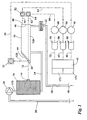
- FIG. 1 a block diagram of the major components of a system that can be used in practicing the methods of this invention are illustrated.
- the heart of the system is a cell 10 that will be described in detail subsequently, and that provides an environment in which a light beam 12 passes through a gas sample and in which absorption of the light beam is measured.
- a light beam is provided by a laser diode, in which case light beam 12 is a laser light beam.
- a light source that provides a non-coherent light beam.
- An example of a non-coherent light source is a light emitting diode (LED).
- a laser diode provides a coherent light beam that is a beam of substantially uniform frequency light having the characteristic that the laser light beam does not disperse to the same extent as a non-coherent light beam.
- the use of a laser beam, such as produced by a laser diode is advantageous, but the use of a laser diode is not indispensable.
- laser diodes are expensive compared to LEDs. In some applications, LEDs work satisfactorily.
- "laser beam” or “laser diode” are inclusive of "light beam” or "LED.”
- Supported to cell 10 is a structure that includes a laser diode 14 that, when energized, produces laser beam 12.
- Laser diodes of the type represented by 14 are temperature sensitive. That is, the frequency of the laser light produced by diode 14 varies according to the temperature of the diode. For measurement accuracy it is important that the frequency of laser beam 12 be controlled within a fairly narrow range, which in turn means that the temperature of laser diode 14 must be controlled.
- a temperature regulating system generally indicated by the block 16 is employed and will be described in detail subsequently.
- the invention herein functions by moving laser beam 12 through a gas sample and determining the level of concentration of a selected gas in the gas sample by measuring absorption of the laser beam.
- This technology is generally referred to as "laser absorption spectroscopy.”
- Cell 10 including the components secured in relation to it, provide a tunable laser diode absorption spectroscope.
- Flow channels are provided by which a gas sample is moved through cell 10. Sample gas is taken in through an inlet 18 in inlet tube 20 and flows through filter 22 into the interior of cell 10. The gas flows through cell 10 to an outlet tube 24 that connects with temperature regulating system 16. Gas is moved through the system by means of a gas pump 26 to a discharge tube 28 by which the gas sample is returned to the environment.
- Laser beam 12 passes through a window (to be described subsequently). A portion of the beam passes through an aperture 30 in a first mirror 44.
- the number 12A represents the first pass of the beam internally of cell 10.
- a portion of laser beam 12 is reflected by the window, the reflected beam being indicated by the numeral 12B.
- a photo detector 32 is placed to receive the interception of reflected beam 12B and provides an electrical signal that is representative of the intensity of laser beam 12.
- the electrical signal from photo detector 32 is conveyed by conductor 34 to an amplifier 36 that feeds into a analog to digital converter circuit 38 that provides a referenced digital input over conductor 40 that feeds into a microprocessor 42.
- Cell 10 is of a type generally known as a "Herriott” cell. This name is derived from the inventor of a cell that employs opposed mirrors that reflect a light beam back and forth between them so that a relatively long path can be obtained in a relatively shorter length instrument, and in which the path is in a circular pattern. While generally of the "Herriott” type, cell 10 of this invention has many improvements and innovations as will be described subsequently in detail.
- Cell 10 employs a first mirror 44 and an opposed second mirror 46.
- a small aperture 30 is provided in first mirror 44 through which the laser beam passes and forms beam 12A within the cell that first impacts second mirror 46.
- Beam 12A is reflected sequentially between mirrors 44 and 46 a number of times before exiting second mirror 46 through a small aperture 48.
- the exit beam 50 impinges on a second photo detector 52 that provides a signal on conductor 54 feeding an amplifier circuit 56 that feeds a second analog to digital converter 58 that provides a digital signal on conductor 60 leading to microprocessor 42.
- the methods, and the systems for practicing the methods, of this invention are used to detect selected gasses such as methane, butane, propane, ethane, oxygen, hydrogen, nitrogen, H 2 O, hydrogen fluoride, hydrogen chloride, hydrogen boride, hydrogen sulfide, ammonia, CO, CO 2 , NO, NO 2 and SF 6 .
- the system can be adapted to detect different selected gases by changing out the laser diode to one that produces the frequency of light most readily absorbed by the gas of interest.
- a light emitting diode (rather than a laser diode) is used, the broader spectrum of light produced by it can detect more different gases but usually at higher concentrations.
- cell 10 employs a laser diode 14 that produces a beam characterized by a frequency that corresponds to a high degree of absorption by methane.
- Sample gas that is drawn in through inlet 18 and flows by way of inlet tube 20 into and through cell 10 absorbs, that is, decreases the intensity of light beam 12A in proportion to the quantity of methane contained in the sample gas.
- Light beam 50 passes out aperture 48 in second mirror 46 after having been reflected many times between mirrors 44 and 46. The way this is achieved will be described subsequently. Undergoing multiple reflections from the time beam 12A enters cell 10 until it exits through aperture 48 means that the beam has traversed a relatively long path equal to many times the length of cell 10 which in turn means that ample provision has been made for absorption of the light beam by the presence of methane in the gas sampler.
- the concentration of methane in the sample gas passing through cell 10 can be ascertained.
- the amount of methane contained in the sample gas passing through cell 10 can be determined with great accuracy and can be expressed such as in parts per million.
- the presence of methane can be detected at a sensitivity down to a few parts per million or even, ideally, to a sensitivity of one or less than one part per million.
- beam 12 emanating from laser 14 passes through a first aperture 30 in first mirror 44 to provide beam 12A within the cell.
- second mirror 46 most of the beam intensity is reflected back towards first mirror 44 and subsequently repeatedly reflected between first mirror 44 and second mirror 46 to finally pass out through second window 48 to form exit beam 50.
- beam 12A strikes second mirror 46 a small portion of the intensity of the beam passes through the mirror even though no aperture or window is provided since most mirrored surfaces are not 100% reflective.
- the portion of light beam 12A that passes through second mirror 46 provides a second exit beam 62 that engages a third photo detector 64.
- Second exit beam 62 travels a relatively short distance through the gas sample, therefor the attenuation of beam 62 occurs at a rate that can provide a measurement even when the percentage of methane in the test gas is many times that which is detectable by photo detector 52.
- the employment of two separate exit beams 50 and 62, one having a short length light path in the test gas and the other having a long length light path provides a system wherein the range of concentration of methane that can be measured is greatly expanded.
- laser light beam 12 is not energized by a steady state voltage to produce a steady state beam but, in the contrary, laser 14 is pulsed with a saw tooth wave shaped current.
- Each pulsation of laser diode 14 generates a pulsed laser beam 12 that varies in frequency over a selected bandwidth.
- Each current pulse produces light that varies in frequency above and below the frequency that undergoes the greatest absorption of the specific gas the instrument is designed to detect.
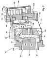
- FIGS. 2 through 7 illustrate details of a preferred embodiment of cell 10.
- cell 10 is, generally speaking, of the Herriott type, however with significant and important changes, innovations, and improvements.
- FIG. 3 is a cross-sectional view showing the basic construction of cell 10. This figure shows a structure providing first mirror 44 and second mirror 46.
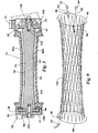
- a unique feature of cell 10 as seen in FIGS. 2, 3, 5 and 6 is the employment of a central axle member 74 having a first end 76 that engages first mirror 44 and a second end 77 that engages second mirror 46.
- the exterior surface 78 of central axle 74 is contoured, that is -- of less diameter in the middle than at the ends 76 and 77 for purposes, which will be described subsequently.
- housing 80 Surrounding central axle 74 is a housing 80 that, in the illustrated arrangement, as shown in FIG. 4, is formed of two matching portions 80A and 80B that fit together. Housing 80A, 80B provides an interior surface 82 spaced from the central axle external surface 78 providing an elongated annular area 84. It is this annular area 84 through which sample gas moves that absorption of light from the laser diode takes place and by which the concentration ofmethane in the gas sample is detected.
- first mirror 44 There is formed in first mirror 44 a first aperture 30 as seen in FIG. 2.
- Light beam 12 from laser diode 14 first passes through a lens 86 mounted in an opening in a lens support plate 89 and encounters an inclined window 88. At window 88 a portion of beam 12 is reflected to provide the laser beam 12B that was discussed with reference to FIG. 1.
- Beam 12B passing through a lens 90 and encounters first photo detector 32. Beam 12 passes through inclined window 88 and through first aperture 30 in first mirror 44.
- second mirror 46 has aperture 48 as previously mentioned that is in alignment with a passageway 92 in a cap member 94 by which the beam exits from the cell.
- photo detector 52 described with respect to FIG. 1.
- aperture 30 in first mirror 44 and apertures 48 in second mirror 46 are shown as if they are in a vertical plane taken through a longitudinal axis (not shown) of axle 76. This is for purposes of illustration only as there is no requirement that they be in the same plane and as seen in FIG. 9, which will now be discussed, apertures 30 and 48 are typically not in the same plane.
- FIG. 9 The pattern of light travel of the beam-entering cell 10 is illustrated in FIG. 9 wherein the first mirror 44 and second mirror 46 are represented by circles with smaller circles indicating first aperture 30 and second aperture 48.
- Laser diode indicated at 14 produces laser beam 12A as previously described that passes through first aperture 30 into the cell.
- Beam 12A strikes second mirror 46.
- a portion of beam 12A passes through second mirror 46 producing beam 62 that strikes third photo detector 64.
- the major portion of beam 12A is reflected as indicated by arrow 96.
- the beam travels back and forth between mirrors 44 and 46 a large number of times and finally exits through aperture 48 in second mirror 46, the exiting beam being indicated by numeral 50 described with respect to FIG. 1.
- Beam 50 strikes second photo detector 52.
- FIG. 9 graphically illustrates the unique beam path that travels a plurality of times back and fourth between mirrors 44 and 46 within the annular area that surrounds the central axle.
- This arrangement provides a very rigid cell structure having an extremely long path through which the laser beam travels through the annular area that is continuously supplied with sample gas.
- This long path achieved by multiple reflections of the light beam, provides for a high level of sensitivity of absorption of the laser beam while at the same time affords a compact, sturdy and easily portable system for detecting the presence of a selected gas, such as a methane.
- Laser diode 14 is supported by a laser mount structure generally indicated by the numeral 98 as seen in FIGS. 4, 5, 6 and 7.
- a different laser mount structure 98A is shown in FIGS. 2 and 11.
- FIG. 7 is an exploded view of important portions of laser mounting structure 98 that is supported to one end of cell 10 by means of structural brackets 100 shown in FIGS. 4 and 5.
- the laser mounting structure 98 includes a support base 102 having integrally formed parallel portions 104 and 106. That is, the support base includes integrally formed portion 104 that is hinged to base 102 about a vertical axis while portion 106 is integrally hinged to portion 104 about a horizontal axis.
- This unique double axis arrangement permits the alignment of the beam from the laser diode to be very accurately adjusted to provide the critical paths as illustrated in FIG. 9 so that the multiple paths can be accomplished and so the beam properly exits the cell to intersect photo diodes 52 and 64.
- An alternate embodiment of the double axis beam alignment system of this invention will be described subsequently with reference to FIGS. 2 and 11.
- an exchanger piece 108 has an integral forwardly extending plug portion 110.
- Exchanger piece 108 is secured to support base 102 by a spatial ring 112.
- a non-metallic isolator 114 Positioned on the forward surface of exchanger piece 108 is a non-metallic isolator 114.
- mounted on the forward surface 116 of the exchanger piece plug portion 110 is a peltier device 118, a substrate 120, a thermistor 122 and laser diode 14.
- the structure relationships between metallic drain 110, peltier 118, substrate 120, thermistor 122 and diode 14 are diagrammatically illustrated in FIG. 8.
- the rearward end of exchange piece 108 includes an integral tubular portion 124 that contains therein heat exchange fins 126 (See FIGS. 7 and 8).
- a resister 128 In a heat conductive relationship with plug portion 110, which functions as a metallic heat drain, is a resister 128 as shown in FIG. 8.
- An important aspect of the invention is the method and system for controlling the temperature of laser diode 14.
- a laser diode can be designed to provide the frequency of light that is most readily absorbed by methane molecules. However, if the frequency varies from the critical absorption frequency the accuracy of the system is reduced. Further, the frequency of light emitted by a laser diode is affected by the temperature of the diode.
- the system of this invention for controlling the temperature of laser diode 14 is best illustrated in FIGS. 8 and 10.
- FIG. 10 diagrammatically shows the relationship between laser diode 14 and its heat control components.
- Laser diode 14 is secured to a substrate 120 such as by the application of thermo-transmitting adhesive. Also secured to substrate 120 is a thermistor 122. Substrate 120 is bonded to a peltier element 118 that functions as a thermoelectric cooling element. Peltier 118 is thermally bonded such as by soldering, to a metallic drain 110 that is the plug portion of exchanger piece 108 as seen in FIG. 7. The metallic drain in turn is in thermal contact with one or more heat exchanger fins 126 as seen in FIGS. 2, 7 and 8. Also, in thermal contact with metallic drain 110 is a resistor 128 as seen in FIG. 8 and in the electrical diagram of FIG. 10.
- Thermistor 122 provides a voltage signal proportional to the temperature of substrate 120, which in turn is linked to the temperature of laser diode 14.
- a signal from thermistor 122 is fed to current generator circuit 130 and the signal from generator 130 is fed to an analog to digital converter 132, the output of which is passed to a microprocessor 138.
- a temperature selector circuit 136 provides a voltage output directly related to the desired temperature of the substrate 120 and therefore of laser diode 14, the output of which is fed to a microprocessor 138.
- microprocessor 138 the signal from the temperature selector circuit 136 is compared with the digitally encoded temperature detected by thermistor 122 to provide an output control signal on conductor 140.
- the signal on conductor 140 is fed to a heat mode on/off switch 142. When switch 142 is "on” this signal is fed to resistor 128 whose function is to supply heat as required to the heat exchanger plug portion 110.
- microprocessor 138 The output from microprocessor 138 is fed to a peltier control signal generator 144 that in turn is fed to a digital to analog converter 146, the output of which is fed to a peltier current generator 148 which in turn supplies a control current to peltier element 118.
- the function of the heat exchanger system of the invention is to cool laser diode 14. That is, laser diodes typically generate significant heat and therefore normally it is necessary to remove heat from the laser diode to keep it within the desired operating range. For this reason under normal operating conditions resistor 128 is not employed since its only function is to supply heat when necessary to the plug portion heat exchanger 110 so that by means of peltier 118 the heat is transferred to substrate 120 and thereby functions to provide a warm environment for laser diode 14.
- test gas As shown in FIG. 1 the test gas, after having passed through cell 10 is conducted to thermo regulating system 16 that is illustrated in FIGS. 8 and 10 and the elements of which are also illustrated in FIG. 7. Test gas that is moved through cell 10 in which the concentration of methane is determined, also advantageously is used as a cooling medium. The test gas passes out of cell 10 through the cooling system and past cooling fins 126 contained within housing tubular portion 124 as illustrated in FIG. 7 and diagrammatically in FIG. 8.
- the current consumed by a laser diode at selected voltages can be used as an indicator of the diode's temperature. That is, as the temperature of a laser diode increases the resistance to current flow increases. This characteristic can be used as a means of regulating the diode's temperature.
- the temperature control system disclosed in FIGS. 8 and 10 can be employed.
- an ammeter in series with laser diode 14 can be used to supply a control signal to measurement current generator 130 to produce an appropriate signal that is fed to A/D converter 132 and thence to microprocessor 138.
- the microprocessor directs temperature corrective action by peltier device 118 or resistor128. While this system has good theoretical possibilities, as a practical matter, achieving the required accuracy of diode temperature control using diode voltage and current has been difficult.
- sample gas entering and exiting cell 10 is illustrated best by reference to FIG. 3 in conjunction with FIG. 1.
- the gas enters cell 10 through a passageway 150 shown in dotted outline in cap member 94.
- passage 150 gas enters into an axial recess 152 in the second end 77 of central axle 74.
- a plurality of spaced apart small diameter passageways 154 extend in radial planes from axial recess 152 to the surface 78 of axle 74 to connect with annular absorption area 84.
- the plurality of openings 154 serve to equally distribute the sample gas entry into one end of absorption area 84.
- the gas traverses within absorption area 84 from the second end 77 to the first end 76 of axle 74.
- Adjacent the first end 76 of axle 74 are a plurality of passageways 156 in radial planes that communicate with an axial recess 158.
- Communicating with axial recess 158 is an exit passageway 160 by which sample gas flows from cell 10.
- the plurality of small passageways 156 that connect axial recess 158 to annular absorption area 84 are seen in FIGS. 2 and 3.
- Sample gas after passing out of cell 10 through exit passageway 160 flows through a length of flexible tubing 162 (see FIG. 5).
- Closing the rearward end of exchanger piece 108 is an end cap 164 that has a radial passageway 166 that receives an end of flexible tube 162 as shown in FIG. 5.
- a second passageway 168 in cap 164 (see FIG. 7) provides for communication with gas pump 26 as seen in FIG. 1 which can be accomplished such as by a flexible tube 170 illustrated in FIG. 1, but not shown on the other figures.
- Sample gas is drawn by the action of pump 26 to move into annular absorption area 84 in a way that the gas is equally distributed around the entire annular passageway so that as a light beam is bounced repeatedly between opposed mirrors 44 and 46, the opportunity for absorption of the light beam is equally distributed and in an arrangement wherein gas passageways are most effectively formed within the end portions of axle 74.
- the cell for measuring the concentration of a preselected gas, such as methane as illustrated and described herein is generally configured to operate at or near atmospheric pressures however the system functions successfully in the range of about .1 to about 2.0 atmospheres. Basically, the system as illustrated is not intended to test high-pressure gas samples.
- the gas detecting system of this invention is particularly adaptable for use in conducting a survey of a geographical area to find where gas leakage may be occurring.
- the gas detection system herein is particularly adapted for use as a survey instrument due to the confined annular absorption area that is achieved by the use of a center axle 74 surrounded by housing components 80A and 80B resulting in a relatively small volume sample gas test area having a relatively long path for a light beam to pass. Sample gas within the test area is quickly changed by the continuous action of gas pump 26.
- the gas detection system of this invention can be moved about by a moving vehicle at a speed that enables a relatively large geographical area to be checked for possible gas leakage in a relatively short time.
- sample gas inlet 18 as seen in FIG. 1 be extended exteriorly of the vehicle so that gas is constantly drawn into the system from the local environment as the vehicle moved from one part of a geographical area to another.
- the system of this invention is particularly adaptable for use with a global positioning system 172 as indicated in FIG. 1.
- Global positioning system 172 is in communication with microprocessor 42.
- a printer 174 coupled to microprocessor 42 and global positioning system 172, a map can be generated with a printout of detected gas concentration levels.
- a user can survey an area, such as a plant site, a village, an industrial park, a portion of a larger city, or any area of interest, and obtain a map with indicated levels concentration of a specific gas, such as methane. In this way, a user can quickly determine the areas where increased gas concentration exists and the instrument of this invention can then be returned to that area where it can be carried about (as opposed to being transported in a vehicle) for more detailed inspection to determine where gas leaks are occurring.
- FIGS. 2 and 11 show an alternate embodiment of a laser mount structure 98A that has a different double axis arrangement for alignment of the beam from the laser diode.
- a structural bracket 176 is secured to the forward end of cell 10. Bracket 176 supports a base plate 178 (see FIG. 11).
- An adjustable plate 180 is hinged to base plate 178 by a thin, flexible, first hinge sheet 182.
- a second thin, flexible, hinge sheet 184 supports exchange piece 186 having a tubular portion 188 that functions as a heat exchange housing, the outer end of which is closed by an end cover 190.
- Tubular portion 188 houses heat exchange fins 126.
- Tubular portion 188 has passageways 166A and 168A for the flow of sample gas corresponding to passageways 166 and 168 as described with reference to FIG. 7.
- the hinge sheets 182 and 184 bend within their elastic limits as the laser beam is aligned with cell 10 and therefore serve the same function as the integrally formed hinges of parallel portions 104 and 106 of support plate 102 as described with reference to FIG. 7. Both structures permit the laser diode to pivot about axii that are in perpendicular planes.
- the laser mount structure 98A of FIGS. 2 and 11 is preferred to the laser mount structure of FIG. 7 due to its economy of manufacture. Otherwise, the two embodiments function the same way to do the same thing and achieve the same results.
Landscapes
- Physics & Mathematics (AREA)
- Spectroscopy & Molecular Physics (AREA)
- General Physics & Mathematics (AREA)
- Biochemistry (AREA)
- Chemical & Material Sciences (AREA)
- Analytical Chemistry (AREA)
- Life Sciences & Earth Sciences (AREA)
- General Health & Medical Sciences (AREA)
- Health & Medical Sciences (AREA)
- Immunology (AREA)
- Pathology (AREA)
- Optics & Photonics (AREA)
- Investigating Or Analysing Materials By Optical Means (AREA)
Priority Applications (1)
| Application Number | Priority Date | Filing Date | Title |
|---|---|---|---|
| DE2002616988 DE60216988T2 (de) | 2002-09-06 | 2002-09-06 | Verfahren und Vorrichtung zur Gasdetektion mittels Absorptionsspektroskopie |
Applications Claiming Priority (1)
| Application Number | Priority Date | Filing Date | Title |
|---|---|---|---|
| PCT/US2002/028377 WO2004023114A1 (fr) | 2002-09-06 | 2002-09-06 | Procede et dispositif de detection de gaz par spectroscopie d'absorption |
Related Parent Applications (1)
| Application Number | Title | Priority Date | Filing Date |
|---|---|---|---|
| EP02778230A Division EP1535047B1 (fr) | 2002-09-06 | 2002-09-06 | Procede de detection de gaz par spectroscopie d'absorption |
Publications (3)
| Publication Number | Publication Date |
|---|---|
| EP1647820A2 true EP1647820A2 (fr) | 2006-04-19 |
| EP1647820A3 EP1647820A3 (fr) | 2006-05-03 |
| EP1647820B1 EP1647820B1 (fr) | 2006-12-20 |
Family
ID=31975586
Family Applications (2)
| Application Number | Title | Priority Date | Filing Date |
|---|---|---|---|
| EP06000797A Expired - Lifetime EP1647820B1 (fr) | 2002-09-06 | 2002-09-06 | Procédé et dispositif de détection de gaz par spectroscopie d'absorption |
| EP02778230A Expired - Lifetime EP1535047B1 (fr) | 2002-09-06 | 2002-09-06 | Procede de detection de gaz par spectroscopie d'absorption |
Family Applications After (1)
| Application Number | Title | Priority Date | Filing Date |
|---|---|---|---|
| EP02778230A Expired - Lifetime EP1535047B1 (fr) | 2002-09-06 | 2002-09-06 | Procede de detection de gaz par spectroscopie d'absorption |
Country Status (8)
| Country | Link |
|---|---|
| EP (2) | EP1647820B1 (fr) |
| CN (2) | CN100464178C (fr) |
| AT (1) | ATE434757T1 (fr) |
| AU (1) | AU2002339891A1 (fr) |
| BR (1) | BR0211327A (fr) |
| DE (1) | DE60232749D1 (fr) |
| ES (1) | ES2328800T3 (fr) |
| WO (1) | WO2004023114A1 (fr) |
Cited By (7)
| Publication number | Priority date | Publication date | Assignee | Title |
|---|---|---|---|---|
| US20110164251A1 (en) * | 2010-01-04 | 2011-07-07 | University Corporation For Atmospheric Research | Optical multi-pass cell |
| US8237926B2 (en) | 2008-10-29 | 2012-08-07 | Mitsubishi Heavy Industries, Ltd. | Method and apparatus for measuring density |
| DE102014013028A1 (de) | 2013-09-09 | 2015-03-26 | Huberg Kg - Huber Guenther & Co. | Messgerät zur Konzentrationsmessung einer Gasmischung |
| WO2015044020A3 (fr) * | 2013-09-24 | 2015-05-21 | Ge Healthcare Bio-Sciences Ab | Système de moniteur d'absorption optique |
| US10113955B2 (en) | 2015-11-25 | 2018-10-30 | Unisearch Associates Inc. | Gas cell for absorption spectroscopy |
| EP2993461B1 (fr) * | 2014-09-07 | 2019-12-18 | Unisearch Associates Inc. | Ensemble de cellules de gaz pour la spectroscopie d'absorption |
| GB2578920A (en) * | 2018-11-14 | 2020-06-03 | Duvas Tech Limited | Lighting arrangement for fluid analysis system |
Families Citing this family (64)
| Publication number | Priority date | Publication date | Assignee | Title |
|---|---|---|---|---|
| US7352463B2 (en) | 2002-09-06 | 2008-04-01 | Tdw Delaware, Inc. | Method and device for detecting gases by absorption spectroscopy |
| DE502005006303D1 (de) * | 2004-03-23 | 2009-02-05 | Koenig & Bauer Ag | Druckmaschine mit einem Inline-Inspektionssystem |
| JP4511857B2 (ja) | 2004-03-24 | 2010-07-28 | 国立大学法人京都大学 | フォトニック結晶を応用したセンサおよび検出対象物質の検出方法 |
| CN101021474B (zh) * | 2006-12-05 | 2010-09-01 | 中国科学院安徽光学精密机械研究所 | 开放式气体多组分监测仪及监测方法 |
| US8233150B2 (en) | 2006-12-12 | 2012-07-31 | Koninklijke Philips Electronics N.V. | Sample concentration detector with temperature compensation |
| ITBO20070036A1 (it) * | 2007-01-23 | 2008-07-24 | Aea Srl | Metodo e dispositivo di misura della concentrazione dei gas di scarico di una caldaia |
| EP1972922A1 (fr) * | 2007-03-22 | 2008-09-24 | S.I.T. S.r.l. | Cellule à passages multiples de type herriott de longueur variable |
| US8992836B2 (en) | 2008-11-14 | 2015-03-31 | Cornell University | Cavity-enhanced on-chip absorption spectroscopy |
| CN102128804B (zh) * | 2010-11-12 | 2013-06-19 | 上海芯敏微系统技术有限公司 | 一种侧壁进/出气的红外气体传感器 |
| US8531659B2 (en) * | 2011-03-24 | 2013-09-10 | The Laser Sensing Company | Multipass cell using spherical mirrors while achieving dense spot patterns |
| CN102297838B (zh) * | 2011-05-17 | 2013-07-31 | 西安交通大学 | 一种双锥形气体在线光谱分析气室 |
| CN102297839B (zh) * | 2011-05-20 | 2013-06-05 | 中国科学院电工研究所 | 一种用于吸收光谱测定的气体吸收池 |
| CN102495018B (zh) * | 2011-11-14 | 2012-10-17 | 济南火哨安全科技有限公司 | 温补一体红外吸收式气体传感器及检测装置 |
| CN103323423A (zh) * | 2013-05-24 | 2013-09-25 | 深圳市赛宝伦计算机技术有限公司 | 基于激光对气体浓度分析的抗干扰方法及系统 |
| US9109951B2 (en) * | 2013-11-06 | 2015-08-18 | Spectrasensors, Inc. | Reduced volume spectroscopic sample cell |
| DE102014000651B3 (de) | 2014-01-17 | 2015-05-13 | Gottfried Wilhelm Leibniz Universität Hannover | Vorrichtung zum Bestimmen einer Konzentration eines chemischen Stoffes |
| US10925515B2 (en) | 2014-05-22 | 2021-02-23 | Picomole Inc. | Alveolar breath collection apparatus |
| CN104483269A (zh) * | 2014-12-12 | 2015-04-01 | 东北石油大学 | 天然气吸收光谱测试用光学腔 |
| CN104535531A (zh) * | 2014-12-15 | 2015-04-22 | 北京航天易联科技发展有限公司 | 手持激光气体浓度监测仪及其控制方法 |
| GB2538563B (en) * | 2015-05-22 | 2017-08-02 | Optosci Ltd | Gas sensing apparatus |
| FR3040528B1 (fr) * | 2015-09-02 | 2017-09-15 | Pfeiffer Vacuum Sas | Procede et station de mesure de la contamination d'une boite de transport pour le convoyage et le stockage atmospherique de substrats |
| US10724945B2 (en) | 2016-04-19 | 2020-07-28 | Cascade Technologies Holdings Limited | Laser detection system and method |
| US10180393B2 (en) | 2016-04-20 | 2019-01-15 | Cascade Technologies Holdings Limited | Sample cell |
| US10775297B2 (en) | 2016-08-24 | 2020-09-15 | Ecotec Solutions, Inc. | Laser absorption spectroscopy system and method for discrimination of a first and a second gas |
| GB201700905D0 (en) | 2017-01-19 | 2017-03-08 | Cascade Tech Holdings Ltd | Close-Coupled Analyser |
| CN106770026A (zh) * | 2017-01-23 | 2017-05-31 | 章欣 | 光学气体吸收池及光学气体传感器 |
| CN106596468A (zh) * | 2017-01-23 | 2017-04-26 | 章欣 | 光学气体吸收池及光学气体传感器 |
| CN108398387A (zh) * | 2017-02-07 | 2018-08-14 | 上海艾梦电子科技有限公司 | 一种基于光谱的no浓度检测仪 |
| CA2998026A1 (fr) | 2017-03-13 | 2018-09-13 | Picomole Inc. | Appareil et methode d'optimisation de systeme laser |
| CN108279215B (zh) * | 2017-12-26 | 2023-09-05 | 聚光科技(杭州)股份有限公司 | 光电式气体检测装置及其工作方法 |
| CN108132182A (zh) * | 2018-01-25 | 2018-06-08 | 中国科学院半导体研究所 | 一种加热混合气体的结构 |
| US12071608B2 (en) * | 2018-02-28 | 2024-08-27 | Rosemount Inc. | Detachable dissolved oxygen sensor interface for single-use bioreactor/mixer |
| US12216105B2 (en) | 2018-06-19 | 2025-02-04 | Seekops Inc. | Localization analytics algorithms and methods |
| WO2019246280A1 (fr) | 2018-06-19 | 2019-12-26 | Seekops Inc. | Algorithmes et procédés de modèle d'estimation d'émissions |
| US12399164B2 (en) | 2018-06-19 | 2025-08-26 | Seekops Inc. | Emissions estimate model algorithms and methods |
| US12044666B2 (en) * | 2018-07-30 | 2024-07-23 | Seekops Inc. | Ultra-lightweight, handheld gas leak detection device |
| WO2020086499A1 (fr) | 2018-10-22 | 2020-04-30 | Seekops Inc. | Capteur ponctuel léger à bande passante élevée embarqué sur uav pour quantifier des gaz à effet de serre dans des strates atmosphériques |
| CN109520931A (zh) * | 2018-12-29 | 2019-03-26 | 青岛海纳光电环保有限公司 | 气体吸收室 |
| CN109856054A (zh) * | 2019-03-26 | 2019-06-07 | 北京市燃气集团有限责任公司 | 一种腔衰荡光谱的检测装置 |
| US11035789B2 (en) | 2019-04-03 | 2021-06-15 | Picomole Inc. | Cavity ring-down spectroscopy system and method of modulating a light beam therein |
| US12188847B2 (en) | 2019-04-05 | 2025-01-07 | Seekops Inc. | Time-and data-efficient assurance of leak detection |
| CN110057452A (zh) * | 2019-05-16 | 2019-07-26 | 北京印刷学院 | 光谱检测装置及系统 |
| CN110361353B (zh) * | 2019-08-15 | 2024-11-08 | 深圳市诺安智能股份有限公司 | 具有自适应反光件的气体浓度检测装置及报警装置 |
| US11553814B2 (en) * | 2019-08-28 | 2023-01-17 | Ii-Vi Delaware, Inc. | Non-electric powered, off-grid, beverage brewer |
| CN110426353B (zh) * | 2019-09-09 | 2024-07-23 | 中国空气动力研究与发展中心超高速空气动力研究所 | 一种气体激光吸收光谱测量的标定装置 |
| US12392680B2 (en) | 2019-09-20 | 2025-08-19 | Seekops Inc. | Spectral fitting of compact laser-based trace gas sensor measurements for high dynamic range (HDR) |
| EP4038357A4 (fr) | 2019-10-04 | 2023-11-08 | SeekOps Inc. | Génération de circuit de vol à surface fermée pour évaluation de plan des flux de véhicules aériens sans pilote (vasp) |
| US11614430B2 (en) | 2019-12-19 | 2023-03-28 | Seekops Inc. | Concurrent in-situ measurement of wind speed and trace gases on mobile platforms for localization and qualification of emissions |
| CN111157470A (zh) * | 2020-01-06 | 2020-05-15 | 武汉米字能源科技有限公司 | 一种多激光器同时在线测量多组分气体含量的方法 |
| WO2021158916A1 (fr) | 2020-02-05 | 2021-08-12 | Seekops Inc. | Cellule optique à trajet optique multiple pour la mesure de gaz à l'état de trace |
| US12055485B2 (en) | 2020-02-05 | 2024-08-06 | Seekops Inc. | Multispecies measurement platform using absorption spectroscopy for measurement of co-emitted trace gases |
| US11782049B2 (en) | 2020-02-28 | 2023-10-10 | Picomole Inc. | Apparatus and method for collecting a breath sample using a container with controllable volume |
| US11957450B2 (en) | 2020-02-28 | 2024-04-16 | Picomole Inc. | Apparatus and method for collecting a breath sample using an air circulation system |
| CN111458299B (zh) * | 2020-04-30 | 2025-03-25 | 武汉六九传感科技有限公司 | 一种气体吸收池、气体浓度检测装置及方法 |
| CN111474130A (zh) * | 2020-05-29 | 2020-07-31 | 南昌航空大学 | 一种基于光谱法在线检测气态丙醛、丙烯醛的简便装置及方法 |
| CN111562228A (zh) * | 2020-06-15 | 2020-08-21 | 合肥中光环象光电科技有限公司 | 一种二氧化氮测量装置及测量方法 |
| WO2022016107A1 (fr) | 2020-07-17 | 2022-01-20 | Seekops Inc. | Pratique de travail en uas |
| US11748866B2 (en) | 2020-07-17 | 2023-09-05 | Seekops Inc. | Systems and methods of automated detection of gas plumes using optical imaging |
| CN112304898B (zh) * | 2020-10-23 | 2023-03-24 | 西安智光物联科技有限公司 | 一种车载前置式激光气体检测仪 |
| WO2022093864A1 (fr) | 2020-10-27 | 2022-05-05 | Seekops Inc. | Procédés et appareil pour mesurer des émissions de méthane avec un capteur optique de méthane à cavité ouverte |
| US12345595B2 (en) * | 2021-10-27 | 2025-07-01 | Ii-Vi Delaware, Inc. | Eye safety interlock for fiber-coupled high power laser sources |
| US12504369B1 (en) | 2022-11-04 | 2025-12-23 | Ecotec Solutions, Inc. | Vertical emissions monitoring manifold |
| CN116973326A (zh) * | 2023-08-07 | 2023-10-31 | 宁波海尔欣光电科技有限公司 | 一种同时测量多种气体浓度的便携式低功耗仪器 |
| CN120232816B (zh) * | 2025-06-03 | 2025-08-22 | 吉林大学 | 一种中空圆台形多通吸收池 |
Family Cites Families (6)
| Publication number | Priority date | Publication date | Assignee | Title |
|---|---|---|---|---|
| US5414264A (en) * | 1993-04-16 | 1995-05-09 | Gaztech International Corporation | Enhanced pathlength gas sample chamber |
| GB2286458A (en) * | 1994-02-04 | 1995-08-16 | Marconi Gec Ltd | An optical absorption oxygen sensor |
| FR2733319B1 (fr) * | 1995-04-21 | 1997-05-23 | Air Liquide | Procede et dispositif d'analyse de traces d'impuretes dans un echantillon de gaz au moyen d'une diode laser |
| US5977546A (en) * | 1997-05-13 | 1999-11-02 | Carlson; Lee Richard | Self normalizing radiant energy monitor and apparatus for gain independent material quantity measurements |
| CN2303293Y (zh) * | 1997-06-04 | 1999-01-06 | 侯蓝田 | 气体浓度检测装置 |
| US6421127B1 (en) * | 1999-07-19 | 2002-07-16 | American Air Liquide, Inc. | Method and system for preventing deposition on an optical component in a spectroscopic sensor |
-
2002
- 2002-09-06 CN CNB028295315A patent/CN100464178C/zh not_active Expired - Fee Related
- 2002-09-06 ES ES02778230T patent/ES2328800T3/es not_active Expired - Lifetime
- 2002-09-06 DE DE60232749T patent/DE60232749D1/de not_active Expired - Lifetime
- 2002-09-06 AT AT02778230T patent/ATE434757T1/de not_active IP Right Cessation
- 2002-09-06 AU AU2002339891A patent/AU2002339891A1/en not_active Abandoned
- 2002-09-06 CN CN2009100001130A patent/CN101470072B/zh not_active Expired - Fee Related
- 2002-09-06 WO PCT/US2002/028377 patent/WO2004023114A1/fr not_active Ceased
- 2002-09-06 EP EP06000797A patent/EP1647820B1/fr not_active Expired - Lifetime
- 2002-09-06 BR BR0211327-9A patent/BR0211327A/pt not_active IP Right Cessation
- 2002-09-06 EP EP02778230A patent/EP1535047B1/fr not_active Expired - Lifetime
Cited By (11)
| Publication number | Priority date | Publication date | Assignee | Title |
|---|---|---|---|---|
| US8237926B2 (en) | 2008-10-29 | 2012-08-07 | Mitsubishi Heavy Industries, Ltd. | Method and apparatus for measuring density |
| US20110164251A1 (en) * | 2010-01-04 | 2011-07-07 | University Corporation For Atmospheric Research | Optical multi-pass cell |
| US8508740B2 (en) * | 2010-01-04 | 2013-08-13 | University Corporation For Atmospheric Research | Optical multi-pass cell |
| DE102014013028A1 (de) | 2013-09-09 | 2015-03-26 | Huberg Kg - Huber Guenther & Co. | Messgerät zur Konzentrationsmessung einer Gasmischung |
| WO2015044020A3 (fr) * | 2013-09-24 | 2015-05-21 | Ge Healthcare Bio-Sciences Ab | Système de moniteur d'absorption optique |
| US20160231232A1 (en) * | 2013-09-24 | 2016-08-11 | Ge Healthcare Bio-Sciences Ab | Optical absorption monitor system |
| JP2016530546A (ja) * | 2013-09-24 | 2016-09-29 | ジーイー・ヘルスケア・バイオサイエンス・アクチボラグ | 光吸収モニタシステム |
| US9880093B2 (en) * | 2013-09-24 | 2018-01-30 | Ge Healthcare Bio-Sciences Ab | Optical absorption monitor system |
| EP2993461B1 (fr) * | 2014-09-07 | 2019-12-18 | Unisearch Associates Inc. | Ensemble de cellules de gaz pour la spectroscopie d'absorption |
| US10113955B2 (en) | 2015-11-25 | 2018-10-30 | Unisearch Associates Inc. | Gas cell for absorption spectroscopy |
| GB2578920A (en) * | 2018-11-14 | 2020-06-03 | Duvas Tech Limited | Lighting arrangement for fluid analysis system |
Also Published As
| Publication number | Publication date |
|---|---|
| CN101470072A (zh) | 2009-07-01 |
| EP1535047B1 (fr) | 2009-06-24 |
| CN101470072B (zh) | 2011-02-16 |
| BR0211327A (pt) | 2004-12-21 |
| ATE434757T1 (de) | 2009-07-15 |
| EP1535047A1 (fr) | 2005-06-01 |
| ES2328800T3 (es) | 2009-11-18 |
| WO2004023114A1 (fr) | 2004-03-18 |
| CN1659428A (zh) | 2005-08-24 |
| AU2002339891A1 (en) | 2004-03-29 |
| DE60232749D1 (de) | 2009-08-06 |
| EP1647820A3 (fr) | 2006-05-03 |
| CN100464178C (zh) | 2009-02-25 |
| EP1647820B1 (fr) | 2006-12-20 |
Similar Documents
| Publication | Publication Date | Title |
|---|---|---|
| EP1647820B1 (fr) | Procédé et dispositif de détection de gaz par spectroscopie d'absorption | |
| US7352463B2 (en) | Method and device for detecting gases by absorption spectroscopy | |
| US5734165A (en) | Microstructured infrared absorption photometer | |
| US9784674B2 (en) | Analytes monitoring by differential swept wavelength absorption spectroscopy methods | |
| US6635875B1 (en) | Infrared gas analyzer and method for operating said analyzer | |
| KR101098124B1 (ko) | 멀티가스 감시 및 검출 시스템 | |
| CN105628637B (zh) | 一种三参考通道的红外气体分析方法与装置 | |
| Silver et al. | Diode laser measurements of concentration and temperature in microgravity combustion | |
| Cui et al. | Photonic sensing of the atmosphere by absorption spectroscopy | |
| CN108007901B (zh) | 一种检测多组分痕量气体浓度的方法与装置 | |
| US20180059003A1 (en) | Laser absorption spectroscopy system and method for discrimination of a first and a second gas | |
| US7248357B2 (en) | Method and apparatus for optically measuring the heating value of a multi-component fuel gas using nir absorption spectroscopy | |
| Weigl et al. | Photoacoustic detection of acetone in N2 and synthetic air using a high power UV LED | |
| CN101595375A (zh) | 泄漏检测系统和方法 | |
| CN118056123A (zh) | 在露天构造中经由激光吸收光谱来同时高灵敏度测量甲烷和乙烷的系统和方法 | |
| US7755767B2 (en) | Resonator-amplified absorption spectrometer | |
| US20250258092A1 (en) | Multi-gas sensing and detection system | |
| Phillips et al. | Standoff detection of turbulent chemical mixture plumes using a swept external cavity quantum cascade laser | |
| Yu et al. | Tunable diode laser absorption spectroscopy for open-path monitoring gas markers in fire combustion products | |
| Fang et al. | Highly sensitive portable laser absorption spectroscopy formaldehyde sensor using compact spherical mirror multi-pass cell | |
| Frish et al. | Standoff gas leak detectors based on tunable diode laser absorption spectroscopy | |
| Liu et al. | High-precision in situ sensor for methane isotope (δ13C) measurement based on the near-infrared off-axis integrated cavity output spectroscopy | |
| Zhang et al. | Rotating multi-channel high-sensitivity integrating sphere gas sensing based on NDIR | |
| CN206740638U (zh) | 一种并联式气体光谱分析双气室 | |
| Frish et al. | Handheld laser-based sensor for remote detection of toxic and hazardous gases |
Legal Events
| Date | Code | Title | Description |
|---|---|---|---|
| PUAI | Public reference made under article 153(3) epc to a published international application that has entered the european phase |
Free format text: ORIGINAL CODE: 0009012 |
|
| PUAL | Search report despatched |
Free format text: ORIGINAL CODE: 0009013 |
|
| 17P | Request for examination filed |
Effective date: 20060119 |
|
| AC | Divisional application: reference to earlier application |
Ref document number: 1535047 Country of ref document: EP Kind code of ref document: P |
|
| AK | Designated contracting states |
Kind code of ref document: A2 Designated state(s): AT BE BG CH CY CZ DE DK EE ES FI FR GB GR IE IT LI LU MC NL PT SE SK TR |
|
| AK | Designated contracting states |
Kind code of ref document: A3 Designated state(s): AT BE BG CH CY CZ DE DK EE ES FI FR GB GR IE IT LI LU MC NL PT SE SK TR |
|
| GRAP | Despatch of communication of intention to grant a patent |
Free format text: ORIGINAL CODE: EPIDOSNIGR1 |
|
| RIN1 | Information on inventor provided before grant (corrected) |
Inventor name: BOUNAIX, FABRICE MARCEL S |
|
| GRAS | Grant fee paid |
Free format text: ORIGINAL CODE: EPIDOSNIGR3 |
|
| GRAA | (expected) grant |
Free format text: ORIGINAL CODE: 0009210 |
|
| AC | Divisional application: reference to earlier application |
Ref document number: 1535047 Country of ref document: EP Kind code of ref document: P |
|
| AK | Designated contracting states |
Kind code of ref document: B1 Designated state(s): AT BE BG CH CY CZ DE DK EE ES FI FR GB GR IE IT LI LU MC NL PT SE SK TR |
|
| PG25 | Lapsed in a contracting state [announced via postgrant information from national office to epo] |
Ref country code: DK Free format text: LAPSE BECAUSE OF FAILURE TO SUBMIT A TRANSLATION OF THE DESCRIPTION OR TO PAY THE FEE WITHIN THE PRESCRIBED TIME-LIMIT Effective date: 20061220 Ref country code: CH Free format text: LAPSE BECAUSE OF FAILURE TO SUBMIT A TRANSLATION OF THE DESCRIPTION OR TO PAY THE FEE WITHIN THE PRESCRIBED TIME-LIMIT Effective date: 20061220 Ref country code: AT Free format text: LAPSE BECAUSE OF FAILURE TO SUBMIT A TRANSLATION OF THE DESCRIPTION OR TO PAY THE FEE WITHIN THE PRESCRIBED TIME-LIMIT Effective date: 20061220 Ref country code: BE Free format text: LAPSE BECAUSE OF FAILURE TO SUBMIT A TRANSLATION OF THE DESCRIPTION OR TO PAY THE FEE WITHIN THE PRESCRIBED TIME-LIMIT Effective date: 20061220 Ref country code: SK Free format text: LAPSE BECAUSE OF FAILURE TO SUBMIT A TRANSLATION OF THE DESCRIPTION OR TO PAY THE FEE WITHIN THE PRESCRIBED TIME-LIMIT Effective date: 20061220 Ref country code: NL Free format text: LAPSE BECAUSE OF FAILURE TO SUBMIT A TRANSLATION OF THE DESCRIPTION OR TO PAY THE FEE WITHIN THE PRESCRIBED TIME-LIMIT Effective date: 20061220 Ref country code: LI Free format text: LAPSE BECAUSE OF FAILURE TO SUBMIT A TRANSLATION OF THE DESCRIPTION OR TO PAY THE FEE WITHIN THE PRESCRIBED TIME-LIMIT Effective date: 20061220 |
|
| REG | Reference to a national code |
Ref country code: GB Ref legal event code: FG4D |
|
| AKX | Designation fees paid |
Designated state(s): AT BE BG CH CY CZ DE DK EE ES FI FR GB GR IE IT LI LU MC NL PT SE SK TR |
|
| REG | Reference to a national code |
Ref country code: CH Ref legal event code: EP |
|
| REF | Corresponds to: |
Ref document number: 60216988 Country of ref document: DE Date of ref document: 20070201 Kind code of ref document: P |
|
| REG | Reference to a national code |
Ref country code: IE Ref legal event code: FG4D |
|
| PG25 | Lapsed in a contracting state [announced via postgrant information from national office to epo] |
Ref country code: SE Free format text: LAPSE BECAUSE OF FAILURE TO SUBMIT A TRANSLATION OF THE DESCRIPTION OR TO PAY THE FEE WITHIN THE PRESCRIBED TIME-LIMIT Effective date: 20070320 Ref country code: BG Free format text: LAPSE BECAUSE OF FAILURE TO SUBMIT A TRANSLATION OF THE DESCRIPTION OR TO PAY THE FEE WITHIN THE PRESCRIBED TIME-LIMIT Effective date: 20070320 |
|
| PG25 | Lapsed in a contracting state [announced via postgrant information from national office to epo] |
Ref country code: ES Free format text: LAPSE BECAUSE OF FAILURE TO SUBMIT A TRANSLATION OF THE DESCRIPTION OR TO PAY THE FEE WITHIN THE PRESCRIBED TIME-LIMIT Effective date: 20070331 |
|
| PG25 | Lapsed in a contracting state [announced via postgrant information from national office to epo] |
Ref country code: PT Free format text: LAPSE BECAUSE OF FAILURE TO SUBMIT A TRANSLATION OF THE DESCRIPTION OR TO PAY THE FEE WITHIN THE PRESCRIBED TIME-LIMIT Effective date: 20070424 |
|
| ET | Fr: translation filed | ||
| NLV1 | Nl: lapsed or annulled due to failure to fulfill the requirements of art. 29p and 29m of the patents act | ||
| REG | Reference to a national code |
Ref country code: CH Ref legal event code: PL |
|
| PLBE | No opposition filed within time limit |
Free format text: ORIGINAL CODE: 0009261 |
|
| STAA | Information on the status of an ep patent application or granted ep patent |
Free format text: STATUS: NO OPPOSITION FILED WITHIN TIME LIMIT |
|
| 26N | No opposition filed |
Effective date: 20070921 |
|
| PG25 | Lapsed in a contracting state [announced via postgrant information from national office to epo] |
Ref country code: MC Free format text: LAPSE BECAUSE OF NON-PAYMENT OF DUE FEES Effective date: 20070930 Ref country code: GR Free format text: LAPSE BECAUSE OF FAILURE TO SUBMIT A TRANSLATION OF THE DESCRIPTION OR TO PAY THE FEE WITHIN THE PRESCRIBED TIME-LIMIT Effective date: 20070321 |
|
| PG25 | Lapsed in a contracting state [announced via postgrant information from national office to epo] |
Ref country code: IE Free format text: LAPSE BECAUSE OF NON-PAYMENT OF DUE FEES Effective date: 20070906 |
|
| PG25 | Lapsed in a contracting state [announced via postgrant information from national office to epo] |
Ref country code: EE Free format text: LAPSE BECAUSE OF FAILURE TO SUBMIT A TRANSLATION OF THE DESCRIPTION OR TO PAY THE FEE WITHIN THE PRESCRIBED TIME-LIMIT Effective date: 20061220 |
|
| PG25 | Lapsed in a contracting state [announced via postgrant information from national office to epo] |
Ref country code: FI Free format text: LAPSE BECAUSE OF FAILURE TO SUBMIT A TRANSLATION OF THE DESCRIPTION OR TO PAY THE FEE WITHIN THE PRESCRIBED TIME-LIMIT Effective date: 20061220 Ref country code: CY Free format text: LAPSE BECAUSE OF FAILURE TO SUBMIT A TRANSLATION OF THE DESCRIPTION OR TO PAY THE FEE WITHIN THE PRESCRIBED TIME-LIMIT Effective date: 20061220 Ref country code: LU Free format text: LAPSE BECAUSE OF NON-PAYMENT OF DUE FEES Effective date: 20070906 |
|
| PG25 | Lapsed in a contracting state [announced via postgrant information from national office to epo] |
Ref country code: TR Free format text: LAPSE BECAUSE OF FAILURE TO SUBMIT A TRANSLATION OF THE DESCRIPTION OR TO PAY THE FEE WITHIN THE PRESCRIBED TIME-LIMIT Effective date: 20061220 |
|
| PGFP | Annual fee paid to national office [announced via postgrant information from national office to epo] |
Ref country code: DE Payment date: 20130821 Year of fee payment: 12 Ref country code: CZ Payment date: 20130823 Year of fee payment: 12 |
|
| PGFP | Annual fee paid to national office [announced via postgrant information from national office to epo] |
Ref country code: FR Payment date: 20130821 Year of fee payment: 12 |
|
| REG | Reference to a national code |
Ref country code: DE Ref legal event code: R119 Ref document number: 60216988 Country of ref document: DE |
|
| PG25 | Lapsed in a contracting state [announced via postgrant information from national office to epo] |
Ref country code: CZ Free format text: LAPSE BECAUSE OF NON-PAYMENT OF DUE FEES Effective date: 20140906 |
|
| REG | Reference to a national code |
Ref country code: FR Ref legal event code: ST Effective date: 20150529 |
|
| PG25 | Lapsed in a contracting state [announced via postgrant information from national office to epo] |
Ref country code: DE Free format text: LAPSE BECAUSE OF NON-PAYMENT OF DUE FEES Effective date: 20150401 |
|
| PG25 | Lapsed in a contracting state [announced via postgrant information from national office to epo] |
Ref country code: FR Free format text: LAPSE BECAUSE OF NON-PAYMENT OF DUE FEES Effective date: 20140930 |
|
| REG | Reference to a national code |
Ref country code: GB Ref legal event code: 732E Free format text: REGISTERED BETWEEN 20170202 AND 20170208 |
|
| PGFP | Annual fee paid to national office [announced via postgrant information from national office to epo] |
Ref country code: IT Payment date: 20210811 Year of fee payment: 20 |
|
| PGFP | Annual fee paid to national office [announced via postgrant information from national office to epo] |
Ref country code: GB Payment date: 20210728 Year of fee payment: 20 |
|
| REG | Reference to a national code |
Ref country code: GB Ref legal event code: PE20 Expiry date: 20220905 |
|
| PG25 | Lapsed in a contracting state [announced via postgrant information from national office to epo] |
Ref country code: GB Free format text: LAPSE BECAUSE OF EXPIRATION OF PROTECTION Effective date: 20220905 |