EP1647879A2 - Dispositif de détection de position - Google Patents
Dispositif de détection de position Download PDFInfo
- Publication number
- EP1647879A2 EP1647879A2 EP05109321A EP05109321A EP1647879A2 EP 1647879 A2 EP1647879 A2 EP 1647879A2 EP 05109321 A EP05109321 A EP 05109321A EP 05109321 A EP05109321 A EP 05109321A EP 1647879 A2 EP1647879 A2 EP 1647879A2
- Authority
- EP
- European Patent Office
- Prior art keywords
- pointer
- sensor
- group
- order
- detecting device
- Prior art date
- Legal status (The legal status is an assumption and is not a legal conclusion. Google has not performed a legal analysis and makes no representation as to the accuracy of the status listed.)
- Granted
Links
Images



Classifications
-
- G—PHYSICS
- G06—COMPUTING OR CALCULATING; COUNTING
- G06F—ELECTRIC DIGITAL DATA PROCESSING
- G06F3/00—Input arrangements for transferring data to be processed into a form capable of being handled by the computer; Output arrangements for transferring data from processing unit to output unit, e.g. interface arrangements
- G06F3/01—Input arrangements or combined input and output arrangements for interaction between user and computer
- G06F3/03—Arrangements for converting the position or the displacement of a member into a coded form
- G06F3/041—Digitisers, e.g. for touch screens or touch pads, characterised by the transducing means
- G06F3/046—Digitisers, e.g. for touch screens or touch pads, characterised by the transducing means by electromagnetic means
Definitions
- the present invention relates to a position detecting device that detects a position pointed by a position pointer using electromagnetic or electrostatic coupling and that is used for an input device of an electronic apparatus, for example, a computer aided design (CAD) terminal, a computer, a personal digital assistant (PDA), a digital camera, a cell phone, and a personal handyphone system (PHS), or another mobile electronic appliance, in particular a mobile telecommunication device.
- CAD computer aided design
- PDA personal digital assistant
- PDA personal digital assistant
- PDA personal digital camera
- cell phone a cell phone
- PHS personal handyphone system
- Position detection devices have been used which receive an electromagnetic coupling signal from a position pointer for pointing a position so as to detect a position pointed by the position pointer and which are used for an input device of, for example, a CAD terminal, a computer, a PDA, and a cell phone (refer to, for example, Japanese Unexamined Patent Application Publication No. 8-44480).
- Fig. 6 is a timing diagram of a known position detecting device in which sensor coils are spatially arranged in an XY matrix. As shown in Fig. 6, if the known position detecting device has already recognized a position pointed by a position pointer, a predetermined number of X-axis direction sensor coils and a predetermined number of Y-axis direction sensor coils arranged in the vicinity of a position pointed by the position pointer (sensor coils 1 to 6 in Fig. 6) are alternatively scanned in a direction in which the sensors are arranged (i.e., a direction from the sensor coil 1 to the sensor coil 6) so that each of the sensor coils and the position pointer communicate signals.
- the sequence of selecting the sensor coils is given by the spatial arrangement, e.g. the selection proceeds in X or Y direction such that neighboring sensor coils are selected in a sequence going into one coordinate direction.
- the position detecting device detects the position pointing signals from the position pointer and computes the position pointed by the position pointer using, for example, parabolic approximation.
- each sensor coil transmits a detecting signal to the position pointer and receives a position pointing signal from the position pointer several times (four times in an example shown in Fig. 7) to compute the position pointed by the position pointer by using the sum or average value of signal levels obtained from the receiving operations.
- a position detecting device used at a position very close to the body of an electronic apparatus such as a computer and a PDA, has a disadvantage in that a significant error occurs when detecting a position pointed by a position pointer due to electromagnetic noise which is generated by the body of the electronic apparatus and which influences a signal received from the position pointer using electromagnetic coupling.
- noise in a driving signal of a liquid crystal display (LCD) incorporated in the body of the electronic apparatus (for example, noise in a display driving signal or in a backlight inverter) disadvantageously causes a significant detection error.
- LCD liquid crystal display
- a scanning frequency of the sensor coils in the position detecting device is close to a frequency of noise from the body of the electronic apparatus, that is, when the difference between both frequencies is small, low-frequency jitter is generated, since the sensor coils are scanned in the order in which the sensor coils are arranged. Thus, it is difficult to eliminate the influence of the noise. Consequently, the detected position may vary and a significant error may occur. Alternatively, the level of a signal detected by a specific sensor coil may be high, and therefore, the signal is detected as if the position of the position pointer is displaced. Thus, a detection error becomes large, which is a problem.
- Fig. 8 illustrates a frequency characteristic of jitter when an electromagnetic coupling signal received by a position pointing device from a position pointer is affected by noise generated by an LCD in an electronic apparatus.
- the unit interval of a sensor-coil scanning frequency is a reciprocal number 1/Ts of scanning time Ts for scanning two coils of the position detecting device (or one coil depending on a computing method of the coordinates of the position detecting device)
- a large low-frequency jitter occurs for noise at positions of a frequency distant from a sensor-coil scanning frequency f0 by ⁇ 0.5 frequencies, that is, at positions of f0 ⁇ 0.5/Ts. Accordingly, a large detection error disadvantageously occurs due to the noise.
- the present invention provides a position detecting device as claimed in claim 1. Preferred embodiments are given in the dependent claims.
- a position detecting device comprising
- Performing a selection of the position detection units in an order that differs from the spatial arrangement of the position detections units has the surprising effect that the signal to noise ratio can be improved thereby. For example, this reduces or eliminates the disturbance of the position detection caused by noise generated by a display driver or another noise source of an electronic apparatus in the vicinity of the position detecting device.
- At least first and second consecutive sequences are selected by the control means. Signals acquired due to the selection of the at least first and second consecutive sequences are used by the control means for determining the position.
- the at least first and second consecutive sequences differ from each other. Using consecutive sequences with varying orders of selection can further improve the signal to noise ratio.
- the present invention provides a position detecting device for reducing a detection error due to the influence of noise.
- a position detecting device includes a position pointer, a plurality of sensors arranged in a direction of detecting a position, reception means for receiving a position pointed by the position pointer using the sensors via electromagnetic coupling or electrostatic coupling, and detection means for detecting the position pointed by the position pointer from the received signal.
- the reception means extracts a predetermined number of sensors from among the plurality of sensors to form each of a plurality of groups and defines a unique order of selecting a sensor to be scanned for each group, and the order of selecting a sensor in a group to be scanned is different from that in the immediately previously scanned group.
- a position detecting device includes a plurality of sensors arranged in a predetermined order for receiving a signal from a position pointer; reception means for extracting a predetermined number of plural sensors from among the plurality of sensors to form each of a plurality of groups and receiving the signal from the position pointer using the sensors selected in a predetermined order from among the sensors in the group via electromagnetic coupling or electrostatic coupling; and detection means for detecting a position pointed by the position pointer on the basis of the signals received by the selected sensors.
- the reception means sequentially forms a plurality of groups in which an order of selecting the extracted sensors is different from each other and receives the signal from the position pointer for each group using the sensors selected according to the order defined for each group via electromagnetic coupling or electrostatic coupling.
- the detection means detects a position pointed by the position pointer on the basis of the signals received by the selected sensors.
- the reception means can select the sensors located at either side of the remaining sensors in each group prior to each of the middle sensors located between the two end sensors and receives a signal from the position pointer via electromagnetic coupling or electrostatic coupling.
- the reception means can change an order of selecting each of the middle sensors in each group in a predetermined manner so that the order of selecting the sensor is different for each group and receives a signal from the position pointer using the selected sensor via electromagnetic coupling or electrostatic coupling.
- the reception means can repeat a cycle of a set formed from a plurality of the groups each having a different order of selecting a sensor in the group.
- the detection means can detect tentative positions pointed by the position pointer on the basis of signals received by the sensors in each group and can determine the moving average of a predetermined number of the tentative positions to be the position pointed by the position pointer.
- the position detecting device can further include transmission means for delivering a position detecting signal to the sensors so as to cause the sensors to transmit a position detecting signal for detecting a position pointed by the position pointer to the position pointer via electromagnetic coupling or electrostatic coupling.
- the transmission means can select the same sensor as a reception sensor selected by the reception means and delivers the position detecting signal to the selected sensor.
- the position detecting device can further include transmission means for delivering a position detecting signal to the sensor so as to cause the sensor to transmit a position detecting signal for detecting a position pointed by the position pointer to the position pointer via electromagnetic coupling or electrostatic coupling.
- the transmission means can select the sensor located at a position closest to the position pointer in each group and delivers the position detecting signal to the selected sensor.
- a position detecting device includes a position pointer, a plurality of transmission units arranged in a direction of detecting a position, transmission means for transmitting a position pointed by the position pointer using the transmission units via electromagnetic coupling or electrostatic coupling, reception means for receiving signals transmitted from the transmission units, and detection means for detecting the position pointed by the position pointer from the received signal.
- the transmission means extracts a predetermined number of transmission units from among the plurality of transmission units in an order of the arrangement thereof to form each of a plurality of groups and defines a unique order of selecting a transmission unit to be scanned for each group and wherein the order of selecting the transmission units in a group to be scanned is different from that in the immediately previously scanned group.
- a position detecting device includes a plurality of transmission units arranged in a predetermined order for transmitting a position detecting signal to a position pointer using electromagnetic coupling or electrostatic coupling; transmission means for extracting a predetermined number of plural transmission units in the order of arrangement from among the plurality of transmission units to form each of a plurality of groups and delivering a position detecting signal to the transmission unit selected in a predetermined order from among the transmission units in each group in order to transmit the position detection signal to the position pointer; reception means for receiving a position pointing signal from the position pointer using electromagnetic coupling or electrostatic coupling; and detection means for detecting a position pointed by the position pointer on the basis of the signal received by the reception means.
- the transmission means sequentially forms a plurality of groups in which an order of selecting the extracted transmission units is different from each other and delivers the position detecting signal to the transmission unit in each group selected according to the order defined for each group.
- the transmission means can select the transmission units located at either side of the remaining transmission units in each group prior to each of the middle transmission units located between the two end transmission units and delivers the position detecting signal.
- the transmission means can change an order of selecting each of the middle transmission units in each group in a predetermined manner so that the order of selecting the transmission unit is different for each group and delivers the position detecting signal to the selected transmission unit.
- the transmission means can repeat a cycle of a set formed from a plurality of the groups each having a different order of selecting a transmission unit in the group.
- the detection means can detect tentative positions pointed by the position pointer on the basis of signals from the position pointer in response to position detecting signals transmitted from the transmission units in each group and can determine the moving average of a predetermined number of the tentative positions to be the position pointed by the position pointer.
- the reception means can select the transmission unit located at a position closest to the position pointer in each group and receives the position pointing signal from the position pointer using the selected transmission unit.
- a position detecting device includes a position pointer, a plurality of sensors arranged in a direction of detecting a position, reception means for receiving a position pointed by the position pointer using the sensors via electromagnetic coupling or electrostatic coupling, and detection means for detecting the position pointed by the position pointer from the received signal.
- the reception means selects the sensors to be scanned from among the plurality of sensors in a predetermined order and the order of selecting the sensors is different from that of the immediately previously scanned sensors.
- the present invention relates to a method of detecting a position pointed to by a position pointer by means of electromagnetic or electrostatic coupling with a plurality of position detection units, the position detection units being spatially arranged, the method comprising performing a sequential selection from the plurality of the position detection units for detection of the position, wherein the order of the sequential selection differs from the order given by the spatial arrangement of the position detection units, and using signals acquired due to the sequential selection for determination of the position.
- the present invention relates to a computer program product comprising computer executable instructions for performing such a method.
- the instructions are executed by a processing unit, such as a CPU, of the position pointing device.
- a detection error caused by noise generated by a body of an electronic apparatus can be reduced.
- the position detecting device is arranged behind the display. This is particularly advantageous for mobile handheld electronic appliances.
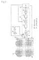
- Fig. 1 illustrates a block diagram of a position detecting device according to a first embodiment of the present invention.
- a position pointer which is a component of a position detection system including the position detection device, includes at least one coil which forms a resonant circuit together with a capacitor.
- a resonance frequency f0 of the resonant circuit is designed so that it is substantially the same as the frequency of a signal communicated between the position pointer and the position detecting device.
- a sensor coil (loop sensor) set 41 includes X-axis direction sensor coils X1 to X40 and Y-axis direction sensor coils Y1 to Y40 arranged in an X-axis direction and a Y-axis direction, respectively.
- the sensor coil set 41 serves as sensor means.
- Each sensor coil serves as a sensor.
- the plurality of sensor coils X1 to X40 and Y1 to Y40 is connected to a selection circuit 42 for selecting each sensor coil.
- An oscillator circuit 43 oscillates at a frequency of f0 which is substantially the same as the resonance frequency of the position pointer.
- the oscillator circuit 43 is connected to a transmission terminal T of a transmission/reception switching circuit 45 via a current driver 44.
- a common terminal of the transmission/reception switching circuit 45 is connected to the selection circuit 42.
- a sensor coil selected by the selection circuit 42 transmits electromagnetic waves of a frequency f0 to the position pointer.
- a reception terminal R of the transmission/reception switching circuit 45 is connected to an amplifier circuit 46, which is connected to a detector circuit 47.
- the detector circuit 47 is connected to a low-pass filter (LPF) 48.
- the low-pass filter 48 is connected to an integration amplifier 49, which holds a reception signal for a predetermined time period.
- the analog voltage held by the integration amplifier 49 is converted to a digital signal by an analog-to-digital (A/D) converter circuit 50.
- the output from the A/D converter circuit 50 is delivered to a central processing unit (CPU) 51.
- CPU central processing unit
- a level detection circuit 52 includes the amplifier circuit 46, the detector circuit 47, the low-pass filter 48, the integration amplifier 49, and the A/D converter circuit 50.
- the CPU 51 also serves as control means.
- the CPU 51 controls the selection circuit 42 to select a predetermined sensor coil from the sensor coil set 41.
- the CPU 51 also controls switching of transmission and reception of the transmission/reception switching circuit 45.
- the CPU 51 controls the level detection circuit 52.
- the selection circuit 42, the oscillator circuit 43, the current driver 44, the transmission/reception switching circuit 45, and the CPU 51 together serve as transmission means for transmitting a position detecting signal used for detecting the position of the position pointer to the position pointer using electromagnetic coupling.
- the selection circuit 42, the transmission/reception switching circuit 45, and the CPU 51 together serve as reception means for receiving a position pointing signal from the position pointer using electromagnetic coupling.
- the level detection circuit 52 and the CPU 51 serve as detection means for detecting a position pointed by the position pointer on the basis of a position pointing signal from the position pointer received by the reception means.
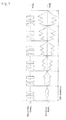
- Fig. 2 is a timing diagram illustrating the operation of the position detecting device according to the first embodiment of the present invention.
- Fig. 3 is a timing diagram illustrating the operation of the position detecting device when selecting and driving each sensor coil according to the first embodiment of the present invention.
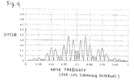
- Fig. 4 illustrates a frequency characteristic of jitter when a signal received by the position detecting device from the position pointer using electromagnetic coupling is influenced by noise generated by an LCD of an electronic apparatus.
- Fig. 4 is a characteristic diagram corresponding to Fig. 8.
- Fig. 5A is a diagram for schematically illustrating the operation of the position detecting device according to the first embodiment of the present invention.
- the operation of the position detecting device is schematically described below with reference to Fig. 5A.
- the position detecting device according to the first embodiment of the present invention includes a plurality of sensor coils a to c, which is grouped into one, and a position pointer 500 including a resonant circuit composed of a coil 501 and a capacitor 502.
- the sensor coils a to c transmit position detecting signals to the position pointer 500 using electromagnetic coupling in a predetermined order.
- the sensor coils a to c, which transmit the position detecting signals also receives position pointing signals from the position pointer 500 (see (1) to (3) shown in Fig. 5A).
- the position detecting device can detect the position pointed by the position pointer 500 on the basis of the received signals.
- the position detecting device When the position detecting device is powered on or when the position detecting device cannot recognize the position pointed by the position pointer 500, the position detecting device operates in a mode in which it scans all of the X-axis direction sensors X1 to X40 and/or Y-axis direction sensors Y1 to Y40 to detect the position pointed by the position pointer 500 (global scanning mode).
- the position detecting device when the position detecting device has already known the position pointed by the position pointer 500, the position detecting device operates in a mode in which it scans only a predetermined number of X-axis direction sensors and Y-axis direction sensors to detect the position pointed by the position pointer 500 (sector scanning mode).
- the selection pattern of the sensor coils in the sector scanning mode is used. However, this description can be applied to the global scanning mode.
- the CPU 51 controls the transmission/reception switching circuit 45 to alternately switch, at a predetermined time interval, between a transmission mode (connection between the common terminal and the transmission terminal T) and a reception mode (connection between the common terminal and the reception terminal R) so as to detect the position pointed by the position pointer 500.
- a signal from the oscillator circuit 43 is transmitted as a position detecting signal from a sensor coil selected by the selection circuit 42 to the position pointer 500 using an alternating magnetic field.
- the resonant circuit of the position pointer 500 receives the position detecting signal using electromagnetic coupling and returns an alternating magnetic field functioning as a position pointing signal.
- the CPU 51 changes the transmission/reception switching circuit 45 to a reception mode so that the sensor coil that transmitted the position detecting signal receives the position pointing signal from the position pointer 500 using electromagnetic coupling.
- the level detection circuit 52 detects the signal level of the received position pointing signal.
- a sensor coil is selected in the order shown in Fig. 2 by the selection circuit 42 under the control of the CPU 51.
- a predetermined number of sensor coils are extracted in the order of arrangement thereof from among the pluralities of sensor coils X1 to X40 and Y1 to Y40 of the sensor coil set 41 into a group (sensor coils 1 to 6 in Fig. 2).
- Each of the sensor coils 1 to 6 is sequentially selected in a predetermined order.
- a detecting signal is delivered to the selected one of the sensor coils 1 to 6, which transmits the detecting signal to the position pointer 500.
- the selected one of the sensor coils 1 to 6 also receives a signal from the position pointer 500 using electromagnetic coupling.
- each of the sensor coils 1 to 6 of the group in the X-axis direction and Y-axis direction is sequentially selected in the predetermined order (selection pattern) that is different from the order of the arrangement thereof in order to transmit a detecting signal to the position pointer 500 and to receive a position pointing signal from the position pointer 500 using electromagnetic coupling.
- a predetermined number of plural groups in which the order of selecting sensor coils are different from each other are sequentially formed.
- the set of the predetermined number of plural groups is repeated as one cycle.
- the plurality of sensor coils in each group is the predetermined number of sensor coils in the vicinity of the position pointed by the position pointer 500. Accordingly, as the position pointer 500 moves, members of sensor coils in each group change. However, in the following descriptions, extracted sensor coils for each group are the same sensor coils 1 to 6 (i.e., the position pointer 500 hardly moves) for simplicity.
- a plurality of selection patterns of the sensor coils 1 to 6 in each group is provided in each of X-axis direction and Y-axis direction (four patterns A to D in this embodiment).
- the plurality of selection patterns A to D forms one cycle.
- the position pointed by the position pointer 500 is detected.
- each of the sensor coils 1 to 6 is scanned three times.
- the CPU 51 computes the position pointed by the position pointer 500 using the sum or average of the signal levels detected three ti mes.
- each of the sensor coils 1 to 6 in the group are arranged in the order of 1, 2, 3, 4, 5, and 6.
- a selection pattern A for a first group each of the sensor coils 1 and 6, which are located at either side of the remaining sensor coils 2 to 5 in the group, is selected in a predetermined order prior to the sensor coils 2 to 5, which are located between the sensor coils 1 and 6.
- the sensor coil 1 is selected first, and subsequently the sensor coil 6 is selected.
- each of the selected sensor coils 1 and 6 transmits a detecting signal to the position pointer 500.
- each of the selected sensor coils 1 and 6, which transmitted the detecting signal in the transmission mode receives a position pointing signal from the position pointer 500 using electromagnetic coupling.
- each of the sensor coils 2 and 5 which are located at either side of the sensor coils between the sensor coils 1 and 6, is selected in a predetermined order. For example, the sensor coil 2 is selected first, and subsequently the sensor coil 5 is selected. Each of the selected sensor coils 2 and 5 carries out a detecting signal transmitting operation and a position pointing signal receiving operation in the same manner as described above.
- each of the sensor coils 3 and 4 which are located between the sensor coils 2 and 5, is selected in a predetermined order. For example, the sensor coil 3 is selected first, and subsequently the sensor coil 4 is selected. Each of the selected sensor coils 3 and 4 carries out a detecting signal transmitting operation and a position pointing signal receiving operation in the same manner as described above.
- the position pointing signal is received by the sensor coil that transmitted a detecting signal.
- the position pointing signal received by the sensor coil is amplified by the amplifier circuit 46 and is detected by the detector circuit 47. High-frequency noise in the position pointing signal detected by the detector circuit 47 is removed by the low-pass filter 48.
- the position pointing signal is then amplified by the integration amplifier 49 and is converted to a digital signal by the A/D converter circuit 50.
- the converted signal is input to the CPU 51.
- the CPU 51 can detect a signal level of the position pointing signal, which is received from the position pointer 500 by the sensor coil that transmitted the detecting signal to the position pointer 500.
- the CPU 51 computes the XY coordinates of a position which exhibits the peak reception signal level using a method such as parabolic approximation and signal levels exhibited by the four sensor coils 2 to 5, which are arranged at middle positions between the sensor coils 1 and 6.
- the sensor coils 1 and 6 located at either side of the sensor coils 2 to 5 are provided for preparatory use only.
- the sensor coils 1 to 6 are used when the four middle sensor coils 2 to 5 cannot detect the position pointed by the position pointer 500 due to, for example, a rapid movement of the position pointer 500.
- the CPU 51 does not use the sensor coils 1 and 6 to compute the position pointed by the position pointer 500.
- the CPU 51 If the CPU 51 cannot detect the position pointed by the position pointer 500 from the signal levels detected by the four middle sensor coils 2 to 5 due to, for example, a rapid movement of the position pointer 500, the CPU 51 computes the peak level of reception signals by using a method such as parabolic approximation and either by using signal levels detected by the outermost sensor coils 1 and 6 and the middlemost sensor coils 3 and 4 or by using, if required, signal levels detected by the outermost sensor coils 1 and 6 and the middle sensor coils 2 and 5. The CPU 51 then computes the coordinates of the position of the peak level as the tentative position pointed by the position pointer.
- a method such as parabolic approximation
- each sensor coil is scanned three times, as shown in Fig. 3.
- the sum or average of the three detected signals is considered to be the detection signal level output from each sensor coil.
- the known position detecting device detects a position pointed by the position pointer 500 by transmitting and receiving a signal four times in a predetermined time period. Accordingly, a residual signal used for the previous detecting operation is accumulated, thus generating a detection error.
- a pause time during which a position pointing signal from the position pointer 500 disappears is provided during an operation selecting one sensor coil from another sensor coil.
- the subsequently selected sensor coil carries out transmission and reception operations of a signal.
- the interval between signal detecting operations of the sensor coils is determined to be more than a predetermined time period so that no residual signal of a signal detection operation of each sensor coil remains. Consequently, the occurrence of a detection error due to a residual signal can be reduced. This operation is also applied to the cases described below.
- each of the selected sensor coils 1 and 6 transmits a detecting signal to the position pointer 500.
- each of the selected sensor coils 1 and 6, which transmitted the detecting signal in the transmission mode receives a position pointing signal from the position pointer 500 using electromagnetic coupling.
- the sensor coils 2 and 5 which are located at either side of the sensor coils 3 to 4, are selected in an order different from that defined in the selection pattern A. That is, the sensor coil 5 is selected first, and subsequently the sensor coil 2 is selected.
- Each of the selected sensor coils 2 and 5 carries out a detecting signal transmitting operation and a position pointing signal receiving operation in the same manner as described above.
- the sensor coils 3 and 4 which are located between 2 and 5, are selected in the same order as that defined in the selection pattern A. That is, the sensor coil 3 is selected first, and subsequently the sensor coil 4 is selected.
- Each of the selected sensor coils 3 and 4 carries out a detecting signal transmitting operation and a position pointing signal receiving operation in the same manner as described above.
- each of the selected sensor coils 1 and 6 transmits a detecting signal to the position pointer 500.
- each of the selected sensor coils 1 and 6, which transmitted the detecting signal in the transmission mode receives a position pointing signal from the position pointer 500 using electromagnetic coupling.
- the sensor coils 2 and 5 which are located at either side of the sensor coils 3 to 4, are selected in an order different from that defined in the selection pattern A. That is, the sensor coil 2 is selected first, and subsequently the sensor coil 5 is selected. Each of the selected sensor coils 2 and 5 carries out a detecting signal transmitting operation and a position pointing signal receiving operation in the same manner as described above.
- the sensor coils 3 and 4 which are arranged between 2 and 5, are selected in an order different from that defined in the selection pattern A. That is, the sensor coil 4 is selected first, and subsequently the sensor coil 3 is selected.
- Each of the selected sensor coils 3 and 4 carries out a detecting signal transmitting operation and a position pointing signal receiving operation in the same manner as described above.
- a selection pattern D for a fourth group like the selection pattern A, the sensor coils 1 and 6, which are located at either side of the remaining sensor coils 2 to 5 in the group, are selected in a predetermined order prior to the sensor coils 2 to 5, which are located between the sensor coils 1 and 6.
- each of the selected sensor coils 1 and 6 transmits a detecting signal to the position pointer 500.
- each of the selected sensor coils 1 and 6, which transmitted the detecting signal in the transmission mode receives a position pointing signal from the position pointer 500 using electromagnetic coupling.
- the sensor coils 2 and 5 which are located at either side of the sensor coils 3 to 4, are selected in an order different from that defined in the selection pattern A. That is, the sensor coil 5 is selected first, and subsequently the sensor coil 2 is selected.
- Each of the selected sensor coils 2 and 5 carries out a detecting signal transmitting operation and a position pointing signal receiving operation in the same manner as described above.
- each of the sensor coils 3 and 4 which are located between 2 and 5, is selected in an order different from that defined in the selection pattern A. That is, the sensor coil 4 is selected first, and subsequently the sensor coil 3 is selected.
- Each of the selected sensor coils 3 and 4 carries out a detecting signal transmitting operation and a position pointing signal receiving operation in the same manner as described above.
- the above-described operations are alternately carried out for the X-axis sensor coils and for the Y-axis sensor coils.
- the above-described plural selection patterns A to D form one cycle. By repeating the cycle, a tentative position pointed by the position pointer 500 is detected from each of the selection patterns.
- the CPU 51 computes a final position pointed by the position pointer 500 by obtaining a moving average of a predetermined number (e.g., eight) of the tentative positions detected from the selection patterns. Consequently, the occurrence of a detection error due to high-frequency noise caused by the body of an electronic apparatus can be reduced, and therefore, more precise detection of the coordinates can be provided.
- a predetermined number e.g. eight
- a large low-frequency jitter is reduced for noise at positions of a frequency distant from a sensor-coil scanning frequency f0 by ⁇ 0.5 frequencies, that is, at positions of f0 ⁇ 0.5/Ts, compared with the frequency characteristic shown in Fig. 8.
- the reduction of influence of the noise reduces the occurrence of a detection error of the position pointed by the position pointer 500.
- the known position detecting device sequentially selects and drives each of the sensor coils 1 to 6. Since the detection signal level of each sensor coil significantly rises or falls as time elapses, there is a possibility of the detection signal level not reaching the proper signal level in a short time. However, as shown in Fig. 2, by selecting each sensor coil as in the present embodiment, the difference between the detection signal levels of the sensor coils can be reduced. Accordingly, the detection signal level reaches the proper signal level in a short time. As a result, the occurrence of a detection error can be reduced, and therefore, precise position detection can be provided.
- a position detecting device includes a plurality of sensor coils X1 to X40 and Y1 to Y40 arranged in a predetermined order to receive signals from a position pointer; reception means (the selection circuit 42, the transmission/reception switching circuit 45, and the CPU 51) for extracting a predetermined number of the plurality of sensor coils 1 to 6 from among the pluralities of sensor coils X1 to X40 and Y1 to Y40 in an order of the arrangement to form a group and for receiving a signal using electromagnetic coupling from the position pointer with each of the sensor coils 1 to 6 in the group selected in a predetermined order; and detection means (the CPU 51 and the level detection circuit 52) for detecting a position pointed by the position pointer on the basis of position pointing signals received from the selected sensor coils.
- the reception means sequentially forms a plurality of groups in which the selection order of the extracted sensor coils 1 to 6 is different from each other.
- the position pointing signal is received by a sensor coil selected in a predetermined order for each group using electromagnetic coupling.
- the detection means detects the position pointed by the position pointer on the basis of position pointing signals received from the selected sensor coils.
- the sensor coils extracted from among the plurality of sensor coils X1 to X40 and Y1 to Y40 are a predetermined number of the plurality of sensor coils arranged in the vicinity of a position pointed by the position pointer 500.
- the sensor coils extracted from among the plurality of sensor coils X1 to X40 and Y1 to Y40 are all of the sensor coils in one of directions of the axes or in directions of the both axes.
- the reception means receives a signal from the position pointer using electromagnetic coupling by selecting sensor coils located at either side of the middle sensors in each group prior to selecting each of the middle sensors. That is, the reception means selects the sensor coils 1 and 6, which are located at either side of the other sensor coils in the group, prior to the sensor coils 2 to 5, which are located between the sensor coils 1 and 6. If the preparatory sensor coils 1 and 6 are not used, the sensor coils 2 and 5 correspond to sensor coils located at either side of the other sensor coils in the group. Thus, the reception means selects the sensor coils 2 and 5 prior to the sensor coils 3 to 4, which are located between the sensor coils 2 and 5.
- the reception means selects each of the sensor coils between the sensor coils 1 to 6 of the group while changing an order of selecting a sensor coil in a predetermined manner for each group so that the order of selecting a sensor coil is different for each group.
- the selected sensor coil then receives a signal from the position pointer using electromagnetic coupling.
- the reception means also determines the set of the plurality of groups to be one cycle and repeats the reception according to the cycle.
- the reception means includes transmission means for delivering a position detecting signal for detecting a position pointed by the position pointer to the sensor coil in order to transmit the position detecting signal from the sensor coil to the position pointer using electromagnetic coupling.
- the transmission means selects the same sensor coil as that selected by the reception means and delivers the position detecting signal to that sensor coil.
- the position detecting device includes transmission means for delivering a position detecting signal for detecting a position pointed by the position pointer to the sensor coil in order to transmit the position detecting signal from the sensor coil to the position pointer using electromagnetic coupling or electrostatic coupling.
- the transmission means selects the sensor coil closest to the position pointer in each group and delivers the position detecting signal to that sensor coil.
- the detection means detects tentative positions pointed by the position pointer on the basis of signals received by the sensor coils in each group and determines the moving average of a predetermined number of the tentative positions pointed by the position pointer to be the position pointed by the position pointer. Consequently, when the unit frequency of a sensor-coil scanning frequency is a reciprocal number 1/Ts of scanning time Ts for scanning two coils (one coil depending on a computing method of the coordinates of the position pointer), a high-frequency jitter is reduced for noise distributed at positions excluding positions of a frequency distant from a sensor-coil scanning frequency f0 by ⁇ 0.5 frequencies, that is, at positions excluding positions of f0 ⁇ 0.5/Ts. Since the influence of the high-frequency jitter is reduced, highly precise detection of the position can be provided.
- the present embodiment has been described with reference to a position detecting device using an electromagnetic coupling method in which transmission and reception of a signal between a position pointer and a position detecting device is carried out via electromagnetic coupling
- the present embodiment can be applied to a position detecting device using an electrostatic coupling method in which transmission and reception of a signal between a position pointer and a position detecting device is carried out via electrostatic coupling, since the present embodiment is effective for reducing periodic electrostatic noise (e.g., noise caused by a liquid crystal display device or a backlight).
- the following embodiments can be applied to a position detecting device using an electrostatic coupling method as well as a position detecting device using an electromagnetic coupling method.
- FIG. 5B is a diagram schematically illustrating the operation of the position detecting device according to the second embodiment.
- identical elements to those illustrated and described in relation to Fig. 5A are designated by identical reference numerals.
- a block diagram and timing diagrams of the second embodiment are identical to the block diagram of the first embodiment shown in Fig. 1 and the timing diagrams of the first embodiment shown in Figs. 2 and 3. Only the driving method of a plurality of sensor coils a to c in a group is different. In the first embodiment, the sensor coils in a group is sequentially selected and driven in a predetermined order, and a sensor coil that transmitted a position detecting signal receives a position pointing signal from the position pointer 500.
- the second embodiment differs from the first embodiment in that a sensor coil b located at the position closest to the position pointer 500 transmits a position pointing signal to the position pointer 500 using electromagnetic coupling, and the position detecting device sequentially selects and drives each sensor coil in a group in a predetermined order and at a predetermined timing (in an order and at a timing shown in Figs. 2 and 3) to receive a position pointing signal from the position pointer 500 using electromagnetic coupling.
- the sensor coil b located at a position closest to the position pointer 500 in each group is selected.
- the position detecting signal is transmitted to the position pointer 500 using electromagnetic coupling.
- a position pointing signal is received by the selected sensor coil (see (1) through (3) in Fig. 5B).
- position pointing signals are sequentially received by the selected and driven sensor coils in the same order as that in the first embodiment. Subsequently, the position of the position pointer 500 can be detected in the same manner as in the first embodiment.
- the second embodiment can provide the characteristic identical to that shown in Fig. 4. Consequently, the influence of noise that causes low-frequency jitter can be reduced, and therefore, highly precise detection of the position can be provided.
- a position detecting device according to a third embodiment of the present invention is described next.
- Fig. 5C is a diagram schematically illustrating the operation of the position detecting device according to the third embodiment.
- identical elements to those illustrated and described in relation to Figs. 5A and 5B are designated by identical reference numerals.
- a block diagram and timing diagrams of the third embodiment are identical to the block diagram of the first embodiment shown in Fig. 1 and the timing diagrams of the first embodiment shown in Figs. 2 and 3. Only the driving method of a plurality of sensor coils a to c in a group and the reception method are different.
- the sensor coils in a group is sequentially selected and driven in a predetermined order, and a sensor coil that transmitted a position detecting signal receives a position pointing signal from the position pointer 500.
- the third embodiment differs from the first embodiment in that each of the plurality of sensor coils a to c is sequentially selected and driven (in the order and at timing shown in Figs.
- the selected sensor coils sequentially transmit a position detecting signal to the position pointer 500 using electromagnetic coupling by delivering the position detecting signals to the selected sensor coils, and a sensor coil b located at a position closest to the position pointer 500 receives, from the position pointer 500, a position pointing signal in response to the position detecting signal transmitted from each sensor coil using electromagnetic coupling.
- the sensor coils a to c in each group are sequentially selected and driven in the same order as that shown in Fig. 2.
- the selected sensor coil transmits a position detecting signal to the position pointer 500 using electromagnetic coupling.
- the sensor coil b located at a position closest to the position pointer 500 receives position pointing signals corresponding to the position detecting signals transmitted from the sensor coils a to c using electromagnetic coupling (see (1) through (3) in Fig. 5C).
- each sensor coil (each sensor coil in the sensor coil set 41 shown in Fig. 1) functions as a transmission unit for transmitting a position detecting signal. Also, each sensor coil (each sensor coil in the sensor coil set 41 shown in Fig. 1) functions as a reception unit for receiving a position pointing signal.
- a position detecting device includes a plurality of transmission units arranged in a predetermined order for transmitting position detecting signals to a position pointer using electromagnetic coupling or electrostatic coupling; transmission means for extracting a predetermined number of the plurality of transmission units from among the plurality of transmission units in an order of the arrangement to form a group and for delivering a position detecting signal to a transmission unit selected from among the transmission units in the group in a predetermined order so as to transmit the position detecting signal to the position pointer; reception means for receiving a position pointing signal from the position pointer using electromagnetic coupling or electrostatic coupling; and detection means for detecting a position pointed by the position pointer on the basis of the position pointing signal received from the reception means.
- the transmission means sequentially forms a plurality of groups in which the order of selecting the extracted transmission units is different from each other and transmits the position detecting signal to a transmission unit selected in the selection order for each group.
- the transmission means selects transmission units located at either side of the middle transmission units in each group prior to selecting each of the middle transmission units and delivers position detecting signals. Also, the transmission means selects each of the middle transmission units while changing an order of selecting a transmission unit in a predetermined manner for each group so that the order of selecting a transmission unit is different for each group. The transmission means then delivers the position detecting signal to the selected transmission unit. The transmission means also determines the set of the plurality of groups to be one cycle and repeats the transmission according to the cycle.
- the detection means detects tentative positions pointed by the position pointer on the basis of signals from the position pointer in response to the position detecting signals transmitted from a transmission unit in each group. The detection means then determines the moving average of a predetermined number of the tentative positions pointed by the position pointer to be the position pointed by the position pointer. Additionally, the reception means selects a transmission unit located at a position closest to the position pointer in each group and receives position pointing signals from the position pointer using that transmission unit.
- the third embodiment can also provide the characteristic identical to that shown in Fig. 4.
- the influence of noise that causes low-frequency jitter can be reduced, and therefore, highly precise detection of the position can be provided.
- a position detecting device may include a coil or a sensor dedicated for transmission and a plurality of sensor coils dedicated for reception and arranged in an XY matrix.
- the position detecting device causes the coil dedicated for transmission to transmit a position detecting signal to a position pointer, and selects and drives the sensor coils dedicated for reception in the above-described manner to detect a position pointed by the position pointer on the basis of signals received by the sensor coils.
- the axis of sensors for transmission may be different from the axis of sensors for reception.
- X-axis sensor coils may carry out transmission whereas Y-axis sensor coils may carry out reception.
- Y-axis sensor coils may carry out transmission whereas X-axis sensor coils may carry out reception.
- the present invention can be applied to a position detecting device in which a plurality of transmission coils for transmitting a signal is arranged in a matrix, the transmission coils sequentially transmit a signal to a position pointer having a coil using electromagnetic coupling, the position pointer detects the signal from the coil using electromagnetic coupling, and a position pointed by the position pointer is detected on the basis of the signal detected by the position pointer.
- tentative pointed positions are computed for selection patterns of the groups and a proper position pointed by the position pointer is computed by obtaining the moving average of a predetermined number of the tentative pointed positions.
- the tentative pointed positions in the groups may be determined to be proper positions pointed by the position pointer without computing the moving average.
- the present embodiment has been described with reference to four groups including a plurality of selected sensors and one cycle formed by the four groups, the number of groups is not intended to be limited to four. Also, the groups do not necessarily form a cycle.
- a position detecting device includes a position pointer, a plurality of sensors arranged in a direction of detecting a position, reception means for receiving a signal including positional information about the position pointer using the sensors via electromagnetic coupling or electrostatic coupling, and detection means for detecting a position pointed by the position pointer from the received signal.
- the reception means extracts a predetermined number of sensors from among the plurality of sensors to form each of a plurality of groups and defines a unique order of selecting a sensor to be scanned for each group. The order of selecting the sensors in a group to be scanned is different from that in the immediately previously scanned group.
- a position detecting device includes a plurality of sensors arranged in a predetermined order for receiving a signal from a position pointer; reception means for extracting a predetermined number of the plurality of sensors from among the plurality of sensors in an order of the arrangement to form each of a plurality of groups and receiving the signal from the position pointer using the sensors selected in a predetermined order from among the sensors in the group via electromagnetic coupling or electrostatic coupling; and detection means for detecting a position pointed by the position pointer on the basis of the signals received by the selected sensors.
- the reception means sequentially forms a plurality of groups in which an order of selecting the extracted sensors is different from each other, and receives the signal from the position pointer for each group using the sensors selected according to the order defined for each group via electromagnetic coupling or electrostatic coupling.
- the detection means detects a position pointed by the position pointer on the basis of the signals received by the selected sensors.
- a position detecting device includes a position pointer; a plurality of transmission units arranged in a direction of detecting a position; transmission means for transmitting a signal including positional information about the position pointer using the sensors via electromagnetic coupling or electrostatic coupling; reception means for receiving a signal in response to the transmission; and detection means for detecting a position pointed by the position pointer from the received signal.
- the transmission means extracts a predetermined number of transmission units from among the plurality of transmission units in an order of the arrangement thereof to form each of a plurality of groups and defines a unique order of selecting a transmission unit to be scanned for each group. The order of selecting the transmission units in a group to be scanned is different from that in the immediately previously scanned group.
- a position detecting device includes a plurality of transmission units arranged in a predetermined order for transmitting a position detecting signal to a position pointer using electromagnetic coupling or electrostatic coupling; transmission means for extracting a predetermined number of plural transmission units in the order of the arrangement thereof from among the plurality of transmission units to form each of a plurality of groups and delivering a position detecting signal to the transmission unit selected in a predetermined order from among the transmission units in each group in order to transmit the position detecting signal to the position pointer; reception means for receiving a position pointing signal from the position pointer using electromagnetic coupling or electrostatic coupling; and detection means for detecting a position pointed by the position pointer on the basis of the signal received by the reception means.
- the transmission means sequentially forms a plurality of groups in which an order of selecting the extracted transmission units is different from each other, and delivers the position detecting signal to the transmission unit in each group selected according to the order defined for each group. Accordingly, a position detecting device having a superior noise characteristic can be provided.
- a position detecting device includes a position pointer, a plurality of sensors arranged in a direction of detecting a position, reception means for receiving a position pointed by the position pointer using the sensors via electromagnetic coupling or electrostatic coupling, and detection means for detecting the position pointed by the position pointer from the received signal.
- the reception means defines a unique scanning scheme in which sensors are selected in a predetermined order from among the plurality of sensors. The order of selecting the sensors in a scanning scheme is different from that in the immediately previously used scanning scheme. Thus, the noise characteristic can be improved.
- the present invention can be applied to a position detecting device that detects at least a position of a position pointer and the position pointer used by the position detecting device.
- the present invention can be applied to a position detecting device and a position pointer used by the position detecting device using electromagnetic coupling or electrostatic coupling, which are used as an input unit of a computer aided design (CAD) terminal, a computer, a cell phone, a personal handyphone system (PHS), or a personal digital assistant (PDA).
- CAD computer aided design
- PDA personal digital assistant
- the present invention can be applied to a position detecting device that detects not only the position of a position pointer but also the posture of the position pointer.
Landscapes
- Engineering & Computer Science (AREA)
- Physics & Mathematics (AREA)
- General Engineering & Computer Science (AREA)
- Theoretical Computer Science (AREA)
- Electromagnetism (AREA)
- Human Computer Interaction (AREA)
- General Physics & Mathematics (AREA)
- Measurement Of Length, Angles, Or The Like Using Electric Or Magnetic Means (AREA)
- Position Input By Displaying (AREA)
Applications Claiming Priority (1)
| Application Number | Priority Date | Filing Date | Title |
|---|---|---|---|
| JP2004297159A JP4330513B2 (ja) | 2004-10-12 | 2004-10-12 | 位置検出装置 |
Publications (3)
| Publication Number | Publication Date |
|---|---|
| EP1647879A2 true EP1647879A2 (fr) | 2006-04-19 |
| EP1647879A3 EP1647879A3 (fr) | 2007-10-10 |
| EP1647879B1 EP1647879B1 (fr) | 2017-01-11 |
Family
ID=35482149
Family Applications (1)
| Application Number | Title | Priority Date | Filing Date |
|---|---|---|---|
| EP05109321.9A Expired - Lifetime EP1647879B1 (fr) | 2004-10-12 | 2005-10-07 | Dispositif de détection de position |
Country Status (3)
| Country | Link |
|---|---|
| US (1) | US7656390B2 (fr) |
| EP (1) | EP1647879B1 (fr) |
| JP (1) | JP4330513B2 (fr) |
Cited By (3)
| Publication number | Priority date | Publication date | Assignee | Title |
|---|---|---|---|---|
| CN103164089A (zh) * | 2011-12-16 | 2013-06-19 | 元太科技工业股份有限公司 | 触控面板 |
| CN112260661A (zh) * | 2020-10-21 | 2021-01-22 | 深圳市绘王动漫科技有限公司 | 信号处理电路及位置检测装置 |
| EP4293487A3 (fr) * | 2022-06-15 | 2024-02-28 | Samsung Display Co., Ltd. | Dispositif d'affichage et système de détection tactile le comprenant |
Families Citing this family (11)
| Publication number | Priority date | Publication date | Assignee | Title |
|---|---|---|---|---|
| US20080275669A1 (en) * | 2007-04-13 | 2008-11-06 | Tomohiro Ihashi | Pedometer |
| US9294157B2 (en) * | 2007-08-20 | 2016-03-22 | Gui-Yang Lu | Radio-frequency identification system |
| US8426799B2 (en) * | 2008-08-07 | 2013-04-23 | Rapt Ip Limited | Optical control system with feedback control |
| CN101807135B (zh) * | 2009-02-16 | 2011-12-07 | 太瀚科技股份有限公司 | 无边缘区域的数字板及其坐标计算电路 |
| JP5430339B2 (ja) | 2009-10-19 | 2014-02-26 | 株式会社ワコム | 位置検出装置及び位置指示器 |
| JP5484097B2 (ja) * | 2010-01-27 | 2014-05-07 | 株式会社ワコム | 位置検出装置および方法 |
| US9310911B2 (en) * | 2011-07-29 | 2016-04-12 | Sharp Kabushiki Kaisha | Display device |
| US9632629B2 (en) | 2011-09-29 | 2017-04-25 | Parade Technologies, Ltd. | Sensor patterns with reduced noise coupling |
| KR102007690B1 (ko) * | 2012-10-10 | 2019-10-21 | 삼성전자주식회사 | 펜의 위치를 측정하는 위치 측정 장치 및 그 제어 방법 |
| EP3299936B1 (fr) | 2015-05-21 | 2020-01-01 | Wacom Co., Ltd. | Stylet actif |
| US11536589B2 (en) | 2021-03-09 | 2022-12-27 | Toyota Motor Engineering & Manufacturing North America, Inc. | Electromagnetic noise position sensing |
Citations (1)
| Publication number | Priority date | Publication date | Assignee | Title |
|---|---|---|---|---|
| EP0740265A2 (fr) | 1995-04-27 | 1996-10-30 | Wacom Co., Ltd. | Méthode de détection de position pour utilisation dans un appareil d'entrée de coordonnées |
Family Cites Families (6)
| Publication number | Priority date | Publication date | Assignee | Title |
|---|---|---|---|---|
| JP2971488B2 (ja) | 1989-11-01 | 1999-11-08 | 株式会社ワコム | 位置検出装置 |
| JPH0675683A (ja) | 1992-08-27 | 1994-03-18 | Wacom Co Ltd | 位置検出装置 |
| JP3001394B2 (ja) * | 1995-03-10 | 2000-01-24 | 株式会社ワコム | センサコイル・パターン及び座標入力装置 |
| JP3015275B2 (ja) * | 1995-04-10 | 2000-03-06 | 株式会社ワコム | 位置検出装置およびそれに用いる位置指示器 |
| JP4540088B2 (ja) | 2001-08-24 | 2010-09-08 | 株式会社ワコム | 位置検出装置 |
| JP3910814B2 (ja) | 2001-09-05 | 2007-04-25 | 株式会社ワコム | 位置検出装置及びその位置指示器 |
-
2004
- 2004-10-12 JP JP2004297159A patent/JP4330513B2/ja not_active Expired - Fee Related
-
2005
- 2005-10-07 EP EP05109321.9A patent/EP1647879B1/fr not_active Expired - Lifetime
- 2005-10-11 US US11/246,959 patent/US7656390B2/en active Active
Patent Citations (1)
| Publication number | Priority date | Publication date | Assignee | Title |
|---|---|---|---|---|
| EP0740265A2 (fr) | 1995-04-27 | 1996-10-30 | Wacom Co., Ltd. | Méthode de détection de position pour utilisation dans un appareil d'entrée de coordonnées |
Cited By (7)
| Publication number | Priority date | Publication date | Assignee | Title |
|---|---|---|---|---|
| CN103164089A (zh) * | 2011-12-16 | 2013-06-19 | 元太科技工业股份有限公司 | 触控面板 |
| CN103164089B (zh) * | 2011-12-16 | 2016-08-03 | 元太科技工业股份有限公司 | 触控面板 |
| CN112260661A (zh) * | 2020-10-21 | 2021-01-22 | 深圳市绘王动漫科技有限公司 | 信号处理电路及位置检测装置 |
| JP2022068100A (ja) * | 2020-10-21 | 2022-05-09 | 深▲セン▼市絵王動漫科技有限公司 | 信号処理回路および位置検出装置 |
| EP4009150A1 (fr) * | 2020-10-21 | 2022-06-08 | Shenzhen Huion Animation Technology Co., Ltd. | Circuit de traitement de signal et dispositif de détection de position l'utilisant |
| EP4293487A3 (fr) * | 2022-06-15 | 2024-02-28 | Samsung Display Co., Ltd. | Dispositif d'affichage et système de détection tactile le comprenant |
| US12216860B2 (en) | 2022-06-15 | 2025-02-04 | Samsung Display Co., Ltd | Display device and a touch sensing system including the same |
Also Published As
| Publication number | Publication date |
|---|---|
| JP4330513B2 (ja) | 2009-09-16 |
| EP1647879A3 (fr) | 2007-10-10 |
| JP2006113628A (ja) | 2006-04-27 |
| US20060087422A1 (en) | 2006-04-27 |
| US7656390B2 (en) | 2010-02-02 |
| EP1647879B1 (fr) | 2017-01-11 |
Similar Documents
| Publication | Publication Date | Title |
|---|---|---|
| EP1647879A2 (fr) | Dispositif de détection de position | |
| US5691513A (en) | Scanning method for sensor coils in coordinate data input device | |
| EP1288849B1 (fr) | Détecteur de position | |
| CN108021279B (zh) | 触控处理装置、方法与电子系统 | |
| JPH07311647A (ja) | 位置検出装置及びそのノイズ除去方法 | |
| JPS6370326A (ja) | 位置検出装置 | |
| EP2690533A2 (fr) | Dispositif de détection de position d'indicateur | |
| KR102151552B1 (ko) | 전자기 유도 방식의 위치 검출 센서 | |
| JP3517449B2 (ja) | 位置検出方法及びその装置 | |
| US10345983B2 (en) | Detection apparatus, inputting apparatus, and detection method in which switch circuit is controlled to cause first and second signals to be supplied to first and second sensor electrodes, respectively | |
| US12366947B2 (en) | Method executed by sensor controller of electromagnetic resonance system, sensor controller, and position detection device | |
| JPS63108424A (ja) | 位置検出装置 | |
| US7675507B2 (en) | Position detecting system and position detecting apparatus | |
| EP1291811B1 (fr) | Détecteur de position et indicateur de position associé | |
| US20110267292A1 (en) | Method for simultaneously operating multiple pointers on electromagnetic position detection apparatus | |
| JP4564680B2 (ja) | 位置検出装置 | |
| JP4117751B2 (ja) | デジタイザ及び位置指示器情報検出方法 | |
| JP2021086538A (ja) | タッチパネル装置およびタッチパネル装置の制御方法 | |
| KR101990010B1 (ko) | 전자기 유도 입력 방식의 센싱 장치 및 그 제어 방법 | |
| JPH0675034U (ja) | コードレスデジタイザ | |
| KR20250020413A (ko) | 위치 검출 장치, 전자 유도 펜, 및 위치 검출 시스템 | |
| JP3540049B2 (ja) | 位置検出装置及びその位置指示器 | |
| JPS63280321A (ja) | 位置検出装置 |
Legal Events
| Date | Code | Title | Description |
|---|---|---|---|
| PUAI | Public reference made under article 153(3) epc to a published international application that has entered the european phase |
Free format text: ORIGINAL CODE: 0009012 |
|
| AK | Designated contracting states |
Kind code of ref document: A2 Designated state(s): AT BE BG CH CY CZ DE DK EE ES FI FR GB GR HU IE IS IT LI LT LU LV MC NL PL PT RO SE SI SK TR |
|
| AX | Request for extension of the european patent |
Extension state: AL BA HR MK YU |
|
| PUAL | Search report despatched |
Free format text: ORIGINAL CODE: 0009013 |
|
| AK | Designated contracting states |
Kind code of ref document: A3 Designated state(s): AT BE BG CH CY CZ DE DK EE ES FI FR GB GR HU IE IS IT LI LT LU LV MC NL PL PT RO SE SI SK TR |
|
| AX | Request for extension of the european patent |
Extension state: AL BA HR MK YU |
|
| 17P | Request for examination filed |
Effective date: 20080410 |
|
| AKX | Designation fees paid |
Designated state(s): DE FR GB |
|
| 17Q | First examination report despatched |
Effective date: 20120223 |
|
| GRAP | Despatch of communication of intention to grant a patent |
Free format text: ORIGINAL CODE: EPIDOSNIGR1 |
|
| INTG | Intention to grant announced |
Effective date: 20160818 |
|
| GRAS | Grant fee paid |
Free format text: ORIGINAL CODE: EPIDOSNIGR3 |
|
| GRAA | (expected) grant |
Free format text: ORIGINAL CODE: 0009210 |
|
| AK | Designated contracting states |
Kind code of ref document: B1 Designated state(s): DE FR GB |
|
| REG | Reference to a national code |
Ref country code: GB Ref legal event code: FG4D |
|
| REG | Reference to a national code |
Ref country code: DE Ref legal event code: R096 Ref document number: 602005051122 Country of ref document: DE |
|
| REG | Reference to a national code |
Ref country code: DE Ref legal event code: R097 Ref document number: 602005051122 Country of ref document: DE |
|
| PLBE | No opposition filed within time limit |
Free format text: ORIGINAL CODE: 0009261 |
|
| STAA | Information on the status of an ep patent application or granted ep patent |
Free format text: STATUS: NO OPPOSITION FILED WITHIN TIME LIMIT |
|
| 26N | No opposition filed |
Effective date: 20171012 |
|
| REG | Reference to a national code |
Ref country code: FR Ref legal event code: ST Effective date: 20180629 |
|
| PG25 | Lapsed in a contracting state [announced via postgrant information from national office to epo] |
Ref country code: FR Free format text: LAPSE BECAUSE OF NON-PAYMENT OF DUE FEES Effective date: 20171031 |
|
| PGFP | Annual fee paid to national office [announced via postgrant information from national office to epo] |
Ref country code: GB Payment date: 20201022 Year of fee payment: 16 Ref country code: DE Payment date: 20201022 Year of fee payment: 16 |
|
| REG | Reference to a national code |
Ref country code: DE Ref legal event code: R119 Ref document number: 602005051122 Country of ref document: DE |
|
| GBPC | Gb: european patent ceased through non-payment of renewal fee |
Effective date: 20211007 |
|
| PG25 | Lapsed in a contracting state [announced via postgrant information from national office to epo] |
Ref country code: GB Free format text: LAPSE BECAUSE OF NON-PAYMENT OF DUE FEES Effective date: 20211007 Ref country code: DE Free format text: LAPSE BECAUSE OF NON-PAYMENT OF DUE FEES Effective date: 20220503 |