EP1647890A2 - Bereiche für die Sicherheitsübertragung von Knoten in einem Clustersystem - Google Patents
Bereiche für die Sicherheitsübertragung von Knoten in einem Clustersystem Download PDFInfo
- Publication number
- EP1647890A2 EP1647890A2 EP05108801A EP05108801A EP1647890A2 EP 1647890 A2 EP1647890 A2 EP 1647890A2 EP 05108801 A EP05108801 A EP 05108801A EP 05108801 A EP05108801 A EP 05108801A EP 1647890 A2 EP1647890 A2 EP 1647890A2
- Authority
- EP
- European Patent Office
- Prior art keywords
- failover
- node
- scope
- resource group
- nodes
- Prior art date
- Legal status (The legal status is an assumption and is not a legal conclusion. Google has not performed a legal analysis and makes no representation as to the accuracy of the status listed.)
- Granted
Links
Images




Classifications
-
- G—PHYSICS
- G06—COMPUTING OR CALCULATING; COUNTING
- G06F—ELECTRIC DIGITAL DATA PROCESSING
- G06F11/00—Error detection; Error correction; Monitoring
- G06F11/07—Responding to the occurrence of a fault, e.g. fault tolerance
- G06F11/16—Error detection or correction of the data by redundancy in hardware
- G06F11/20—Error detection or correction of the data by redundancy in hardware using active fault-masking, e.g. by switching out faulty elements or by switching in spare elements
- G06F11/202—Error detection or correction of the data by redundancy in hardware using active fault-masking, e.g. by switching out faulty elements or by switching in spare elements where processing functionality is redundant
- G06F11/2023—Failover techniques
-
- G—PHYSICS
- G06—COMPUTING OR CALCULATING; COUNTING
- G06F—ELECTRIC DIGITAL DATA PROCESSING
- G06F11/00—Error detection; Error correction; Monitoring
-
- G—PHYSICS
- G06—COMPUTING OR CALCULATING; COUNTING
- G06F—ELECTRIC DIGITAL DATA PROCESSING
- G06F11/00—Error detection; Error correction; Monitoring
- G06F11/07—Responding to the occurrence of a fault, e.g. fault tolerance
- G06F11/16—Error detection or correction of the data by redundancy in hardware
- G06F11/20—Error detection or correction of the data by redundancy in hardware using active fault-masking, e.g. by switching out faulty elements or by switching in spare elements
- G06F11/202—Error detection or correction of the data by redundancy in hardware using active fault-masking, e.g. by switching out faulty elements or by switching in spare elements where processing functionality is redundant
- G06F11/2023—Failover techniques
- G06F11/2028—Failover techniques eliminating a faulty processor or activating a spare
-
- G—PHYSICS
- G06—COMPUTING OR CALCULATING; COUNTING
- G06F—ELECTRIC DIGITAL DATA PROCESSING
- G06F11/00—Error detection; Error correction; Monitoring
- G06F11/07—Responding to the occurrence of a fault, e.g. fault tolerance
- G06F11/16—Error detection or correction of the data by redundancy in hardware
- G06F11/20—Error detection or correction of the data by redundancy in hardware using active fault-masking, e.g. by switching out faulty elements or by switching in spare elements
- G06F11/202—Error detection or correction of the data by redundancy in hardware using active fault-masking, e.g. by switching out faulty elements or by switching in spare elements where processing functionality is redundant
- G06F11/2035—Error detection or correction of the data by redundancy in hardware using active fault-masking, e.g. by switching out faulty elements or by switching in spare elements where processing functionality is redundant without idle spare hardware
Definitions
- the invention relates generally to clustered computing nodes, and more particularly to handling failures of applications or the hosting nodes of a cluster.
- a cluster is a set of interconnected computer system servers arranged as nodes that provide access to resources such as server application programs.
- resources such as server application programs.
- One reason to have a server cluster is that multiple linked computer systems significantly improve computing availability and reliability, as well as having more processing power, speed and other resources by way of distributing the load.
- failures include a computer system crash, a break in a communications link between nodes, intentional shutdowns for maintenance or the like, inadvertent shutdowns such as accidentally unplugging power or a communications cable, and so on.
- resource group which is a collection of one or more resources such as application programs and related resources such as network names, IP addresses and the like that is managed as a single unit with respect to failover
- resource group which is a collection of one or more resources such as application programs and related resources such as network names, IP addresses and the like that is managed as a single unit with respect to failover
- this tended to overwhelm certain nodes because many resource groups had the same default configuration for their preferred nodes.
- present clustering technology provides that when more than one surviving node is available, an algorithm based on random numbers is used to choose the destination node for resource groups if no configuration is provided for the preferred owners list for a resource group (at least among nodes that are capable of hosting the groups), so that no one node is overwhelmed by taking on too many resource groups of the failed node or nodes.
- cluster nodes are physically close, as enterprises (particularly large enterprises) often separate two or more subsets of such closely-interconnected clustered nodes from one another by relatively large geographic distances.
- a purpose of this is disaster protection, so as to still have some number of nodes operating in the event of a hurricane, fire, earthquake or the like that can cause an entire physically close subset of interconnected nodes to fail as a whole, whether the reason for the failure is the actual failure of the nodes, or a break in the transmission medium between that subset of nodes and other distant nodes.
- a problem with disaster protection by geographic separation is that the communications bandwidth between one subset of closely-interconnected nodes with that of another subset is far lower than the communications bandwidth within the subset.
- some cluster administrators do not necessarily want resource groups to automatically failover from one closely-interconnected subset to another (unless an entire subset fails), because the time and expense of failing over resources from even one node is significant, given the low-bandwidth connection. Instead, cluster administrators often would prefer to have the resource groups failover only to closely interconnected nodes.
- the present invention is directed towards a system and method by which a failover scopes are defined, each comprising a subset of identified nodes of a cluster, and by which resource groups may be associated with an ordered list of one or more failover scopes.
- a failover scope When a failover occurs, each resource group automatically fails over to a surviving node that is listed within its failover scope. Based on the ordering, until successful, failover will be first attempted to each of the nodes within the current active failover scope before attempting failover to any node in the next failover scope.
- the resource group may be set to automatically failover to a node listed in the next failover scope, and so on until no fail.
- a manual setting e.g., a manual / automatic flag
- a manual setting is set that prevents an automatic failover to a subsequently listed failover scope.
- the flags default to manual, and may be individually set by an administrator or set for the resource groups of the entire cluster as a whole.
- a failover scope may be established for each subset of nodes as separated on a geographic basis, referred to as a site.
- Each site generally comprises closely (relatively high-bandwidth) interconnected nodes that make up one subset of a cluster.
- failover scopes need not correspond exactly to a site, and thus a failover scope can span more than one site.
- a failover scope may be defined to encompass only some subset of a site, e.g., as little as one node in a site having two or more nodes. This allows an administrator to constrain the set of nodes on which any resource group may be hosted, such as an application program composed of various components.
- the new node When a node is added to a site, the new node is automatically recognized, as part of running a setup program that requests that the node be added to the cluster. If the cluster software is so configured, an automated process based on distance detection may add the node to a failover scope that corresponds to the site. In this manner, the administrator does not have to update the failover scope for a new node. However, regardless of whether the automated process associates the new node with a failover scope or the administrator adds the new node to a failover scope (or more than one) manually, the resource groups that are associated with that failover scope, which may be a relatively large number, need not be configured to be able to run on the new node.
- FIGURE 1 illustrates an example of a suitable computing system environment 100 on which the invention may be implemented.
- the computing system environment 100 is only one example of a suitable computing environment and is not intended to suggest any limitation as to the scope of use or functionality of the invention. Neither should the computing environment 100 be interpreted as having any dependency or requirement relating to any one or combination of components illustrated in the exemplary operating environment 100.
- the invention is operational with numerous other general purpose or special purpose computing system environments or configurations.
- Examples of well known computing systems, environments, and/or configurations that may be suitable for use with the invention include, but are not limited to: personal computers, server computers, hand-held or laptop devices, tablet devices, multiprocessor systems, microprocessor-based systems, set top boxes, programmable consumer electronics, network PCs, minicomputers, mainframe computers, distributed computing environments that include any of the above systems or devices, and the like.
- the invention may be described in the general context of computer-executable instructions, such as program modules, being executed by a computer.
- program modules include routines, programs, objects, components, data structures, and so forth, which perform particular tasks or implement particular abstract data types.
- the invention may also be practiced in distributed computing environments where tasks are performed by remote processing devices that are linked through a communications network.
- program modules may be located in local and/or remote computer storage media including memory storage devices.
- an exemplary system for implementing the invention includes a general purpose computing device in the form of a computer 110.
- Components of the computer 110 may include, but are not limited to, a processing unit 120, a system memory 130, and a system bus 121 that couples various system components including the system memory to the processing unit 120.
- the system bus 121 may be any of several types of bus structures including a memory bus or memory controller, a peripheral bus, and a local bus using any of a variety of bus architectures.
- such architectures include Industry Standard Architecture (ISA) bus, Micro Channel Architecture (MCA) bus, Enhanced ISA (EISA) bus, Video Electronics Standards Association (VESA) local bus, and Peripheral Component Interconnect (PCI) bus also known as Mezzanine bus.
- ISA Industry Standard Architecture
- MCA Micro Channel Architecture
- EISA Enhanced ISA
- VESA Video Electronics Standards Association
- PCI Peripheral Component Interconnect
- the computer 110 typically includes a variety of computer-readable media.
- Computer-readable media can be any available media that can be accessed by the computer 110 and includes both volatile and nonvolatile media, and removable and non-removable media.
- Computer-readable media may comprise computer storage media and communication media.
- Computer storage media includes volatile and nonvolatile, removable and non-removable media implemented in any method or technology for storage of information such as computer-readable instructions, data structures, program modules or other data.
- Computer storage media includes, but is not limited to, RAM, ROM, EEPROM, flash memory or other memory technology, CD-ROM, digital versatile disks (DVD) or other optical disk storage, magnetic cassettes, magnetic tape, magnetic disk storage or other magnetic storage devices, or any other medium which can be used to store the desired information and which can accessed by the computer 110.
- Communication media typically embodies computer-readable instructions, data structures, program modules or other data in a modulated data signal such as a carrier wave or other transport mechanism and includes any information delivery media.
- modulated data signal means a signal that has one or more of its characteristics set or changed in such a manner as to encode information in the signal.
- communication media includes wired media such as a wired network or direct-wired connection, and wireless media such as acoustic, RF, infrared and other wireless media. Combinations of the any of the above should also be included within the scope of computer-readable media.
- the system memory 130 includes computer storage media in the form of volatile and/or nonvolatile memory such as read only memory (ROM) 131 and random access memory (RAM) 132.
- ROM read only memory
- RAM random access memory
- BIOS basic input/output system
- RAM 132 typically contains data and/or program modules that are immediately accessible to and/or presently being operated on by processing unit 120.
- FIG. 1 illustrates operating system 134, application programs 135, other program modules 136 and program data 137.
- the computer 110 may also include other removable/non-removable, volatile/nonvolatile computer storage media.
- FIG. 1 illustrates a hard disk drive 141 that reads from or writes to non-removable, nonvolatile magnetic media, a magnetic disk drive 151 that reads from or writes to a removable, nonvolatile magnetic disk 152, and an optical disk drive 155 that reads from or writes to a removable, nonvolatile optical disk 156 such as a CD ROM or other optical media.
- removable/non-removable, volatile/nonvolatile computer storage media that can be used in the exemplary operating environment include, but are not limited to, magnetic tape cassettes, flash memory cards, digital versatile disks, digital video tape, solid state RAM, solid state ROM, and the like.
- the hard disk drive 141 is typically connected to the system bus 121 through a non-removable memory interface such as interface 140, and magnetic disk drive 151 and optical disk drive 155 are typically connected to the system bus 121 by a removable memory interface, such as interface 150.
- hard disk drive 141 is illustrated as storing operating system 144, application programs 145, other program modules 146 and program data 147. Note that these components can either be the same as or different from operating system 134, application programs 135, other program modules 136, and program data 137. Operating system 144, application programs 145, other program modules 146, and program data 147 are given different numbers herein to illustrate that, at a minimum, they are different copies.
- a user may enter commands and information into the computer 110 through input devices such as a tablet, or electronic digitizer, 164, a microphone 163, a keyboard 162 and pointing device 161, commonly referred to as mouse, trackball or touch pad.
- Other input devices not shown in FIG. 1 may include a joystick, game pad, satellite dish, scanner, or the like.
- a user input interface 160 that is coupled to the system bus, but may be connected by other interface and bus structures, such as a parallel port, game port or a universal serial bus (USB).
- a monitor 191 or other type of display device is also connected to the system bus 121 via an interface, such as a video interface 190.
- the monitor 191 may also be integrated with a touch-screen panel or the like. Note that the monitor and/or touch screen panel can be physically coupled to a housing in which the computing device 110 is incorporated, such as in a tablet-type personal computer. In addition, computers such as the computing device 110 may also include other peripheral output devices such as speakers 195 and printer 196, which may be connected through an output peripheral interface 194 or the like.
- the computer 110 may operate in a networked environment using logical connections to one or more remote computers, such as a remote computer 180.
- the remote computer 180 may be a personal computer, a server, a router, a network PC, a peer device or other common network node, and typically includes many or all of the elements described above relative to the computer 110, although only a memory storage device 181 has been illustrated in FIG. 1.
- the logical connections depicted in FIG. 1 include a local area network (LAN) 171 and a wide area network (WAN) 173, but may also include other networks.
- LAN local area network
- WAN wide area network
- Such networking environments are commonplace in offices, enterprise-wide computer networks, intranets and the Internet.
- the computer 110 When used in a LAN networking environment, the computer 110 is connected to the LAN 171 through a network interface or adapter 170. When used in a WAN networking environment, the computer 110 typically includes a modem 172 or other means for establishing communications over the WAN 173, such as the Internet.
- the modem 172 which may be internal or external, may be connected to the system bus 121 via the user input interface 160 or other appropriate mechanism.
- program modules depicted relative to the computer 110, or portions thereof may be stored in the remote memory storage device.
- FIG. 1 illustrates remote application programs 185 as residing on memory device 181. It will be appreciated that the network connections shown are exemplary and other means of establishing a communications link between the computers may be used.
- the present invention is generally directed towards a system and method by which the failover of resource groups (e.g., due to failure of a computer node) is handled in a way that is predetermined by an administrator.
- resource groups e.g., due to failure of a computer node
- numerous ways to implement the present invention are feasible, and only some of the alternatives are described herein.
- the present invention is described below with reference to a cluster node that acts as a leader in determining which resource groups are failed over to which nodes based on maintained failover scope information in the form of a simple list, however other mechanisms are feasible.
- having nodes bid for resource groups, in which failover scope data is only one factor is a feasible alternative.
- the present invention is not limited to any particular examples of failover scopes used herein, but rather the concept of failover scopes may be used various ways that provide benefits and advantages in computing in general.
- FIG. 2 of the drawings there is shown an arrangement of nodes N1-N8 in a cluster 202, which are separated into two geographical sites, such as a "West" site 204 and an "East” site 206.
- a general rule is that within a site, the communication media between nodes are very high-bandwidth (shown as the solid slanted lines connecting nodes N1-N4 and N5-N8) relative to the connection between nodes of different sites, shown as the dashed line between the nodes N4 and N5.
- nodes within a site may be connected via fast network connections, whereas nodes of separate sites may be connected via a virtual private network over the Internet.
- one site is geographically distant from another site, however it may be useful to define sites based on other factors, such as bandwidth considerations, which may be independent of the actual physical distance between nodes.
- a first failover scope (FS1) 208 for one set a nodes N1-N4 and a second failover scope (FS2) 210 for another set of nodes N5-N8.
- the definitions as to which nodes belong to which failover scope may be made by an administrator or by an automated process (described below).
- the failover scopes 208 and 210 correspond exactly to the sites 204 and 206, respectively.
- each resource group is associated with at least one failover scope.
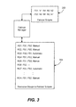
- FIG. 3 shows the node identities for the failover scopes FS1 and FS2 of FIG. 2, with each failover scope identity having a list of node identities that belong to that failover scope, such as maintained in a data structure 302. Also shown is an example set of resource group identifiers RG1-RGn listing their associated failover scopes, such as maintained in another data structure 304.
- a resource group is only failed over to a node listed in its associated failover scope or scopes.
- a resource group is not required to have an association with a failover scope, in which event that resource group can be failed over to any node in the cluster (as long as that node can accept the resource group due to other considerations).
- the resource group can be associated with a failover scope comprising only a single node; if that node fails, there will be no other node to failover the resource group to and an automatic restart process or the administrator will have to restart the node and/or reconfigure the failover scope for that resource group.
- the resource group RG1 is set to first fail over to a node within the first failover scope (FS1) 208 of FIG. 2; only if no node within that failover scope is able to handle the failover will failover to a node in the second failover scope (FS2) 210 be attempted; in other words, precedence is maintained across the failover scopes.
- FS1 first failover scope
- FS2 second failover scope
- another node may be selected from another failaver scope associated with that group based on some criteria other than ordering, e.g., current load, capability to host the resource group, bandwidth, and other metrics. Note that if a node to which a resource group is failed over itself fails, then the failover manager will first try to failover the group to some other node within that failover scope (although all nodes in that scope may be dead).
- a flag controls whether the failover is manual or automatic for a given resource group across failover scopes. That is, when the flag is set to manual, manual intervention is required to bring the resource group online on the surviving failover scope.
- multiple failover scopes are ordered, however the list of nodes in a failover scope need not be ordered. Instead, nodes may be chosen randomly, or in some other appropriate manner, such as based on load-balancing criteria.
- an administrator may set a favored node ordering within a failover scope, such as by selecting according to node ordering and then having different failover scopes for each ordering. For example, if ordered node selection was active, FS1 is shown in FIG. 3 as being ordered as N1, N4, N3, N2; a new failover scope, FS13 (not shown), may be defined with the same nodes N2, N3, N4, N1. The administrator may then associate one resource group with FS1 and another resource group with FS13, whereby the resource groups typically will failover to different nodes, but will still failover within the same subset of nodes.
- the user does not need to set the preferred list for a group, as internally, the cluster nodes are listed in the preferred list in a random order. The nodes that cannot host resources within that group are pruned from this list. However, the user may set the group preferred list to a particular order if the user wishes to have more control over group placement.
- Failover generally works via components represented in FIG. 4, wherein the cluster 202 of FIG. 2 is shown in a slightly different manner, with two of the nodes (N4 and N5) having some of their internal components and data structures revealed, mainly those used for failover. Note that the other nodes N1-N3 and N6-N8 have similar components and data structures, but these internal items are not separately shown. Further consider that node N2 has failed, as indicated by the diagonal lines crossing out the node N2, and thus that the node N2's resource groups need to be failed over. Note that it is possible that a resource group can fail and thus be failed over even though its node is still operating; e.g., a resource group may be moved to another node by intentionally causing a failover, such as for testing purposes.
- each node in the cluster knows of the failure. For example, one way a node failure may be detected is that the failed node stops responding to regular ping messages, or alternately, fails to send out periodic heartbeat messages. As such information is regularly communicated to the nodes of a cluster, the surviving nodes know of the failure.
- one of the nodes is a leader node that controls the failover; (note that if the leader node fails another node accedes as a new leader, so a leader node is always present as there is at least one healthy node in the cluster).
- the leader node controls (or delegates to another node control of) the failover operation to ensure that for each resource group to failover, the failover operation is first attempted according to the failover scope ordering for that resource group.
- each node has a failover manager (sometimes referred to as a resource control manager), along with the data structures maintaining the failover scopes and the resource groups to failover scopes associations.
- the failover manager works to restrict the failover of the resource groups to the nodes contained within the resource group's associated failover scopes, in order of the failover scopes.
- the failover manager is labeled 408 4 , the failover scopes data structure 302 4 and the resource groups-to-failover scopes associations data structure 304 4 , with similar items labeled with subscript "5" for node N5.
- a "resource manager” may provide a hosting environment for a resource, in which event the failover managers provide control orders directed to the resources via their appropriate resource managers.
- the failover manager may enforce rules to ensure that the failover scopes associated with a resource group are non-intersecting, that is, disjoint. Alternatively, if this is not enforced by the failover manager, this is allowed and will work because the failover manager makes decisions based on the configuration. Further, the failover manager may first determine the ability of a node to host a resource group, either automatically if possible, or with some input from the administrator. For example, an automatic decision may be made based on whether a candidate node contains a copy of the resource group's binary code.
- an application corresponding to a resource group may be installed on some nodes of a cluster but not the others; e.g., user input might be necessary in deciding whether an application needs to use some special capabilities (such as multiprocessor support) associated with a subset of nodes.
- some special capabilities such as multiprocessor support
- Failover scopes may be created manually, e.g., by invoking APIs that the cluster runtime supports. As a result, the failover scopes do not necessarily have to represent sites, as described below with reference to FIGS. 5 and 6. Failover scopes may be used to define an island of nodes within which an application can fail over.
- Failover scopes that represent sites may be automatically created because the underlying networking infrastructure has some notion of distance between nodes; note that known algorithms which determine distance based on communication times may be used for distance detection. If the cluster software is so configured, an automated process based on distance detection may add the node to a failover scope that corresponds to a site.
- a component 420 4 (or 420 5 ) that automatically recognizes when a new node is added to a cluster; one such component is a setup program that is run when adding a new node. In this manner, the administrator does not have to update a failover scope for a new node for any failover scope that matches a site.
- the resource groups that are associated with that failover scope need not be changed to be able to run on the new node.
- a cluster may be comprised of multiple sites, (sometimes referred to as a geocluster), with each site comprising a collection of nodes.
- sites sometimes referred to as a geocluster
- the failover scopes configured for a resource group in such a cluster are often defined along site level boundaries, and in practice will likely be used this way. However, implementations of the present invention do not prevent a failover scope from spanning a site.
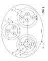
- a failover scope 516 (e.g., the fourth failover scope, FS4) may contain only a subset of the nodes of a site, e.g., only the nodes N2, N3 and N4 of the site 504 are identified in the failover scope FS4.
- a failover scope FS4 may contain only a subset of the nodes of a site, e.g., only the nodes N2, N3 and N4 of the site 504 are identified in the failover scope FS4.
- an attempt will not be made to failover the resource group RG2 to the node N1, because RG2 is associated with failover scope FS4, which does not contain the node N1, as well as the failover scope FS2.
- the manual or automatic flag is not necessarily per resource group, but instead may be per pair of failover scopes within each resource group.
- the resource group RG5 fails over from failover scopes FS1 to FS2 with manual intervention, and then, if necessary, because no suitable or surviving node is found in failover scope FS2, from failover scopes FS2 to FS3, again manually because of the second manual flag.
- the resource group RG7 fails over from failover scopes FS1 to FS2 with manual intervention, but then, if necessary, because no suitable or surviving node is found in failover scope FS2, automatically fails over from failover scopes FS2 to FS3, because of the second flag specifies automatic.
Landscapes
- Engineering & Computer Science (AREA)
- Theoretical Computer Science (AREA)
- Quality & Reliability (AREA)
- Physics & Mathematics (AREA)
- General Engineering & Computer Science (AREA)
- General Physics & Mathematics (AREA)
- Hardware Redundancy (AREA)
- Alarm Systems (AREA)
- Selective Calling Equipment (AREA)
- Transmitters (AREA)
Applications Claiming Priority (1)
| Application Number | Priority Date | Filing Date | Title |
|---|---|---|---|
| US10/962,010 US7451347B2 (en) | 2004-10-08 | 2004-10-08 | Failover scopes for nodes of a computer cluster |
Publications (3)
| Publication Number | Publication Date |
|---|---|
| EP1647890A2 true EP1647890A2 (de) | 2006-04-19 |
| EP1647890A3 EP1647890A3 (de) | 2009-06-03 |
| EP1647890B1 EP1647890B1 (de) | 2010-12-15 |
Family
ID=35810188
Family Applications (1)
| Application Number | Title | Priority Date | Filing Date |
|---|---|---|---|
| EP05108801A Expired - Lifetime EP1647890B1 (de) | 2004-10-08 | 2005-09-23 | Bereiche für die Sicherheitsübertragung von Knoten in einem Clustersystem |
Country Status (8)
| Country | Link |
|---|---|
| US (1) | US7451347B2 (de) |
| EP (1) | EP1647890B1 (de) |
| JP (1) | JP5031218B2 (de) |
| KR (1) | KR101176651B1 (de) |
| CN (1) | CN1758608B (de) |
| AT (1) | ATE491989T1 (de) |
| DE (1) | DE602005025297D1 (de) |
| ES (1) | ES2355262T3 (de) |
Cited By (2)
| Publication number | Priority date | Publication date | Assignee | Title |
|---|---|---|---|---|
| WO2009065796A1 (en) * | 2007-11-23 | 2009-05-28 | International Business Machines Corporation | De-centralized nodal failover handling |
| US11341006B1 (en) | 2020-10-30 | 2022-05-24 | International Business Machines Corporation | Dynamic replacement of degrading processing elements in streaming applications |
Families Citing this family (35)
| Publication number | Priority date | Publication date | Assignee | Title |
|---|---|---|---|---|
| US8046446B1 (en) * | 2004-10-18 | 2011-10-25 | Symantec Operating Corporation | System and method for providing availability using volume server sets in a storage environment employing distributed block virtualization |
| US8316129B2 (en) | 2005-05-25 | 2012-11-20 | Microsoft Corporation | Data communication coordination with sequence numbers |
| US8195976B2 (en) * | 2005-06-29 | 2012-06-05 | International Business Machines Corporation | Fault-tolerance and fault-containment models for zoning clustered application silos into continuous availability and high availability zones in clustered systems during recovery and maintenance |
| US7549079B2 (en) * | 2005-11-30 | 2009-06-16 | Oracle International Corporation | System and method of configuring a database system with replicated data and automatic failover and recovery |
| KR100930576B1 (ko) * | 2006-12-04 | 2009-12-09 | 한국전자통신연구원 | 가상화 기반 고가용성 클러스터 시스템 및 고가용성클러스터 시스템에서 장애 관리 방법 |
| TW200832128A (en) * | 2007-01-26 | 2008-08-01 | Rdc Semiconductor Co Ltd | Redundant system |
| US7757116B2 (en) * | 2007-04-04 | 2010-07-13 | Vision Solutions, Inc. | Method and system for coordinated multiple cluster failover |
| JP2008269462A (ja) * | 2007-04-24 | 2008-11-06 | Hitachi Ltd | ノードの管理装置及び方法 |
| US8984108B2 (en) * | 2007-05-03 | 2015-03-17 | Telefonaktiebolaget L M Ericsson (Publ) | Dynamic CLI mapping for clustered software entities |
| US7716523B2 (en) * | 2007-05-03 | 2010-05-11 | Symantec Corporation | End-to-end transactional protection for requests in a web application |
| US7783813B2 (en) * | 2007-06-14 | 2010-08-24 | International Business Machines Corporation | Multi-node configuration of processor cards connected via processor fabrics |
| JP5008075B2 (ja) * | 2007-07-10 | 2012-08-22 | 国立大学法人大阪大学 | Webサービスシステム |
| US8676760B2 (en) | 2008-08-05 | 2014-03-18 | International Business Machines Corporation | Maintaining data integrity in data servers across data centers |
| US9454444B1 (en) * | 2009-03-19 | 2016-09-27 | Veritas Technologies Llc | Using location tracking of cluster nodes to avoid single points of failure |
| US8055933B2 (en) * | 2009-07-21 | 2011-11-08 | International Business Machines Corporation | Dynamic updating of failover policies for increased application availability |
| US9195528B1 (en) * | 2010-02-24 | 2015-11-24 | Symantec Corporation | Systems and methods for managing failover clusters |
| US8539087B2 (en) * | 2010-03-12 | 2013-09-17 | Symantec Corporation | System and method to define, visualize and manage a composite service group in a high-availability disaster recovery environment |
| US8631277B2 (en) | 2010-12-10 | 2014-01-14 | Microsoft Corporation | Providing transparent failover in a file system |
| US9331955B2 (en) | 2011-06-29 | 2016-05-03 | Microsoft Technology Licensing, Llc | Transporting operations of arbitrary size over remote direct memory access |
| US8856582B2 (en) | 2011-06-30 | 2014-10-07 | Microsoft Corporation | Transparent failover |
| US20130067095A1 (en) | 2011-09-09 | 2013-03-14 | Microsoft Corporation | Smb2 scaleout |
| US8788579B2 (en) | 2011-09-09 | 2014-07-22 | Microsoft Corporation | Clustered client failover |
| US9323628B2 (en) * | 2012-10-09 | 2016-04-26 | Dh2I Company | Instance level server application monitoring, load balancing, and resource allocation |
| US9116860B2 (en) * | 2012-12-14 | 2015-08-25 | Lenovo Enterprise Solutions (Singapore) Pte. Ltd. | Cascading failover of blade servers in a data center |
| US9122652B2 (en) * | 2012-12-17 | 2015-09-01 | Lenovo Enterprise Solutions (Singapore) Pte. Ltd. | Cascading failover of blade servers in a data center |
| CN104301167B (zh) * | 2013-07-19 | 2018-09-04 | 方正宽带网络服务股份有限公司 | 一种监测装置及方法 |
| US9280432B2 (en) | 2014-03-21 | 2016-03-08 | Netapp, Inc. | Providing data integrity in a non-reliable storage behavior |
| US10275326B1 (en) * | 2014-10-31 | 2019-04-30 | Amazon Technologies, Inc. | Distributed computing system failure detection |
| US10509662B1 (en) * | 2014-11-25 | 2019-12-17 | Scale Computing | Virtual devices in a reliable distributed computing system |
| US9684562B2 (en) | 2015-07-21 | 2017-06-20 | International Business Machines Corporation | Automatic serial starting of resource groups on failover based on the prediction of aggregate resource usage |
| US10997197B2 (en) | 2016-09-27 | 2021-05-04 | International Business Machines Corporation | Dependencies between site components across geographic locations |
| JP7485934B2 (ja) * | 2020-06-30 | 2024-05-17 | 富士通株式会社 | 情報処理プログラム、情報処理装置及び情報処理方法 |
| CN111817895B (zh) * | 2020-07-14 | 2023-04-07 | 济南浪潮数据技术有限公司 | 一种主控节点切换方法、装置、设备及存储介质 |
| CN114327826A (zh) * | 2021-12-28 | 2022-04-12 | 中国农业银行股份有限公司 | 调度器管理方法、装置、设备及存储介质 |
| KR102663681B1 (ko) * | 2021-12-30 | 2024-05-14 | 주식회사 클로봇 | 페일 오버 매니저를 포함하는 로봇 관리 시스템, 및 이를 이용한 로봇 관리 방법 |
Citations (2)
| Publication number | Priority date | Publication date | Assignee | Title |
|---|---|---|---|---|
| US6178529B1 (en) | 1997-11-03 | 2001-01-23 | Microsoft Corporation | Method and system for resource monitoring of disparate resources in a server cluster |
| US6718486B1 (en) | 2000-01-26 | 2004-04-06 | David E. Lovejoy | Fault monitor for restarting failed instances of the fault monitor |
Family Cites Families (30)
| Publication number | Priority date | Publication date | Assignee | Title |
|---|---|---|---|---|
| US6673779B2 (en) * | 1996-03-27 | 2004-01-06 | Inspire Pharmaceuticals, Inc. | Method of treating ciliary dyskinesia with dinucleoside polyphosphate compounds or UTP analogues |
| US6319908B1 (en) * | 1996-07-03 | 2001-11-20 | Inspire Pharmaceuticals, Inc. | Method for large-scale production of di(uridine 5′-tetraphosphate) and salts thereof |
| US6696425B2 (en) * | 1997-02-06 | 2004-02-24 | Inspire Pharmaceuticals, Inc. | Method of treating dry eye disease with purinergic receptor agonists |
| US6596725B2 (en) * | 1997-02-10 | 2003-07-22 | Inspire Pharmaceuticals, Inc. | Use of certain dinucleotides to stimulate removal of fluid in retinal detachment and retinal edema |
| US6548658B2 (en) * | 1997-07-25 | 2003-04-15 | Inspire Pharmaceuticals, Inc. | Di-(uridine 5′)-tetraphosphate and salts thereof |
| US6058490A (en) * | 1998-04-21 | 2000-05-02 | Lucent Technologies, Inc. | Method and apparatus for providing scaleable levels of application availability |
| US6438705B1 (en) * | 1999-01-29 | 2002-08-20 | International Business Machines Corporation | Method and apparatus for building and managing multi-clustered computer systems |
| US6857026B1 (en) * | 1999-12-14 | 2005-02-15 | Nortel Networks Limited | Using alternate routes for fail-over in a communication network |
| US6789213B2 (en) * | 2000-01-10 | 2004-09-07 | Sun Microsystems, Inc. | Controlled take over of services by remaining nodes of clustered computing system |
| US20020198996A1 (en) * | 2000-03-16 | 2002-12-26 | Padmanabhan Sreenivasan | Flexible failover policies in high availability computing systems |
| US6990606B2 (en) * | 2000-07-28 | 2006-01-24 | International Business Machines Corporation | Cascading failover of a data management application for shared disk file systems in loosely coupled node clusters |
| US6555675B2 (en) * | 2000-08-21 | 2003-04-29 | Inspire Pharmaceuticals, Inc. | Dinucleoside polyphosphate compositions and their therapuetic use as purinergic receptor agonists |
| US6738923B1 (en) * | 2000-09-07 | 2004-05-18 | International Business Machines Corporation | Network station adjustable fail-over time intervals for booting to backup servers when transport service is not available |
| US6782416B2 (en) * | 2001-01-12 | 2004-08-24 | Hewlett-Packard Development Company, L.P. | Distributed and geographically dispersed quorum resource disks |
| JP4457184B2 (ja) * | 2001-02-13 | 2010-04-28 | ネットアップ,インコーポレイテッド | ストレージシステムにおけるフェイルオーバー処理 |
| CA2437657A1 (en) * | 2001-02-24 | 2002-09-06 | International Business Machines Corporation | Fault isolation through no-overhead link level crc |
| US20040010502A1 (en) * | 2002-07-12 | 2004-01-15 | Bomfim Joanes Depaula | In-memory database for high performance, parallel transaction processing |
| CN1294509C (zh) * | 2002-09-06 | 2007-01-10 | 劲智数位科技股份有限公司 | 具有分布式负载平衡系统的集群计算机 |
| US7188155B2 (en) * | 2002-12-17 | 2007-03-06 | International Business Machines Corporation | Apparatus and method for selecting a web service in response to a request from a client device |
| JP4037257B2 (ja) * | 2002-12-26 | 2008-01-23 | 株式会社日立製作所 | 情報処理システムの制御方法、情報処理システム、及びプログラム |
| US7137040B2 (en) * | 2003-02-12 | 2006-11-14 | International Business Machines Corporation | Scalable method of continuous monitoring the remotely accessible resources against the node failures for very large clusters |
| US7134046B2 (en) * | 2003-03-19 | 2006-11-07 | Lucent Technologies Inc. | Method and apparatus for high availability distributed processing across independent networked computer fault groups |
| JP2005018510A (ja) * | 2003-06-27 | 2005-01-20 | Hitachi Ltd | データセンタシステム及びその制御方法 |
| US7278048B2 (en) * | 2003-07-16 | 2007-10-02 | Lucent Technologies Inc. | Method, system and computer program product for improving system reliability |
| US7234073B1 (en) * | 2003-09-30 | 2007-06-19 | Emc Corporation | System and methods for failover management of manageable entity agents |
| US7225356B2 (en) * | 2003-11-06 | 2007-05-29 | Siemens Medical Solutions Health Services Corporation | System for managing operational failure occurrences in processing devices |
| JP4420275B2 (ja) * | 2003-11-12 | 2010-02-24 | 株式会社日立製作所 | フェイルオーバクラスタシステム及びフェイルオーバクラスタシステムを用いたプログラムのインストール方法 |
| US7188273B2 (en) * | 2003-11-24 | 2007-03-06 | Tsx Inc. | System and method for failover |
| US20050193104A1 (en) * | 2004-02-27 | 2005-09-01 | Wyse Technology Inc. | User interface for remote computing devices |
| JP4462969B2 (ja) * | 2004-03-12 | 2010-05-12 | 株式会社日立製作所 | フェイルオーバクラスタシステム及びフェイルオーバ方法 |
-
2004
- 2004-10-08 US US10/962,010 patent/US7451347B2/en active Active
-
2005
- 2005-09-21 KR KR1020050087690A patent/KR101176651B1/ko not_active Expired - Fee Related
- 2005-09-23 ES ES05108801T patent/ES2355262T3/es not_active Expired - Lifetime
- 2005-09-23 AT AT05108801T patent/ATE491989T1/de not_active IP Right Cessation
- 2005-09-23 EP EP05108801A patent/EP1647890B1/de not_active Expired - Lifetime
- 2005-09-23 DE DE602005025297T patent/DE602005025297D1/de not_active Expired - Lifetime
- 2005-09-29 CN CN2005101089884A patent/CN1758608B/zh not_active Expired - Fee Related
- 2005-10-11 JP JP2005296642A patent/JP5031218B2/ja not_active Expired - Fee Related
Patent Citations (2)
| Publication number | Priority date | Publication date | Assignee | Title |
|---|---|---|---|---|
| US6178529B1 (en) | 1997-11-03 | 2001-01-23 | Microsoft Corporation | Method and system for resource monitoring of disparate resources in a server cluster |
| US6718486B1 (en) | 2000-01-26 | 2004-04-06 | David E. Lovejoy | Fault monitor for restarting failed instances of the fault monitor |
Cited By (2)
| Publication number | Priority date | Publication date | Assignee | Title |
|---|---|---|---|---|
| WO2009065796A1 (en) * | 2007-11-23 | 2009-05-28 | International Business Machines Corporation | De-centralized nodal failover handling |
| US11341006B1 (en) | 2020-10-30 | 2022-05-24 | International Business Machines Corporation | Dynamic replacement of degrading processing elements in streaming applications |
Also Published As
| Publication number | Publication date |
|---|---|
| ATE491989T1 (de) | 2011-01-15 |
| ES2355262T3 (es) | 2011-03-24 |
| US7451347B2 (en) | 2008-11-11 |
| EP1647890B1 (de) | 2010-12-15 |
| EP1647890A3 (de) | 2009-06-03 |
| KR20060051477A (ko) | 2006-05-19 |
| CN1758608A (zh) | 2006-04-12 |
| JP5031218B2 (ja) | 2012-09-19 |
| US20060080568A1 (en) | 2006-04-13 |
| JP2006114040A (ja) | 2006-04-27 |
| CN1758608B (zh) | 2011-08-17 |
| DE602005025297D1 (de) | 2011-01-27 |
| KR101176651B1 (ko) | 2012-08-23 |
Similar Documents
| Publication | Publication Date | Title |
|---|---|---|
| EP1647890B1 (de) | Bereiche für die Sicherheitsübertragung von Knoten in einem Clustersystem | |
| US9037899B2 (en) | Automated node fencing integrated within a quorum service of a cluster infrastructure | |
| US7971089B2 (en) | Switching connection of a boot disk to a substitute server and moving the failed server to a server domain pool | |
| US6243825B1 (en) | Method and system for transparently failing over a computer name in a server cluster | |
| US9405640B2 (en) | Flexible failover policies in high availability computing systems | |
| US7225356B2 (en) | System for managing operational failure occurrences in processing devices | |
| US6839752B1 (en) | Group data sharing during membership change in clustered computer system | |
| US7370336B2 (en) | Distributed computing infrastructure including small peer-to-peer applications | |
| US20130159487A1 (en) | Migration of Virtual IP Addresses in a Failover Cluster | |
| US10069688B2 (en) | Dynamically assigning, by functional domain, separate pairs of servers to primary and backup service processor modes within a grouping of servers | |
| US20080244068A1 (en) | Computer product, operation management method, and operation management apparatus | |
| US7246261B2 (en) | Join protocol for a primary-backup group with backup resources in clustered computer system | |
| US20070237162A1 (en) | Method, apparatus, and computer product for processing resource change | |
| JP2005056392A (ja) | 地理的ミラーリングに関するリソースの妥当性検査およびランキングのための方法および装置 | |
| JP4287092B2 (ja) | ファイル管理システムおよびファイル管理方法 | |
| US20030005080A1 (en) | Systems and methods for accessing data | |
| JP4910274B2 (ja) | プログラム及びサーバ装置 | |
| US7558858B1 (en) | High availability infrastructure with active-active designs | |
| JP3314665B2 (ja) | 分散ファイルシステム | |
| CN115001950A (zh) | 一种数据库集群的故障处理方法、存储介质与设备 |
Legal Events
| Date | Code | Title | Description |
|---|---|---|---|
| PUAI | Public reference made under article 153(3) epc to a published international application that has entered the european phase |
Free format text: ORIGINAL CODE: 0009012 |
|
| AK | Designated contracting states |
Kind code of ref document: A2 Designated state(s): AT BE BG CH CY CZ DE DK EE ES FI FR GB GR HU IE IS IT LI LT LU LV MC NL PL PT RO SE SI SK TR |
|
| AX | Request for extension of the european patent |
Extension state: AL BA HR MK YU |
|
| PUAL | Search report despatched |
Free format text: ORIGINAL CODE: 0009013 |
|
| AK | Designated contracting states |
Kind code of ref document: A3 Designated state(s): AT BE BG CH CY CZ DE DK EE ES FI FR GB GR HU IE IS IT LI LT LU LV MC NL PL PT RO SE SI SK TR |
|
| AX | Request for extension of the european patent |
Extension state: AL BA HR MK YU |
|
| 17P | Request for examination filed |
Effective date: 20091026 |
|
| 17Q | First examination report despatched |
Effective date: 20091120 |
|
| AKX | Designation fees paid |
Designated state(s): AT BE BG CH CY CZ DE DK EE ES FI FR GB GR HU IE IS IT LI LT LU LV MC NL PL PT RO SE SI SK TR |
|
| GRAP | Despatch of communication of intention to grant a patent |
Free format text: ORIGINAL CODE: EPIDOSNIGR1 |
|
| GRAS | Grant fee paid |
Free format text: ORIGINAL CODE: EPIDOSNIGR3 |
|
| GRAA | (expected) grant |
Free format text: ORIGINAL CODE: 0009210 |
|
| AK | Designated contracting states |
Kind code of ref document: B1 Designated state(s): AT BE BG CH CY CZ DE DK EE ES FI FR GB GR HU IE IS IT LI LT LU LV MC NL PL PT RO SE SI SK TR |
|
| REG | Reference to a national code |
Ref country code: CH Ref legal event code: EP Ref country code: GB Ref legal event code: FG4D |
|
| REG | Reference to a national code |
Ref country code: IE Ref legal event code: FG4D |
|
| REF | Corresponds to: |
Ref document number: 602005025297 Country of ref document: DE Date of ref document: 20110127 Kind code of ref document: P |
|
| REG | Reference to a national code |
Ref country code: ES Ref legal event code: FG2A Ref document number: 2355262 Country of ref document: ES Kind code of ref document: T3 Effective date: 20110324 |
|
| REG | Reference to a national code |
Ref country code: NL Ref legal event code: VDEP Effective date: 20101215 |
|
| PG25 | Lapsed in a contracting state [announced via postgrant information from national office to epo] |
Ref country code: LT Free format text: LAPSE BECAUSE OF FAILURE TO SUBMIT A TRANSLATION OF THE DESCRIPTION OR TO PAY THE FEE WITHIN THE PRESCRIBED TIME-LIMIT Effective date: 20101215 |
|
| LTIE | Lt: invalidation of european patent or patent extension |
Effective date: 20101215 |
|
| PG25 | Lapsed in a contracting state [announced via postgrant information from national office to epo] |
Ref country code: AT Free format text: LAPSE BECAUSE OF FAILURE TO SUBMIT A TRANSLATION OF THE DESCRIPTION OR TO PAY THE FEE WITHIN THE PRESCRIBED TIME-LIMIT Effective date: 20101215 Ref country code: SI Free format text: LAPSE BECAUSE OF FAILURE TO SUBMIT A TRANSLATION OF THE DESCRIPTION OR TO PAY THE FEE WITHIN THE PRESCRIBED TIME-LIMIT Effective date: 20101215 Ref country code: BG Free format text: LAPSE BECAUSE OF FAILURE TO SUBMIT A TRANSLATION OF THE DESCRIPTION OR TO PAY THE FEE WITHIN THE PRESCRIBED TIME-LIMIT Effective date: 20110315 Ref country code: FI Free format text: LAPSE BECAUSE OF FAILURE TO SUBMIT A TRANSLATION OF THE DESCRIPTION OR TO PAY THE FEE WITHIN THE PRESCRIBED TIME-LIMIT Effective date: 20101215 Ref country code: NL Free format text: LAPSE BECAUSE OF FAILURE TO SUBMIT A TRANSLATION OF THE DESCRIPTION OR TO PAY THE FEE WITHIN THE PRESCRIBED TIME-LIMIT Effective date: 20101215 Ref country code: LV Free format text: LAPSE BECAUSE OF FAILURE TO SUBMIT A TRANSLATION OF THE DESCRIPTION OR TO PAY THE FEE WITHIN THE PRESCRIBED TIME-LIMIT Effective date: 20101215 Ref country code: SE Free format text: LAPSE BECAUSE OF FAILURE TO SUBMIT A TRANSLATION OF THE DESCRIPTION OR TO PAY THE FEE WITHIN THE PRESCRIBED TIME-LIMIT Effective date: 20101215 Ref country code: CY Free format text: LAPSE BECAUSE OF FAILURE TO SUBMIT A TRANSLATION OF THE DESCRIPTION OR TO PAY THE FEE WITHIN THE PRESCRIBED TIME-LIMIT Effective date: 20101215 |
|
| PG25 | Lapsed in a contracting state [announced via postgrant information from national office to epo] |
Ref country code: BE Free format text: LAPSE BECAUSE OF FAILURE TO SUBMIT A TRANSLATION OF THE DESCRIPTION OR TO PAY THE FEE WITHIN THE PRESCRIBED TIME-LIMIT Effective date: 20101215 Ref country code: EE Free format text: LAPSE BECAUSE OF FAILURE TO SUBMIT A TRANSLATION OF THE DESCRIPTION OR TO PAY THE FEE WITHIN THE PRESCRIBED TIME-LIMIT Effective date: 20101215 Ref country code: CZ Free format text: LAPSE BECAUSE OF FAILURE TO SUBMIT A TRANSLATION OF THE DESCRIPTION OR TO PAY THE FEE WITHIN THE PRESCRIBED TIME-LIMIT Effective date: 20101215 Ref country code: IS Free format text: LAPSE BECAUSE OF FAILURE TO SUBMIT A TRANSLATION OF THE DESCRIPTION OR TO PAY THE FEE WITHIN THE PRESCRIBED TIME-LIMIT Effective date: 20110415 Ref country code: GR Free format text: LAPSE BECAUSE OF FAILURE TO SUBMIT A TRANSLATION OF THE DESCRIPTION OR TO PAY THE FEE WITHIN THE PRESCRIBED TIME-LIMIT Effective date: 20110316 Ref country code: PT Free format text: LAPSE BECAUSE OF FAILURE TO SUBMIT A TRANSLATION OF THE DESCRIPTION OR TO PAY THE FEE WITHIN THE PRESCRIBED TIME-LIMIT Effective date: 20110415 |
|
| PG25 | Lapsed in a contracting state [announced via postgrant information from national office to epo] |
Ref country code: SK Free format text: LAPSE BECAUSE OF FAILURE TO SUBMIT A TRANSLATION OF THE DESCRIPTION OR TO PAY THE FEE WITHIN THE PRESCRIBED TIME-LIMIT Effective date: 20101215 Ref country code: PL Free format text: LAPSE BECAUSE OF FAILURE TO SUBMIT A TRANSLATION OF THE DESCRIPTION OR TO PAY THE FEE WITHIN THE PRESCRIBED TIME-LIMIT Effective date: 20101215 Ref country code: RO Free format text: LAPSE BECAUSE OF FAILURE TO SUBMIT A TRANSLATION OF THE DESCRIPTION OR TO PAY THE FEE WITHIN THE PRESCRIBED TIME-LIMIT Effective date: 20101215 |
|
| PLBE | No opposition filed within time limit |
Free format text: ORIGINAL CODE: 0009261 |
|
| STAA | Information on the status of an ep patent application or granted ep patent |
Free format text: STATUS: NO OPPOSITION FILED WITHIN TIME LIMIT |
|
| PG25 | Lapsed in a contracting state [announced via postgrant information from national office to epo] |
Ref country code: DK Free format text: LAPSE BECAUSE OF FAILURE TO SUBMIT A TRANSLATION OF THE DESCRIPTION OR TO PAY THE FEE WITHIN THE PRESCRIBED TIME-LIMIT Effective date: 20101215 |
|
| 26N | No opposition filed |
Effective date: 20110916 |
|
| PG25 | Lapsed in a contracting state [announced via postgrant information from national office to epo] |
Ref country code: IT Free format text: LAPSE BECAUSE OF FAILURE TO SUBMIT A TRANSLATION OF THE DESCRIPTION OR TO PAY THE FEE WITHIN THE PRESCRIBED TIME-LIMIT Effective date: 20101215 |
|
| REG | Reference to a national code |
Ref country code: DE Ref legal event code: R097 Ref document number: 602005025297 Country of ref document: DE Effective date: 20110916 |
|
| PGFP | Annual fee paid to national office [announced via postgrant information from national office to epo] |
Ref country code: ES Payment date: 20111017 Year of fee payment: 7 |
|
| PG25 | Lapsed in a contracting state [announced via postgrant information from national office to epo] |
Ref country code: MC Free format text: LAPSE BECAUSE OF NON-PAYMENT OF DUE FEES Effective date: 20110930 |
|
| REG | Reference to a national code |
Ref country code: CH Ref legal event code: PL |
|
| REG | Reference to a national code |
Ref country code: IE Ref legal event code: MM4A |
|
| PG25 | Lapsed in a contracting state [announced via postgrant information from national office to epo] |
Ref country code: CH Free format text: LAPSE BECAUSE OF NON-PAYMENT OF DUE FEES Effective date: 20110930 Ref country code: LI Free format text: LAPSE BECAUSE OF NON-PAYMENT OF DUE FEES Effective date: 20110930 Ref country code: IE Free format text: LAPSE BECAUSE OF NON-PAYMENT OF DUE FEES Effective date: 20110923 |
|
| PG25 | Lapsed in a contracting state [announced via postgrant information from national office to epo] |
Ref country code: LU Free format text: LAPSE BECAUSE OF NON-PAYMENT OF DUE FEES Effective date: 20110923 |
|
| PG25 | Lapsed in a contracting state [announced via postgrant information from national office to epo] |
Ref country code: TR Free format text: LAPSE BECAUSE OF FAILURE TO SUBMIT A TRANSLATION OF THE DESCRIPTION OR TO PAY THE FEE WITHIN THE PRESCRIBED TIME-LIMIT Effective date: 20101215 |
|
| REG | Reference to a national code |
Ref country code: ES Ref legal event code: FD2A Effective date: 20131023 |
|
| PG25 | Lapsed in a contracting state [announced via postgrant information from national office to epo] |
Ref country code: HU Free format text: LAPSE BECAUSE OF FAILURE TO SUBMIT A TRANSLATION OF THE DESCRIPTION OR TO PAY THE FEE WITHIN THE PRESCRIBED TIME-LIMIT Effective date: 20101215 |
|
| PG25 | Lapsed in a contracting state [announced via postgrant information from national office to epo] |
Ref country code: ES Free format text: LAPSE BECAUSE OF NON-PAYMENT OF DUE FEES Effective date: 20120924 |
|
| REG | Reference to a national code |
Ref country code: DE Ref legal event code: R082 Ref document number: 602005025297 Country of ref document: DE Representative=s name: GRUENECKER, KINKELDEY, STOCKMAIR & SCHWANHAEUS, DE |
|
| REG | Reference to a national code |
Ref country code: GB Ref legal event code: 732E Free format text: REGISTERED BETWEEN 20150115 AND 20150121 |
|
| REG | Reference to a national code |
Ref country code: DE Ref legal event code: R082 Ref document number: 602005025297 Country of ref document: DE Representative=s name: GRUENECKER PATENT- UND RECHTSANWAELTE PARTG MB, DE Effective date: 20150126 Ref country code: DE Ref legal event code: R081 Ref document number: 602005025297 Country of ref document: DE Owner name: MICROSOFT TECHNOLOGY LICENSING, LLC, REDMOND, US Free format text: FORMER OWNER: MICROSOFT CORP., REDMOND, WASH., US Effective date: 20150126 |
|
| REG | Reference to a national code |
Ref country code: FR Ref legal event code: TP Owner name: MICROSOFT TECHNOLOGY LICENSING, LLC, US Effective date: 20150724 |
|
| REG | Reference to a national code |
Ref country code: FR Ref legal event code: PLFP Year of fee payment: 12 |
|
| REG | Reference to a national code |
Ref country code: FR Ref legal event code: PLFP Year of fee payment: 13 |
|
| REG | Reference to a national code |
Ref country code: FR Ref legal event code: PLFP Year of fee payment: 14 |
|
| PGFP | Annual fee paid to national office [announced via postgrant information from national office to epo] |
Ref country code: DE Payment date: 20180911 Year of fee payment: 14 Ref country code: FR Payment date: 20180813 Year of fee payment: 14 |
|
| PGFP | Annual fee paid to national office [announced via postgrant information from national office to epo] |
Ref country code: GB Payment date: 20180919 Year of fee payment: 14 |
|
| REG | Reference to a national code |
Ref country code: DE Ref legal event code: R119 Ref document number: 602005025297 Country of ref document: DE |
|
| PG25 | Lapsed in a contracting state [announced via postgrant information from national office to epo] |
Ref country code: DE Free format text: LAPSE BECAUSE OF NON-PAYMENT OF DUE FEES Effective date: 20200401 |
|
| GBPC | Gb: european patent ceased through non-payment of renewal fee |
Effective date: 20190923 |
|
| PG25 | Lapsed in a contracting state [announced via postgrant information from national office to epo] |
Ref country code: GB Free format text: LAPSE BECAUSE OF NON-PAYMENT OF DUE FEES Effective date: 20190923 Ref country code: FR Free format text: LAPSE BECAUSE OF NON-PAYMENT OF DUE FEES Effective date: 20190930 |