EP1648372B1 - Anlage mit einer maschine für die herstellung von tabletten, die besonders für die therapeutische anwendung bestimmt sind - Google Patents
Anlage mit einer maschine für die herstellung von tabletten, die besonders für die therapeutische anwendung bestimmt sind Download PDFInfo
- Publication number
- EP1648372B1 EP1648372B1 EP04767599A EP04767599A EP1648372B1 EP 1648372 B1 EP1648372 B1 EP 1648372B1 EP 04767599 A EP04767599 A EP 04767599A EP 04767599 A EP04767599 A EP 04767599A EP 1648372 B1 EP1648372 B1 EP 1648372B1
- Authority
- EP
- European Patent Office
- Prior art keywords
- enclosure
- gas
- installation according
- temperature
- machine
- Prior art date
- Legal status (The legal status is an assumption and is not a legal conclusion. Google has not performed a legal analysis and makes no representation as to the accuracy of the status listed.)
- Expired - Lifetime
Links
- 238000009434 installation Methods 0.000 title claims abstract description 51
- 238000004519 manufacturing process Methods 0.000 title claims abstract description 17
- 230000001225 therapeutic effect Effects 0.000 title claims description 7
- 238000011144 upstream manufacturing Methods 0.000 claims description 15
- 238000001816 cooling Methods 0.000 claims description 13
- 238000010438 heat treatment Methods 0.000 claims description 9
- HEFNNWSXXWATRW-UHFFFAOYSA-N Ibuprofen Chemical compound CC(C)CC1=CC=C(C(C)C(O)=O)C=C1 HEFNNWSXXWATRW-UHFFFAOYSA-N 0.000 claims description 8
- 229960001680 ibuprofen Drugs 0.000 claims description 8
- 239000000126 substance Substances 0.000 claims description 7
- 238000004891 communication Methods 0.000 claims description 5
- 238000000034 method Methods 0.000 claims description 5
- 239000002537 cosmetic Substances 0.000 claims description 4
- 239000002245 particle Substances 0.000 claims description 3
- 230000006835 compression Effects 0.000 description 37
- 238000007906 compression Methods 0.000 description 37
- 238000007664 blowing Methods 0.000 description 17
- 238000009792 diffusion process Methods 0.000 description 6
- XLYOFNOQVPJJNP-UHFFFAOYSA-N water Substances O XLYOFNOQVPJJNP-UHFFFAOYSA-N 0.000 description 5
- 238000000605 extraction Methods 0.000 description 4
- 210000000056 organ Anatomy 0.000 description 4
- 239000000843 powder Substances 0.000 description 4
- 239000000523 sample Substances 0.000 description 4
- 238000009530 blood pressure measurement Methods 0.000 description 3
- 230000001276 controlling effect Effects 0.000 description 3
- 238000001914 filtration Methods 0.000 description 3
- 239000000314 lubricant Substances 0.000 description 3
- 229910001220 stainless steel Inorganic materials 0.000 description 3
- 239000010935 stainless steel Substances 0.000 description 3
- 238000011109 contamination Methods 0.000 description 2
- 238000007791 dehumidification Methods 0.000 description 2
- 230000001627 detrimental effect Effects 0.000 description 2
- 238000009826 distribution Methods 0.000 description 2
- 238000010410 dusting Methods 0.000 description 2
- 238000012544 monitoring process Methods 0.000 description 2
- 230000001105 regulatory effect Effects 0.000 description 2
- 238000004026 adhesive bonding Methods 0.000 description 1
- 238000005056 compaction Methods 0.000 description 1
- 238000009833 condensation Methods 0.000 description 1
- 230000005494 condensation Effects 0.000 description 1
- 230000003750 conditioning effect Effects 0.000 description 1
- 239000000470 constituent Substances 0.000 description 1
- 238000004320 controlled atmosphere Methods 0.000 description 1
- 239000012809 cooling fluid Substances 0.000 description 1
- 238000013461 design Methods 0.000 description 1
- 238000010586 diagram Methods 0.000 description 1
- 238000006073 displacement reaction Methods 0.000 description 1
- 239000000428 dust Substances 0.000 description 1
- 235000021183 entrée Nutrition 0.000 description 1
- 239000010687 lubricating oil Substances 0.000 description 1
- 238000005461 lubrication Methods 0.000 description 1
- 238000002844 melting Methods 0.000 description 1
- 230000008018 melting Effects 0.000 description 1
- 239000002184 metal Substances 0.000 description 1
- 239000000203 mixture Substances 0.000 description 1
- 238000012986 modification Methods 0.000 description 1
- 230000004048 modification Effects 0.000 description 1
- 230000010355 oscillation Effects 0.000 description 1
- 238000005192 partition Methods 0.000 description 1
- 230000003449 preventive effect Effects 0.000 description 1
- 239000002994 raw material Substances 0.000 description 1
- 238000005057 refrigeration Methods 0.000 description 1
- 238000007493 shaping process Methods 0.000 description 1
- 238000004513 sizing Methods 0.000 description 1
- 238000005507 spraying Methods 0.000 description 1
- 238000011282 treatment Methods 0.000 description 1
- 239000003039 volatile agent Substances 0.000 description 1
Images



Classifications
-
- B—PERFORMING OPERATIONS; TRANSPORTING
- B30—PRESSES
- B30B—PRESSES IN GENERAL
- B30B15/00—Details of, or accessories for, presses; Auxiliary measures in connection with pressing
- B30B15/0082—Dust eliminating means; Mould or press ram cleaning means
-
- A—HUMAN NECESSITIES
- A61—MEDICAL OR VETERINARY SCIENCE; HYGIENE
- A61J—CONTAINERS SPECIALLY ADAPTED FOR MEDICAL OR PHARMACEUTICAL PURPOSES; DEVICES OR METHODS SPECIALLY ADAPTED FOR BRINGING PHARMACEUTICAL PRODUCTS INTO PARTICULAR PHYSICAL OR ADMINISTERING FORMS; DEVICES FOR ADMINISTERING FOOD OR MEDICINES ORALLY; BABY COMFORTERS; DEVICES FOR RECEIVING SPITTLE
- A61J3/00—Devices or methods specially adapted for bringing pharmaceutical products into particular physical or administering forms
- A61J3/10—Devices or methods specially adapted for bringing pharmaceutical products into particular physical or administering forms into the form of compressed tablets
-
- B—PERFORMING OPERATIONS; TRANSPORTING
- B30—PRESSES
- B30B—PRESSES IN GENERAL
- B30B11/00—Presses specially adapted for forming shaped articles from material in particulate or plastic state, e.g. briquetting presses, tabletting presses
- B30B11/005—Control arrangements
-
- B—PERFORMING OPERATIONS; TRANSPORTING
- B30—PRESSES
- B30B—PRESSES IN GENERAL
- B30B11/00—Presses specially adapted for forming shaped articles from material in particulate or plastic state, e.g. briquetting presses, tabletting presses
- B30B11/02—Presses specially adapted for forming shaped articles from material in particulate or plastic state, e.g. briquetting presses, tabletting presses using a ram exerting pressure on the material in a moulding space
- B30B11/08—Presses specially adapted for forming shaped articles from material in particulate or plastic state, e.g. briquetting presses, tabletting presses using a ram exerting pressure on the material in a moulding space co-operating with moulds carried by a turntable
-
- B—PERFORMING OPERATIONS; TRANSPORTING
- B30—PRESSES
- B30B—PRESSES IN GENERAL
- B30B15/00—Details of, or accessories for, presses; Auxiliary measures in connection with pressing
- B30B15/34—Heating or cooling presses or parts thereof
Definitions
- the invention relates to the manufacture of tablets, in particular tablets comprising a substance for therapeutic or cosmetic use.
- tablets comprising a substance for therapeutic or cosmetic use.
- These include, for example, tablets comprising ibuprofen.
- the ibuprofen molecule has a softening point at 42 ° C and a melting point at 70 ° C. It is known to form ibuprofen tablets from a powder by means of a machine comprising a series of dies and punches between which the tablets are formed. Within the machine, the compression dynamics generate temperature rises, which causes a softening of the raw material used for the production of tablets. This can result in a problem of sticking of the powder or tablets within the machine, which is detrimental to its proper functioning.
- the document FR-2 440188 discloses to figure 3 a tabletting machine, some of whose parts have internal channels through which a cooling fluid passes. Such cooling means must be taken into account from the design and manufacture of the machine, so that this method can not be implemented on an existing machine without heavy modifications thereof.
- the document provides to enclose the entire machine in an enclosure comprising a gas whose temperature is controlled. But the energy spent to maintain the temperature of the gas, and therefore the temperature of the machine, to the desired level is very high.
- the document DE-A-2363921 discloses a tabletting machine having an enclosure which includes means for controlling the temperature of the gas flowing in the enclosure.
- An object of the invention is to solve the problem of gluing during the manufacture of tablets by means easily adaptable to an existing machine and whose implementation does not require a high energy expenditure.
- an installation comprising a machine for producing tablets, the machine having at least an enclosure, the installation comprising means for bringing a gas into the enclosure and make it go through the enclosure.
- the invention can be easily adapted to an existing machine without excessive cost.
- the circulation of the gas in the enclosure allows to cool it effectively without excessive energy expenditure.
- said means are arranged to control a temperature of the gas.
- said means are arranged to control a hygrometry of the gas.
- the hygrometry of the gas surrounding the machine is an equally important parameter to avoid sticking during manufacture.
- Also provided according to the invention is a method of manufacturing tablets in which a gas is introduced into a chamber forming part of a tablet making machine, and is made to traverse the enclosure.
- the installation 2 comprises a machine 4 which is used for the production of tablets for therapeutic use comprising ibuprofen, this machine being of a type known in itself.
- a machine 4 which is used for the production of tablets for therapeutic use comprising ibuprofen, this machine being of a type known in itself.
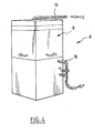
- it conventionally comprises a compression chamber 6 enclosing tablet production members, a motor frame 8 including in particular a motor actuating the organs located in the enclosure of compression, and an electronic frame 10 ensuring the regulation of the machine.
- the compression chamber, the motor frame, and the electronic frame are contiguous to each other and enclosed in a common housing.
- Such a machine is for example of the type disclosed in the document FR-2 440188 above and will not be described below in detail in all its constituent parts.
- the installation 2 comprises in this case means for cooling the machine 4 by blowing cooled air. It comprises in particular an upstream blower 9. It also includes an air handling unit 12 ensuring in this case the filtration, dehumidification and possibly the heating or cooling of the air. It comprises a downstream exhaust fan 14. Finally, it comprises ducts or ducts 16, for example made of stainless steel, putting the different parts of the installation in communication with gas 2. Thus a first common duct 16 extends downstream of the air handling unit and communicates with three other ducts connected in parallel connection to the compression chamber 6, the motor frame 8, and the electronic frame 10 respectively. Finally, two ducts 16 are arranged in a parallel arrangement downstream respectively of the motor frame and the electronic frame. They communicate with a common sheath 16, itself in communication with the downstream blower 14.
- the air is brought to three points of the tablet press 4. It is first brought into the compression chamber 6 as close as possible to the production members to bring about frigories allowing to combat the calories generated by the rapid displacement of the manufacturing turret and friction.
- the air is also brought into the motor frame 8 in order to minimize the heat diffusion phenomena in the direction of the adjacent compression chamber, phenomena due to the heating of the mechanical elements of the engine.
- the supply of frigories in the electronic frame 10 makes it possible to minimize the phenomena of heat diffusion towards the motor frame and the compression chamber, phenomena due to heating of electrical and electronic components.
- the air handling unit 12 is preferably installed in a different technical room of the local receiving the tablet 4.
- This plant ensures the conditioning of the air blown. It ensures the control of the particulate quality by filtration, dehumidification, and if necessary the heating and / or cooling of the air. It is in this case a central Hydronic brand CCM20 type that can provide an air flow of 1500 m 3 / hour and with an available pressure of 350 Pa. In this example, this plant operates in all fresh air, that is to say that it does not receive air having already passed through the machine.
- the plant comprises a type 20 F6 particle filter (according to the EN779 standard). Downstream of the filter 20, the plant firstly comprises an electric hot-air battery 22 with a power of 7.8 kW, then a battery 24 operating with iced water having a temperature between 0 and 5 ° C. a power of 24 kW. It is followed by a second battery of chilled water 26. There is then a hot electric battery 28 with a power of 15.6 kW.
- the plant comprises, downstream of these elements, the above-mentioned upstream blower 9 which, in the present example, is therefore integrated into the plant and provides a flow rate of 1500 m 3 / hour by providing an available pressure of 300 Pa.
- the upstream blower 9 which, in the present example, is therefore integrated into the plant and provides a flow rate of 1500 m 3 / hour by providing an available pressure of 300 Pa.
- All these filters have the particular function of making the gas "clean" that is to say, compatible with a pharmaceutical use to allow it to come into contact with the tablets.
- the sizing calculations of the machine were made according to different climatic and geographical data. Thus, it is desired in summer and winter to maintain in the machine a vacuum of 0 to 30 Pa, a temperature in the compression turret of 25 ° C and a humidity of the blowing air of less than 5 g of water per kg dry air. Winter conditions were assumed to be - 7 ° C with 90% relative humidity and in summer an outdoor temperature of 29 ° C with 43% relative humidity.
- Each cold battery 24, 26 of the central unit 12 is fed by a common chilled water circuit connected to a refrigeration unit 34 illustrated in FIG. figure 3 .
- This group is associated with buffer tanks respectively of 100 liters and 300 liters to ensure a high stability in the accuracy of the temperature of the water.
- a blowing register 36a, 36b and 36c On the path of each of these last three sheaths is positioned a blowing register 36a, 36b and 36c.
- This is a motorized register 36a on the path to the compression chamber.
- the registers 36b and 36c on the path to the motor and electronic frames are not motorized.
- the motorized damper 36a makes it possible to seal the compression chamber with respect to the air blowing network in the event of the machine being stopped. This is a pharmaceutical constraint to prevent contamination of the blowing network by the powder present in the machine.
- Each of these registers also makes it possible to modify the air flow rate in each of the ducts 16 associated to vary this flow rate between different non-zero flow rate values, or even to completely close the duct.
- the sheaths 16 are in this case made of stainless steel AISI 316 L.
- each of these three ducts leaves the local receiving the central 12 and ends in the room housing the tablet 4. This room is controlled atmosphere.
- each of these three sheaths 16 has a removable central part, and two parts respectively upstream and downstream located on either side of the removable part and permanently attached respectively to the room and the machine.
- the presence of these removable sections allows to use if necessary the machine 4 in its original configuration, to have without implementing the cooling air blowing.
- plugs for example stainless steel, are positioned on the fixed sheath sections associated with the machine in order to ensure the basic performance of the machine.
- the sheath 16 associated with the compression chamber 6 arrives from above the enclosure. It makes it possible to diffuse the air as close as possible to the compression matrices 39.
- a box or deflector 40 in the form of a rectangular parallelepiped and made of sheet metal. This box receives air coming from the sheath 16. It has openings 42 on its vertical lateral faces 44 and 46, as well as on its lower 48 and rear faces (not shown). It allows a good distribution of the air flow to ensure a perfect diffusion of air inside the compression chamber.
- the front face 49 of the baffle does not have an air outlet opening. Indeed, this face faces the inside of the chamber 6.
- the compressor is also equipped with a pulverulent lubricant spraying system that ensures the lubrication of the dies 39 in a manner known per se and which is a very volatile compound. If this face of the box was not clogged, the blown air would cause a cloud of powdered lubricant within the chamber 6 which would be detrimental to manufacture.
- the deflector 40 extends in the upper part of the enclosure 6. The duct 16 downstream, to extract the gas from the chamber 6, opens in the lower part of the enclosure on a face of this chamber opposite the deflector.
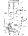
- FIGS. Figures 6 and 7 The cooling means of the enclosure associated with the motor frame 8 are illustrated in FIGS. Figures 6 and 7 .
- the air is sent directly into the engine frame in order to reduce the temperature of this frame and thus minimize the heat diffusion from the engine mount to the compression chamber 6.
- a box 50 or deflector, also made of perforated plate, is installed inside the enclosure 8 of the engine mount.
- the deflector is placed on the lower horizontal face of the enclosure 8 and is open on its upper faces 52, 54 before and vertical side 56 having on each of them an array of orifices 42.
- the sheath 16 of output of air is disposed on a different face of the face of the enclosure 8 receiving the air inlet duct to the deflector.
- the air is brought from below an electrical cabinet 60 of the electronic rack 10.
- a deflector or box is provided for the introduction of air within the enclosure 10.
- the baffle is set up in the lower part of the enclosure after disassembling the fans generally located in the lower part of the cabinet.
- the box is open on its upper face by having several networks of openings 42. This system allows a good distribution of the air flow to ensure a perfect diffusion of air inside the electronic frame.
- the duct 16 upstream introducing the air into the enclosure 10 is located in the lower part of the cabinet while the duct 16 downstream extracting the air from this enclosure is located in the upper part of the motor frame.
- the two sleeves are associated with the same side wall 64 of the cabinet.
- the air is extracted via the ducts 16 only at two points of the machine, namely the motor frame 8 and the electronic frame 10.
- This extraction is carried out by means of the exhaust fan 14.
- the two downstream ducts 16 associated with the engine and electronic mounts are provided with motorized extraction dampers 70 which make it possible to isolate in a sealed manner the extraction network of the supply network in case of stopping of the machine.
- This pharmaceutical constraint makes it possible to avoid any contamination of the blowing network by dirty air having circulated within mechanical and electronic elements.
- the machine comprises control means of the air blowing system in particular to adjust the various parameters and operating modes.
- This system may include a terminal embedded in a partition of the room with a control screen. This terminal allows the entry of instructions and the monitoring of the operating parameters. It also allows to manage the alarms.
- it will include means for recording the entire history of the operation of the installation.
- the installation includes an automatic on / off control between the air blowing system, the compressor and the vacuum cleaner associated therewith.
- the first that we can call manual mode includes the step of entering a set temperature of the supply air.
- This setpoint temperature is chosen by the operator in a predetermined range, for example from 5 to 15 ° C.
- the minimum blowing temperature at 5 ° C makes it possible to avoid condensation phenomena that may occur below this temperature.
- a set temperature equal to 10 ° C. will be chosen.
- This setpoint is naturally associated with a tolerance range (for example between 9 and 11 ° C) for the oscillation of the temperature around this setpoint.
- the installation controls the temperature of the gas leaving the central unit 12 by means of a sensor 80 located on the duct 16 communicating directly downstream therewith.
- the installation therefore controls the central unit 12, in particular its heating and cooling coils, so that the temperature measured at the level of the sensor 80 remains as close as possible to the set temperature, here 10 ° C.
- the probe 80 continuously reads the temperature of the air in point. If this temperature changes, the installation will control the control unit to ensure a temperature regulation.
- This operating mode lowers the temperature in the motor frame and the electronic rack. The temperature of the air blown in these two zones is identical to that of the air blown into the compression chamber.
- the moisture content of the gas is controlled by means of a probe 82 located next to the temperature probe 80 downstream of the plant 12. This probe acts directly on the cold batteries of the plant to regulate the humidity.
- the flow rate provided in the compression chamber 6 is 150 m 3 / hour.
- the flow rates in the motor frame and the electronic frame are each provided at 700 m 3 / hour.
- the flow rate of 150 m 3 / hour at the compression chamber is regulated as a function of the depression prevailing in the compression chamber. Indeed, this enclosure is connected to a vacuum cleaner 69 ensuring permanent dusting of the machine in a manner known per se. This vacuum removes excess lubricant present in the machine. It aspires a flow of 190 m 3 / hour.
- the aspirator sucks more than the system does not blow in the compression chamber, there is a permanent depression in the compression chamber located between 0 and 30 Pa. This depression makes it possible to confine the dust, and to avoid excessive dusting. machine and a powder leak in the room.
- the air flow entering the chamber 6 is regulated to maintain the depression. This regulation is done via the blower9 located in the central unit 12. This regulation is necessary because the vacuum cleaner clogs up with the operation, thus generating a decrease in the suction flow rate.
- the compression chamber 6 is associated with a differential pressure transmitter 84 simultaneously measuring the pressure in the chamber and outside thereof. The differential pressure measurement provided by this sensor allows the machine to control the fan9.
- Pressure measurements are also carried out continuously by means of two sensors 86 and 88 respectively located downstream of the 12 and upstream of the exhaust fan 14.
- a possible speed variation of the fan 9 generated by the sensor 84 causes a change in the pressure measured by the sensor 86 at the output of the control unit and the pressure measured by the sensor 88 in the extraction network. It will be ensured that the ratio of the pressures measured by these last two sensors remains continuously constant. The installation therefore acts on the fan 14 for this purpose.
- the vacuum cleaner 69 generating an air vacuum inside the compression chamber is equipped with a pressure switch measuring the differential pressure at the inlet of the vacuum cleaner and outside the machine. It measures the rate of clogging of the vacuum cleaner. When this rate reaches a critical level, an alarm warns the operator that filter unclogging is necessary. If this unclogging operation is not performed, the machine is then faulted, the upstream register 36 of the compression chamber and the downstream registers 70 are then closed to isolate the machine to be compressed.
- the other mode of operation of the method can be called automatic mode.
- the operator supplies as data to the installation a temperature setpoint of the gas in the compression chamber 6, for example 25 ° C, again with some tolerance.
- the system controls the central unit 12 in order to blow air into the chamber 6 and to ensure that the temperature of the gas in the enclosure reaches the set point.
- the machine comprises a temperature sensor 90 disposed in the enclosure. This sensor continuously measures the temperature in the enclosure. When this temperature is no longer 25 ° C, the installation controls the central unit 12, in particular the heating and cooling coils, to heat or cool the air to return to the set temperature.
- This operating mode also ensures a lowering of the temperature in the engine 8 and electronics 10 frames. These zones are not controlled directly in temperature but are subjected indirectly to the set point associated with the compression enclosure 6.
- Humidity control is performed in the same way as in manual mode. It is the same for the regulation of pressure differences.
- the invention generally consists of a blowing of previously treated air (heating, cooling, filtration and treatment of the relative humidity of the air) within the machine in three suitably chosen locations.
- This is the compression chamber which comprises the compaction members of the mixture, the motor frame and the electronic frame.
- the blowing of cold air within these two last frames makes it possible to cool these elements and thus to minimize the heat conduction phenomena towards the compression chamber.
- the blowing of cold air closer to the compacting zone makes it possible to reduce the phenomena of temperature rise generated by the friction forces combined with the kinetic energy of the moving compression turret.
- the invention has the advantage of avoiding disrupting these flows.
- the regulations implemented by the invention for controlling the temperature and the flow rate make it possible not to disturb the possible recommendations of the manufacturer of the basic compressor (viscosity of the lubricating oil of the various parts, temperature of the operation of motors and electrical components, .).
- the invention can be easily implemented by adapting an existing compressor because it minimizes the changes to be made. Indeed, it will suffice to pierce the housing and add the corresponding baffles. Naturally, the invention requires relatively large auxiliary technical organs, namely an air handling unit, a cold unit and pipes preferably insulated and automatic means for controlling the system. The invention allows a control of the temperature for a relatively low cost.
- Tablets may include a substance for therapeutic or cosmetic use other than ibuprofen.
- substance for therapeutic use is meant a substance that can be administered as a preventive or curative measure.
- the compressor could comprise at least one enclosure that is not associated with the gas blowing system.
Landscapes
- Engineering & Computer Science (AREA)
- Mechanical Engineering (AREA)
- Health & Medical Sciences (AREA)
- Chemical & Material Sciences (AREA)
- Medicinal Chemistry (AREA)
- Pharmacology & Pharmacy (AREA)
- Life Sciences & Earth Sciences (AREA)
- Animal Behavior & Ethology (AREA)
- General Health & Medical Sciences (AREA)
- Public Health (AREA)
- Veterinary Medicine (AREA)
- Medical Preparation Storing Or Oral Administration Devices (AREA)
- Structures Of Non-Positive Displacement Pumps (AREA)
- Medicinal Preparation (AREA)
Claims (22)
- Anlage (2) mit einer Maschine (4) zur Herstellung von Tabletten, wobei die Maschine mindestens einen Raum (6, 8, 10) umfasst, dadurch gekennzeichnet, dass die Anlage Mittel (10, 12, 16, 14) umfasst, um ein Gas in den Raum eintreten und ihn durchqueren zu lassen, wobei die Mittel ausgebildet sind, um eine Temperatur des Gases an einer vorbestimmten Stelle (80) vor dem Raum (6) zu kontrollieren, damit eine Temperatur des Gases im Raum (6) einen vorbestimmten Wert erreicht.
- Anlage nach einem der vorangehenden Ansprüche, dadurch gekennzeichnet, dass die Mittel ausgebildet sind, um die Temperatur des Gases an der vorbestimmten Stelle (80) zu kontrollieren, damit die Temperatur an dieser Stelle einen vorbestimmten Wert erreicht.
- Anlage nach einem der vorangehenden Ansprüche, dadurch gekennzeichnet, dass die Mittel ausgebildet sind, um das Gas zu kühlen.
- Anlage nach einem der vorangehenden Ansprüche, dadurch gekennzeichnet, dass die Mittel ausgebildet sind, um das Gas zu erwärmen.
- Anlage nach einem der vorangehenden Ansprüche, dadurch gekennzeichnet, dass die Mittel ausgebildet sind, um eine Luftfeuchtigkeitsmessung des Gases zu kontrollieren.
- Anlage nach einem der vorangehenden Ansprüche, dadurch gekennzeichnet, dass die Mittel mindestens einen Partikelfilter (30, 32) umfassen.
- Anlage nach einem der vorangehenden Ansprüche, dadurch gekennzeichnet, dass die Mittel mindestens einen Ventilator (10, 14) umfassen, zum Beispiel vor oder nach dem Raum (6, 8, 10).
- Anlage nach einem der vorangehenden Ansprüche, dadurch gekennzeichnet, dass der Raum (6) Organe (39) zur Formung der Tabletten umfasst.
- Anlage nach einem der vorangehenden Ansprüche, dadurch gekennzeichnet, dass der Raum (8) einen Motor umfasst.
- Anlage nach einem der vorangehenden Ansprüche, dadurch gekennzeichnet, dass der Raum (10) eine elektronische Vorrichtung umfasst.
- Anlage nach einem der vorangehenden Ansprüche, dadurch gekennzeichnet, dass die Räume (6, 8, 10) mindestens zwei sind und die Maschine Mittel umfasst, um ein Gas in jeden Raum eintreten und es ihn durchqueren zu lassen.
- Anlage nach vorangehendem Anspruch, dadurch gekennzeichnet, dass sie Gasleitungen (16) umfasst, die ausgebildet sind, um die Räume (6, 8, 10) gemäß einer parallelen Anordnung mit Gas zu versorgen.
- Anlage nach einem der vorangehenden Ansprüche 11 oder 12, dadurch gekennzeichnet, dass die Mittel teilweise mit den Räumen (6, 8, 10) gemeinsam sind.
- Anlage nach einem der vorangehenden Ansprüche, dadurch gekennzeichnet, dass die Mittel mindestens eine Gasleitung (16) umfassen, die demontierbar mit dem Raum (6, 8, 10) verbunden ist.
- Anlage nach einem der vorangehenden Ansprüche, dadurch gekennzeichnet, dass sie mindestens einen Verschluss (36a-c, 70) umfasst, um eine Gaskommunikation zwischen dem Raum und der restlichen Anlage zu unterbrechen.
- Anlage nach einem der vorangehenden Ansprüche, dadurch gekennzeichnet, dass die Mittel ausgebildet sind, um einen mit dem Raum verbundenen Gasdurchsatz durch Auswahl des Durchsatzes aus verschiedenen Durchsatzwerten, die nicht Null sind, zu kontrollieren.
- Anlage nach einem der vorangehenden Ansprüche, dadurch gekennzeichnet, dass die Mittel einen Behälter (40, 50, 62) umfassen, der im Raum (6, 8, 10) angeordnet ist und mindestens zwei Gaseingangsöffnungen (42) in den Raum aufweist.
- Anlage nach vorangehendem Anspruch, dadurch gekennzeichnet, dass sich die Öffnungen (42) auf verschiedenen Seiten des Behälters (40, 50, 62) erstrecken.
- Anlage nach einem der vorangehenden Ansprüche, dadurch gekennzeichnet, dass die Tabletten eine therapeutische oder kosmetische Substanz umfassen.
- Anlage nach einem der vorangehenden Ansprüche, dadurch gekennzeichnet, dass die Tabletten Ibuprofen umfassen.
- Verfahren zur Herstellung von Tabletten, dadurch gekennzeichnet, das ein Gas in einen Raum (6, 8, 10) geleitet wird, der Teil einer Maschine (4) zur Herstellung von Tabletten ist, es veranlasst wird, den Raum zu durchqueren und eine Temperatur des Gases an einer vorbestimmten Stelle (80) vor dem Raum kontrolliert wird, damit eine Temperatur des Gases im Raum einen vorbestimmten Wert erreicht.
- Verfahren nach vorangehendem Anspruch, dadurch gekennzeichnet, dass eine Temperatur des Gases an der vorbestimmten Stelle (80) kontrolliert wird, damit die Temperatur an dieser Stelle einen vorbestimmten Wert erreicht.
Applications Claiming Priority (2)
| Application Number | Priority Date | Filing Date | Title |
|---|---|---|---|
| FR0308268A FR2857253B1 (fr) | 2003-07-07 | 2003-07-07 | Installation comprenant une machine de fabrication de comprimes en particulier a usage therapeuthique |
| PCT/FR2004/001764 WO2005004784A2 (fr) | 2003-07-07 | 2004-07-07 | Installation comprenant une machine de fabrication de comprimes en particulier a usage therapeutique |
Publications (2)
| Publication Number | Publication Date |
|---|---|
| EP1648372A2 EP1648372A2 (de) | 2006-04-26 |
| EP1648372B1 true EP1648372B1 (de) | 2008-12-10 |
Family
ID=33522814
Family Applications (1)
| Application Number | Title | Priority Date | Filing Date |
|---|---|---|---|
| EP04767599A Expired - Lifetime EP1648372B1 (de) | 2003-07-07 | 2004-07-07 | Anlage mit einer maschine für die herstellung von tabletten, die besonders für die therapeutische anwendung bestimmt sind |
Country Status (9)
| Country | Link |
|---|---|
| US (1) | US20060157878A1 (de) |
| EP (1) | EP1648372B1 (de) |
| JP (1) | JP2007525252A (de) |
| CN (1) | CN100420431C (de) |
| AT (1) | ATE416749T1 (de) |
| CA (1) | CA2531514A1 (de) |
| DE (1) | DE602004018318D1 (de) |
| FR (1) | FR2857253B1 (de) |
| WO (1) | WO2005004784A2 (de) |
Families Citing this family (8)
| Publication number | Priority date | Publication date | Assignee | Title |
|---|---|---|---|---|
| FR2889995A1 (fr) * | 2005-08-29 | 2007-03-02 | Thierry Lemoine | Dispositif pour maitriser la temperature a l'interieur d'une presse a comprimer lors de la compression d'une poudre |
| DE102007034360C5 (de) * | 2007-07-24 | 2014-06-18 | Fette Compacting Gmbh | Kühlsystem für eine Rundläufertablettenpresse |
| DE102007034359B3 (de) * | 2007-07-24 | 2008-11-13 | Fette Gmbh | Anlage zur Herstellung von Preßlingen aus Pulvermaterial, insbesondere von Tabletten |
| JP5323571B2 (ja) * | 2009-04-17 | 2013-10-23 | 株式会社菊水製作所 | 粉体圧縮成形機 |
| DE102009020196A1 (de) * | 2009-05-07 | 2010-11-11 | Korsch Ag | Rundlaufpresse insbesondere zur Herstellung von Tabletten |
| CN103183188A (zh) * | 2011-12-28 | 2013-07-03 | 富泰华工业(深圳)有限公司 | 成型系统 |
| DE102016113673A1 (de) | 2016-07-25 | 2018-01-25 | Friedrich Fischer | Dosierspendersystem |
| DE102016123279B4 (de) | 2016-12-01 | 2019-02-21 | Fette Compacting Gmbh | Verfahren und System zum Zuführen eines Schmier- oder Trennmittels zu Presswerkzeugen einer Tablettenpresse |
Family Cites Families (16)
| Publication number | Priority date | Publication date | Assignee | Title |
|---|---|---|---|---|
| US2593702A (en) * | 1948-04-13 | 1952-04-22 | Claude B Schneible | Gaseous curtain for ventilating exhaust |
| US3923974A (en) * | 1973-04-23 | 1975-12-02 | Sterling Drug Inc | Solid fine crystalline paracetamol polymer complex composition |
| DE2363921A1 (de) * | 1973-12-19 | 1975-07-03 | Korsch Spezialfab Emil | Tablettenpresse, insbesondere rundlauf-tablettenpresse |
| US3999922A (en) * | 1975-04-16 | 1976-12-28 | Yasuo Shimada | Rotary tableting machine |
| HU179442B (en) * | 1978-10-30 | 1982-10-28 | Chinoin Gyogyszer Es Vegyeszet | Process and equipment for preparing tablets |
| DE2914201C2 (de) * | 1979-04-07 | 1982-12-02 | Wilhelm Fette Gmbh, 2053 Schwarzenbek | Tablettiermaschine |
| US4601866A (en) * | 1979-11-19 | 1986-07-22 | Chinoin | Process for tablet production |
| GB8302835D0 (en) * | 1983-02-02 | 1983-03-09 | Smith Kline French Lab | Powder recovery apparatus |
| US4476248A (en) * | 1983-02-28 | 1984-10-09 | The Upjohn Company | Crystallization of ibuprofen |
| US5104656A (en) * | 1989-06-16 | 1992-04-14 | Seth Pyare L | Percutaneous treatment with a high potency non-steroidal anti-inflammatory agent |
| EP0558621B1 (de) * | 1990-11-19 | 1995-03-08 | Albemarle Corporation | Verfahren zur verbesserung der fliessencharakteristik von kristallinem ibuprofen |
| IN191839B (de) * | 1998-12-09 | 2004-01-10 | Council Scient Ind Res | |
| JP3915330B2 (ja) * | 1999-08-10 | 2007-05-16 | コニカミノルタホールディングス株式会社 | 錠剤成形方法及び錠剤成形装置 |
| JP3483536B2 (ja) * | 2001-02-20 | 2004-01-06 | アピ株式会社 | 直接打錠により製造されたタブレット及びその製造方法 |
| EP1423260B1 (de) * | 2001-09-05 | 2007-01-24 | Courtoy N.V. | Rundlauf-tablettierpresse und verfahren zum reinigen einer presse |
| US7381356B2 (en) * | 2003-10-02 | 2008-06-03 | Kikusui Seisakusho, Ltd. | Rotary powder compression molding machine |
-
2003
- 2003-07-07 FR FR0308268A patent/FR2857253B1/fr not_active Expired - Lifetime
-
2004
- 2004-07-07 WO PCT/FR2004/001764 patent/WO2005004784A2/fr not_active Ceased
- 2004-07-07 US US10/563,614 patent/US20060157878A1/en not_active Abandoned
- 2004-07-07 CN CNB2004800225508A patent/CN100420431C/zh not_active Expired - Fee Related
- 2004-07-07 DE DE602004018318T patent/DE602004018318D1/de not_active Expired - Fee Related
- 2004-07-07 JP JP2006518289A patent/JP2007525252A/ja active Pending
- 2004-07-07 EP EP04767599A patent/EP1648372B1/de not_active Expired - Lifetime
- 2004-07-07 CA CA002531514A patent/CA2531514A1/fr not_active Abandoned
- 2004-07-07 AT AT04767599T patent/ATE416749T1/de not_active IP Right Cessation
Also Published As
| Publication number | Publication date |
|---|---|
| FR2857253B1 (fr) | 2007-02-09 |
| CN100420431C (zh) | 2008-09-24 |
| US20060157878A1 (en) | 2006-07-20 |
| CN1832718A (zh) | 2006-09-13 |
| CA2531514A1 (fr) | 2005-01-20 |
| EP1648372A2 (de) | 2006-04-26 |
| FR2857253A1 (fr) | 2005-01-14 |
| WO2005004784A2 (fr) | 2005-01-20 |
| ATE416749T1 (de) | 2008-12-15 |
| DE602004018318D1 (de) | 2009-01-22 |
| JP2007525252A (ja) | 2007-09-06 |
| WO2005004784A3 (fr) | 2005-04-07 |
Similar Documents
| Publication | Publication Date | Title |
|---|---|---|
| FR2857253A1 (fr) | Installation comprenant une machine de fabrication de comprimes en particulier a usage therapeuthique | |
| EP0595713B1 (de) | Verfahren und Anlage zur Klimatisierung eines Fahrzeugs, insbesondere eines Elektrofahrzeugs | |
| EP2872406A1 (de) | Wärmeschrumpfbare anlage mit mitteln zur regelung der temperatur im gehäuse der anlage | |
| FR3010846A1 (fr) | Systeme de dissipation thermique pour armoire de controle | |
| EP2872404B1 (de) | Wärmeschrumpfanlage mit einer wärmedispersionsvorrichtung als einheitliche anordnung | |
| EP3767194B1 (de) | Luftstromregulierungsorgan | |
| FR3012583A1 (fr) | Dispositif de controle d'une centrale de traitement d'air | |
| FR2556820A1 (fr) | Cheminee de chauffage avec production d'air chaud | |
| WO2001025745A1 (fr) | Installation modulaire d'essais industriels, et modules d'une telle installation | |
| WO2000011408A1 (fr) | Ensemble d'alimentation hydraulique et installation ainsi equipee | |
| EP3395771A1 (de) | Kompakte anlage für die verbrennung von schlämmen | |
| FR2972598A1 (fr) | Procede de gestion thermique d'une installation de conversion d'energie electrique et installation pour mise en oeuvre du procede | |
| FR2594594A1 (fr) | Dispositif de traitement d'air de refroidissement pour tubes emetteurs | |
| CA2338167A1 (fr) | Procede et dispositif de stockage d'articles sous atmosphere | |
| FR2621989A1 (fr) | Appareil de refrigeration, de chauffage, d'entretien et de climatisation | |
| EP4030109B1 (de) | Lufterneuerungs- und -aufbereitungsgerät | |
| EP3495748A1 (de) | Lüftungskasten, der mit einem vorgeschalteten leitblech ausgestattet ist | |
| EP2960578A1 (de) | Kompaktkassette zur behandlung von rauchgasen, und verbrennungsanlage, die eine solche kassette umfasst | |
| FR3105714A1 (fr) | Module de refroidissement pour une armoire électrique | |
| CA2385940C (fr) | Four a gaz de cuisson en continu notamment de produits en caoutchouc | |
| BE1005917A5 (fr) | Equipement de ventilation pour enceinte. | |
| FR2951816A1 (fr) | Secheur industriel a pompe a chaleur. | |
| FR3096117A1 (fr) | Dispositif de ventilation d’un local | |
| FR3047870A1 (fr) | Dispositif de refroidissement d'un coffre comportant au moins un equipement electrique, chaine de traction et vehicule electrique de transports associes | |
| CN120836789A (zh) | 降温装置及烟丝加工系统 |
Legal Events
| Date | Code | Title | Description |
|---|---|---|---|
| PUAI | Public reference made under article 153(3) epc to a published international application that has entered the european phase |
Free format text: ORIGINAL CODE: 0009012 |
|
| 17P | Request for examination filed |
Effective date: 20060207 |
|
| AK | Designated contracting states |
Kind code of ref document: A2 Designated state(s): AT BE BG CH CY CZ DE DK EE ES FI FR GB GR HU IE IT LI LU MC NL PL PT RO SE SI SK TR |
|
| DAX | Request for extension of the european patent (deleted) | ||
| RIN1 | Information on inventor provided before grant (corrected) |
Inventor name: BATTUNG, FLORIAN Inventor name: BRISSET, CHRISTOPHE |
|
| GRAP | Despatch of communication of intention to grant a patent |
Free format text: ORIGINAL CODE: EPIDOSNIGR1 |
|
| GRAS | Grant fee paid |
Free format text: ORIGINAL CODE: EPIDOSNIGR3 |
|
| GRAS | Grant fee paid |
Free format text: ORIGINAL CODE: EPIDOSNIGR3 |
|
| GRAA | (expected) grant |
Free format text: ORIGINAL CODE: 0009210 |
|
| AK | Designated contracting states |
Kind code of ref document: B1 Designated state(s): AT BE BG CH CY CZ DE DK EE ES FI FR GB GR HU IE IT LI LU MC NL PL PT RO SE SI SK TR |
|
| REG | Reference to a national code |
Ref country code: GB Ref legal event code: FG4D Free format text: NOT ENGLISH |
|
| REG | Reference to a national code |
Ref country code: CH Ref legal event code: EP |
|
| REG | Reference to a national code |
Ref country code: IE Ref legal event code: FG4D Free format text: LANGUAGE OF EP DOCUMENT: FRENCH |
|
| REF | Corresponds to: |
Ref document number: 602004018318 Country of ref document: DE Date of ref document: 20090122 Kind code of ref document: P |
|
| PG25 | Lapsed in a contracting state [announced via postgrant information from national office to epo] |
Ref country code: SI Free format text: LAPSE BECAUSE OF FAILURE TO SUBMIT A TRANSLATION OF THE DESCRIPTION OR TO PAY THE FEE WITHIN THE PRESCRIBED TIME-LIMIT Effective date: 20081210 Ref country code: FI Free format text: LAPSE BECAUSE OF FAILURE TO SUBMIT A TRANSLATION OF THE DESCRIPTION OR TO PAY THE FEE WITHIN THE PRESCRIBED TIME-LIMIT Effective date: 20081210 Ref country code: PL Free format text: LAPSE BECAUSE OF FAILURE TO SUBMIT A TRANSLATION OF THE DESCRIPTION OR TO PAY THE FEE WITHIN THE PRESCRIBED TIME-LIMIT Effective date: 20081210 Ref country code: NL Free format text: LAPSE BECAUSE OF FAILURE TO SUBMIT A TRANSLATION OF THE DESCRIPTION OR TO PAY THE FEE WITHIN THE PRESCRIBED TIME-LIMIT Effective date: 20081210 |
|
| NLV1 | Nl: lapsed or annulled due to failure to fulfill the requirements of art. 29p and 29m of the patents act | ||
| REG | Reference to a national code |
Ref country code: IE Ref legal event code: FD4D |
|
| PG25 | Lapsed in a contracting state [announced via postgrant information from national office to epo] |
Ref country code: ES Free format text: LAPSE BECAUSE OF FAILURE TO SUBMIT A TRANSLATION OF THE DESCRIPTION OR TO PAY THE FEE WITHIN THE PRESCRIBED TIME-LIMIT Effective date: 20090321 Ref country code: IE Free format text: LAPSE BECAUSE OF FAILURE TO SUBMIT A TRANSLATION OF THE DESCRIPTION OR TO PAY THE FEE WITHIN THE PRESCRIBED TIME-LIMIT Effective date: 20081210 Ref country code: RO Free format text: LAPSE BECAUSE OF FAILURE TO SUBMIT A TRANSLATION OF THE DESCRIPTION OR TO PAY THE FEE WITHIN THE PRESCRIBED TIME-LIMIT Effective date: 20081210 Ref country code: BG Free format text: LAPSE BECAUSE OF FAILURE TO SUBMIT A TRANSLATION OF THE DESCRIPTION OR TO PAY THE FEE WITHIN THE PRESCRIBED TIME-LIMIT Effective date: 20090310 Ref country code: EE Free format text: LAPSE BECAUSE OF FAILURE TO SUBMIT A TRANSLATION OF THE DESCRIPTION OR TO PAY THE FEE WITHIN THE PRESCRIBED TIME-LIMIT Effective date: 20081210 |
|
| PG25 | Lapsed in a contracting state [announced via postgrant information from national office to epo] |
Ref country code: SE Free format text: LAPSE BECAUSE OF FAILURE TO SUBMIT A TRANSLATION OF THE DESCRIPTION OR TO PAY THE FEE WITHIN THE PRESCRIBED TIME-LIMIT Effective date: 20090310 Ref country code: CZ Free format text: LAPSE BECAUSE OF FAILURE TO SUBMIT A TRANSLATION OF THE DESCRIPTION OR TO PAY THE FEE WITHIN THE PRESCRIBED TIME-LIMIT Effective date: 20081210 Ref country code: AT Free format text: LAPSE BECAUSE OF FAILURE TO SUBMIT A TRANSLATION OF THE DESCRIPTION OR TO PAY THE FEE WITHIN THE PRESCRIBED TIME-LIMIT Effective date: 20081210 Ref country code: PT Free format text: LAPSE BECAUSE OF FAILURE TO SUBMIT A TRANSLATION OF THE DESCRIPTION OR TO PAY THE FEE WITHIN THE PRESCRIBED TIME-LIMIT Effective date: 20090511 |
|
| PG25 | Lapsed in a contracting state [announced via postgrant information from national office to epo] |
Ref country code: SK Free format text: LAPSE BECAUSE OF FAILURE TO SUBMIT A TRANSLATION OF THE DESCRIPTION OR TO PAY THE FEE WITHIN THE PRESCRIBED TIME-LIMIT Effective date: 20081210 |
|
| PLBE | No opposition filed within time limit |
Free format text: ORIGINAL CODE: 0009261 |
|
| STAA | Information on the status of an ep patent application or granted ep patent |
Free format text: STATUS: NO OPPOSITION FILED WITHIN TIME LIMIT |
|
| PG25 | Lapsed in a contracting state [announced via postgrant information from national office to epo] |
Ref country code: DK Free format text: LAPSE BECAUSE OF FAILURE TO SUBMIT A TRANSLATION OF THE DESCRIPTION OR TO PAY THE FEE WITHIN THE PRESCRIBED TIME-LIMIT Effective date: 20081210 |
|
| 26N | No opposition filed |
Effective date: 20090911 |
|
| BERE | Be: lapsed |
Owner name: ETHYPHARM Effective date: 20090731 |
|
| PG25 | Lapsed in a contracting state [announced via postgrant information from national office to epo] |
Ref country code: MC Free format text: LAPSE BECAUSE OF NON-PAYMENT OF DUE FEES Effective date: 20090731 |
|
| REG | Reference to a national code |
Ref country code: CH Ref legal event code: PL |
|
| GBPC | Gb: european patent ceased through non-payment of renewal fee |
Effective date: 20090707 |
|
| PG25 | Lapsed in a contracting state [announced via postgrant information from national office to epo] |
Ref country code: LI Free format text: LAPSE BECAUSE OF NON-PAYMENT OF DUE FEES Effective date: 20090731 Ref country code: CH Free format text: LAPSE BECAUSE OF NON-PAYMENT OF DUE FEES Effective date: 20090731 |
|
| PG25 | Lapsed in a contracting state [announced via postgrant information from national office to epo] |
Ref country code: GB Free format text: LAPSE BECAUSE OF NON-PAYMENT OF DUE FEES Effective date: 20090707 |
|
| PG25 | Lapsed in a contracting state [announced via postgrant information from national office to epo] |
Ref country code: DE Free format text: LAPSE BECAUSE OF NON-PAYMENT OF DUE FEES Effective date: 20100202 Ref country code: BE Free format text: LAPSE BECAUSE OF NON-PAYMENT OF DUE FEES Effective date: 20090731 |
|
| PG25 | Lapsed in a contracting state [announced via postgrant information from national office to epo] |
Ref country code: GR Free format text: LAPSE BECAUSE OF FAILURE TO SUBMIT A TRANSLATION OF THE DESCRIPTION OR TO PAY THE FEE WITHIN THE PRESCRIBED TIME-LIMIT Effective date: 20090311 |
|
| PG25 | Lapsed in a contracting state [announced via postgrant information from national office to epo] |
Ref country code: IT Free format text: LAPSE BECAUSE OF FAILURE TO SUBMIT A TRANSLATION OF THE DESCRIPTION OR TO PAY THE FEE WITHIN THE PRESCRIBED TIME-LIMIT Effective date: 20081210 |
|
| PG25 | Lapsed in a contracting state [announced via postgrant information from national office to epo] |
Ref country code: LU Free format text: LAPSE BECAUSE OF NON-PAYMENT OF DUE FEES Effective date: 20090707 |
|
| PG25 | Lapsed in a contracting state [announced via postgrant information from national office to epo] |
Ref country code: HU Free format text: LAPSE BECAUSE OF FAILURE TO SUBMIT A TRANSLATION OF THE DESCRIPTION OR TO PAY THE FEE WITHIN THE PRESCRIBED TIME-LIMIT Effective date: 20090611 |
|
| PG25 | Lapsed in a contracting state [announced via postgrant information from national office to epo] |
Ref country code: TR Free format text: LAPSE BECAUSE OF FAILURE TO SUBMIT A TRANSLATION OF THE DESCRIPTION OR TO PAY THE FEE WITHIN THE PRESCRIBED TIME-LIMIT Effective date: 20081210 |
|
| PG25 | Lapsed in a contracting state [announced via postgrant information from national office to epo] |
Ref country code: CY Free format text: LAPSE BECAUSE OF FAILURE TO SUBMIT A TRANSLATION OF THE DESCRIPTION OR TO PAY THE FEE WITHIN THE PRESCRIBED TIME-LIMIT Effective date: 20081210 |
|
| REG | Reference to a national code |
Ref country code: FR Ref legal event code: GC Effective date: 20140519 |
|
| REG | Reference to a national code |
Ref country code: FR Ref legal event code: PLFP Year of fee payment: 12 |
|
| REG | Reference to a national code |
Ref country code: FR Ref legal event code: GC Effective date: 20160120 |
|
| REG | Reference to a national code |
Ref country code: FR Ref legal event code: RG Effective date: 20160226 |
|
| REG | Reference to a national code |
Ref country code: FR Ref legal event code: PLFP Year of fee payment: 13 |
|
| REG | Reference to a national code |
Ref country code: FR Ref legal event code: RG Effective date: 20170418 |
|
| REG | Reference to a national code |
Ref country code: FR Ref legal event code: PLFP Year of fee payment: 14 |
|
| REG | Reference to a national code |
Ref country code: FR Ref legal event code: PLFP Year of fee payment: 15 |
|
| PGFP | Annual fee paid to national office [announced via postgrant information from national office to epo] |
Ref country code: FR Payment date: 20230621 Year of fee payment: 20 |