EP1648704B1 - Farbwerk und rakeleinheit für rotationstiefdruck und verteilanordnung - Google Patents
Farbwerk und rakeleinheit für rotationstiefdruck und verteilanordnung Download PDFInfo
- Publication number
- EP1648704B1 EP1648704B1 EP04766310A EP04766310A EP1648704B1 EP 1648704 B1 EP1648704 B1 EP 1648704B1 EP 04766310 A EP04766310 A EP 04766310A EP 04766310 A EP04766310 A EP 04766310A EP 1648704 B1 EP1648704 B1 EP 1648704B1
- Authority
- EP
- European Patent Office
- Prior art keywords
- doctor
- unit
- print cylinder
- assembly
- inking
- Prior art date
- Legal status (The legal status is an assumption and is not a legal conclusion. Google has not performed a legal analysis and makes no representation as to the accuracy of the status listed.)
- Expired - Lifetime
Links
- 238000007789 sealing Methods 0.000 claims description 29
- 238000004140 cleaning Methods 0.000 claims description 12
- 238000009736 wetting Methods 0.000 claims description 10
- 239000012530 fluid Substances 0.000 claims description 9
- 230000001105 regulatory effect Effects 0.000 claims description 4
- 239000002783 friction material Substances 0.000 claims description 3
- 230000001154 acute effect Effects 0.000 claims description 2
- 230000000284 resting effect Effects 0.000 claims description 2
- 239000000463 material Substances 0.000 description 6
- 230000007246 mechanism Effects 0.000 description 4
- 229920001343 polytetrafluoroethylene Polymers 0.000 description 4
- 239000004810 polytetrafluoroethylene Substances 0.000 description 4
- 229910000831 Steel Inorganic materials 0.000 description 3
- 239000010959 steel Substances 0.000 description 3
- 239000004809 Teflon Substances 0.000 description 2
- 229920006362 Teflon® Polymers 0.000 description 2
- 239000003831 antifriction material Substances 0.000 description 2
- 238000011161 development Methods 0.000 description 2
- 230000018109 developmental process Effects 0.000 description 2
- 239000013536 elastomeric material Substances 0.000 description 2
- 230000033001 locomotion Effects 0.000 description 2
- 239000002904 solvent Substances 0.000 description 2
- XLYOFNOQVPJJNP-UHFFFAOYSA-N water Substances O XLYOFNOQVPJJNP-UHFFFAOYSA-N 0.000 description 2
- 230000001419 dependent effect Effects 0.000 description 1
- 238000001035 drying Methods 0.000 description 1
- 238000007654 immersion Methods 0.000 description 1
- 229920006254 polymer film Polymers 0.000 description 1
- 238000005086 pumping Methods 0.000 description 1
- 239000010802 sludge Substances 0.000 description 1
Images


Classifications
-
- B—PERFORMING OPERATIONS; TRANSPORTING
- B41—PRINTING; LINING MACHINES; TYPEWRITERS; STAMPS
- B41F—PRINTING MACHINES OR PRESSES
- B41F31/00—Inking arrangements or devices
- B41F31/02—Ducts, containers, supply or metering devices
- B41F31/027—Ink rail devices for inking ink rollers
-
- B—PERFORMING OPERATIONS; TRANSPORTING
- B41—PRINTING; LINING MACHINES; TYPEWRITERS; STAMPS
- B41F—PRINTING MACHINES OR PRESSES
- B41F31/00—Inking arrangements or devices
- B41F31/02—Ducts, containers, supply or metering devices
-
- B—PERFORMING OPERATIONS; TRANSPORTING
- B41—PRINTING; LINING MACHINES; TYPEWRITERS; STAMPS
- B41F—PRINTING MACHINES OR PRESSES
- B41F9/00—Rotary intaglio printing presses
-
- B—PERFORMING OPERATIONS; TRANSPORTING
- B41—PRINTING; LINING MACHINES; TYPEWRITERS; STAMPS
- B41F—PRINTING MACHINES OR PRESSES
- B41F9/00—Rotary intaglio printing presses
- B41F9/06—Details
Definitions
- the present invention relates to an inking and doctor unit for a rotogravure print and spread assembly.
- rotogravure printing and spreading are performed by bringing a strip material (e.g. paper or polymer film) into direct contact with a print cylinder, the surface of which is etched with a pattern for printing. More specifically, the print cylinder rotates continuously at a predetermined constant speed. As it rotates, a portion of the cylinder surface is immersed in an ink tank, and a doctor blade removes the surplus ink from the surface. A pressure roller then presses the strip material against the surface of the print cylinder, substantially along a generating line, so that the ink is transferred from the print cylinder surface to one face of the strip material. For a given print cylinder circumference, output is obviously directly proportional to rotation speed.
- a strip material e.g. paper or polymer film
- an inking and doctor unit for a rotogravure print and spread assembly as claimed in Claim 1.
- the inking unit according to the invention is closed to prevent ink splash during printing and/or spreading, and so effectively protect surrounding components and drastically reduce downtime of the press, which is mainly due to the cleaning work required between successive printing cycles.
- the overall efficiency, in terms of utilization, of a print assembly incorporating the inking and doctor unit according to the invention is therefore greatly increased, especially in the case of short runs.
- reducing the parts to be cleaned has the ecological advantage of reducing the amount of sludge (wash products) requiring disposal.
- the inking and doctor housing is closed, smaller ink tanks can be used, thus also reducing the amount of leftover ink which must be stored but is rarely reusable.
- a rotogravure print and spread assembly As shown in Figure 1, a rotogravure print and spread assembly, indicated as a whole by 1, comprises a print cylinder 2; an inking and doctor unit 3; an actuating assembly 4 of unit 3; an inking circuit 5 of unit 3; a wetting circuit 6; a cleaning circuit 7; and a pressure roller 8.
- Figure 1 also shows a portion of strip material 9, e.g. paper, fed to print assembly 1 by a feed unit (not shown).
- Print cylinder 2 is mounted on supports (not shown), rotates at a given angular speed (anticlockwise in Figures 1 and 3) about a horizontal axis A of rotation, has opposite end surfaces 10, and has a lateral surface 11 having a central printing portion 11a engraved with a pattern for printing.
- Pressure roller 8 engages lateral surface 11 of print cylinder 2 along a common generating line, and exerts a given pressure on strip material 9 which is fed continuously between pressure roller 8 and print cylinder 2.
- Inking circuit 5 comprises a tank 5a containing ink 12; and an inking pump 5b for pumping ink 12 from tank 5a to unit 3.
- a known return conduit (not shown) is preferably also provided to recoup ink 12.
- Wetting circuit 6 comprises a tank 6a containing a wetting fluid, e.g. water; and a wetting pump 6b which draws from tank 6a and feeds the wetting fluid about lateral surface 11, preferably close to and downstream from pressure roller 8, as explained later on.
- Cleaning circuit 7 comprises a tank 7a containing a cleaning fluid, e.g. a solvent; and a cleaning pump 7b which draws from tank 7a and feeds the cleaning fluid in controlled manner onto lateral surface 11.
- unit 3 comprises a casing 13; a doctor assembly 14; an inking chamber 15; an inking roller 16 housed inside inking chamber 15 and having an axis B of rotation parallel to axis A of print cylinder 2; and a hood 17.
- Casing 13 and doctor assembly 14 are fitted to each other to form a box body 18 closed except for one side which engages print cylinder 2.
- Inking chamber 15 is bounded by a concave inner surface 13a of casing 13, by doctor assembly 14 at the top, and by lateral surface 11 on the side engaging print cylinder 2.
- the ink 12 supplied by inking circuit 5 collects inside inking chamber 15, and wets lateral surface 11 as this rotates; and inking roller 16 presses ink 12 inside the cavities on lateral surface 11 to ensure optimum inking.
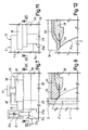
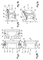
- Casing 13 facing lateral surface 11 ( Figure 3) mainly extends in a direction parallel to axis A of rotation of print cylinder 2, and has respective lateral walls 19, 20 at opposite ends. Casing 13 is wider than print cylinder 2, and lateral walls 19, 20 extend so as to partly face respective end surfaces 10 of the print cylinder. As shown schematically in Figure 4, lateral walls 19, 20 have respective plates 21, 22 hermetically engaging respective opposite end surfaces 10 of print cylinder 2 to prevent ink leakage. More specifically ( Figures 2 and 3), respective facing edges 21a, 22a of plates 21, 22 define flat-surface sealing members, and are designed to slide on respective end surfaces 10.
- edges 21a, 22a of plates 21, 22 rest on respective chords of end surfaces 10, slide on end surfaces 10 as print cylinder 2 rotates, and are made of antifriction material.
- lateral walls 19, 20 and plates 21, 22 may be Teflon-coated or chromium-plated internally and on edges 21a, 22a; or edges 21a, 22a may be in the form of inserts made of PTFE, chromium-plated steel, felt, or other low-friction material.
- the contact area between plates 21, 22 and respective end surfaces 10 of print cylinder 2 may optionally be lubricated, e.g. with water or solvent.
- Plates 21, 22 are slidable parallel to axis A and perpendicular to respective lateral walls 19, 20 and to end surfaces 10, and are pressed against end surfaces 10 by elastic contrast members 21b, 22b (i.e. elastic contrast members 21b, 22b push plates 21, 22 towards each other), so that the distance between edges 21a, 22a of plates 21, 22 can be adjusted to use unit 3 with print cylinders 2 of different sizes.
- unit 3 is movable back and forth, parallel to axis A of rotation, during operation of assembly 1, as explained later on, while still sealing the end surfaces of print cylinder 2.
- Doctor assembly 14 ( Figures 2 and 3) extends substantially the whole width of casing 13, is housed between and flush with lateral walls 19, 20, and comprises a doctor 24 fitted to a doctor carrier 25.
- Doctor 24 is a substantially rectangular blade preferably made of self-sharpening steel, and has a margin 24a resting on lateral surface 11, along a doctor line R coincident with a generating line of print cylinder 2.
- Doctor 24 is mounted to lie flat with respect to lateral surface 11 of print cylinder 2 in use, i.e. when unit 3 engages print cylinder 2. In other words, doctor 24 forms an acute angle with a plane tangent to lateral surface 11 along doctor line R, on the ink 12 feed side.
- Doctor carrier 25 is housed between lateral walls 19, 20, and is movable angularly, with respect to casing 13, about a regulating axis C parallel to axis A of rotation of print cylinder 2. More specifically, doctor carrier 25 comprises a rocking support 27; and a slide 28 integral with doctor 24 and which slides on a flat surface 27a of support 27. Slide 28 and support 27 are connected to each other by actuating members 30 which, in the example shown, comprise at least two screws fitted in axially-fixed manner to support 27, and the free ends of which are inserted inside respective threaded seats 31 formed in slide 28.
- slide 28 forms an adjusting mechanism by which to adjust the position of doctor 24 with respect to casing 13 (and therefore also with respect to lateral surface 11 of print cylinder 2), while support 27 acts as a doctor pressure adjusting mechanism.
- slide 28 and actuating members 30 provide for adjusting the position of doctor line R on lateral surface 11, and the parallelism of doctor 24 with respect to lateral surface 11.
- wear of doctor 24 may be taken up.
- the pressure exerted by doctor 24 on print cylinder 2 can be adjusted by acting on support 27, e.g. by means of a hydraulic or pneumatic actuator (not shown).
- Slide 28 has a sealing surface 28a adjacent to a sealing edge 13b of casing 13 and extending continuously along the whole width of and between the opposite ends of doctor assembly 14.
- Sealing edge 13b of casing 13 is fitted with a seal 32 (Figure 5), e.g. made of felt or elastomeric material, to prevent leakage of ink 12 through the clearance between sealing edge 13b and sealing surface 28a.
- a seal 32 Figure 5
- sealing between casing 13 and slide 28 may be achieved using a flexible blade 33, e.g. made of PTFE, fixed to casing 13, close to sealing edge 13b, and loaded to rest against sealing surface 28a of slide 28.
- seals 34, 35 are fitted at opposite ends of doctor 24 and doctor carrier 25, flush with lateral walls 19, 20 (see also Figures 7 and 8). More specifically, seals 34, 35, which are made for example of elastomeric material, are pressed against lateral walls 19, 20, project slightly from doctor 24, and slide on lateral surface 11 of print cylinder 2; and respective portions of seals 34, 35 also contact respective plates 21, 22. As shown in Figure 7, lateral walls 19, 20 have built-in PTFE pads 36 which are pressed against respective edges of doctor assembly 14 to prevent leakage of ink 12. More specifically, pads 36 are pressed by respective screws 37, with springs (not shown), inserted inside frames 38 fitted externally to lateral walls 19, 20. The pressure exerted on pads 36 is therefore adjustable.
- hood 17 is substantially cylindrical, and in use faces a portion of lateral surface 11 of print cylinder 2 extending (anticlockwise) between pressure roller 8 and inking chamber 15.
- hood 17 defines a wetting chamber 39 for limiting airing of the substantially ink-free portion of lateral surface 11.
- Wetting circuit 6 and cleaning circuit 7 communicate with the inside of hood 17 through respective inlets to feed the wetting fluid and cleaning fluid respectively onto lateral surface 11 of print cylinder 2 in controlled manner.
- Lateral surface 11 is thus kept damp and prevented from drying during normal operation of print assembly 1, while the cleaning fluid fed into hood 17 provides for fast, automatic cleaning of print cylinder 2 and the inside of hood 17.
- actuating assembly 4 comprises a frame 40; a carriage 41 connected to frame 40 by a support 42; and arms 43 fitted to carriage 41 and connected to unit 3 so that doctor assembly 14 is movable angularly with respect to regulating axis C.
- Frame 40 is movable angularly about axis A and rotates unit 3. More specifically, frame 40 is movable along a circular rail 45 fitted integrally to a frame (not shown) of print assembly 1 and coaxial with print cylinder 2.
- Frame 40 and rail 45 are connected to each other by a known rotary actuating member (not shown, and comprising, for example, a motor-driven gear fitted to frame 40 and meshing with a rack fitted to rail 45).
- Support 42 is fitted slidably to frame 40 by means of an adjusting screw 48 by which support 42 is movable in a direction substantially perpendicular to axis A.
- Support 42 also has guides 46 parallel to axis A and perpendicular to the slide direction of support 42.
- Carriage 41 is movable along guides 46, and in turn has guides 50 substantially perpendicular to axis A and to guides 46.
- Arms 43 (only one of which is shown in Figure 1) are integral with each other, and are fitted with pads which slide along guides 50; and unit 3 is mounted between the ends of arms 43, with doctor assembly 14 movable angularly about regulating axis C.
- actuating assembly 4 provides for rotating and translating unit 3 perpendicularly to axis A, so as to adjust the doctoring position and angle and so permit use of print cylinders 2 having different developments.
- the carriage 41 to frame 40 connection also allows unit 3 to move parallel to axis A: thus, alternating motion (back and forth), parallel to axis A, may be imparted to unit 3 to slide doctor 24 along doctor line R on lateral surface 11 and so clean doctor 24, even when assembly 1 is running.
- alternating motion (back and forth), parallel to axis A may be imparted to unit 3 to slide doctor 24 along doctor line R on lateral surface 11 and so clean doctor 24, even when assembly 1 is running.
- casing 13 is narrower than print cylinder 2 but wider than print portion 11a of lateral surface 11. More specifically, the width of casing 13 is such that lateral walls 19, 20 rest directly on respective lateral portions 11b of lateral surface 11, axially outwards of print portion 11a. As shown schematically in Figure 10, lateral walls 19, 20 hermetically engage lateral surface 11 to prevent ink leakage.
- edges 19a, 20a of lateral walls 19, 20 define radial sealing members on lateral surface 11, and are shaped to slide on lateral surface 11 at least along an arc extending between an inlet edge of casing 13 ( Figure 1) and margin 24a of doctor 24 (i.e. doctor line R).
- Edges 19a, 20a of lateral walls 19, 20 are made of antifriction material.
- lateral walls 19, 20 may be Teflon-coated or chromium-plated internally and on edges 19a, 20a; or, in this case too, edges 19a, 20a may be in the form of inserts made of PTFE, chromium-plated steel, felt, or other low-friction material.
- Lateral portions 11b of lateral surface 11 are preferably also chromium-plated or at any rate treated to reduce friction.
- FIG. 13 Further variations of the invention are shown in Figures 13 to 15.
- slide 28 supporting doctor 24 slides directly, without rocking, on a supporting portion 13c of casing 13, and unit 3 is connected to the actuating assembly 4 shown in Figure 1.
- slide 28 slides on supporting portion 13c of casing 13 in a sloping direction with respect to the plane of doctor 24, and cooperates with actuating members 30 and supporting portion 13c to adjust both the doctoring position and pressure.
- lateral walls 19, 20 of casing 13 rest on end surfaces 10 of print cylinder 2, whereas, in corresponding variations not shown, they rest on lateral surface 11.
- plates 21, 22 are hinged to respective lateral walls 19, 20, and are pressed against end surfaces 10 of print cylinder 2 by torsion springs 50; and edges 21a, 22a of plates 21, 22 are rounded to ensure sealing regardless of the tilt of plates 21, 22 with respect to end surfaces 10 (e.g. during back and forth movement).
- both the doctor position adjusting mechanism and the inking unit actuating assembly may be designed in various equivalent ways, but still in such a manner as to permit use of print cylinders of different developments, and control of the doctor position with respect to the print cylinder, and of doctoring angle and pressure. More specifically, mechanisms may be provided to translate and rotate the doctor and/or the entire inking unit in directions and about axes other than those described.
- the sealing system between the casing, doctor assembly, and print cylinder may also be other than as described; and all the embodiments described may be provided with hoods.
Landscapes
- Engineering & Computer Science (AREA)
- Mechanical Engineering (AREA)
- Inking, Control Or Cleaning Of Printing Machines (AREA)
- Screen Printers (AREA)
- Rotary Presses (AREA)
- Printing Plates And Materials Therefor (AREA)
- Photoreceptors In Electrophotography (AREA)
- Table Equipment (AREA)
Claims (20)
- Einfärb- und Rakeleinheit (3) für einen Rotationstiefdruck- und -auftragzylinder, umfassend ein Gehäuse (13); eine Rakelanordnung (14), die eine Rakel (24) umfasst, die an einem Rakelträger (25) angebracht ist; und eine Einfärbkammer (15), die durch eine konkave innere Oberfläche (13a) des Gehäuses (13) und mindestens teilweise durch die Rakelanordnung (14) begrenzt wird; wobei das Gehäuse (13) und die Rakelanordnung (14) einen Kastenkörper (18) bilden, der geschlossen ist, abgesehen von einer Seite, die im Gebrauch mit einem Druckzylinder (2) im Eingriff steht; dadurch gekennzeichnet, dass die Rakel (24) so montiert ist, dass sie in Bezug zu einer seitlichen Oberfläche (11) des Druckzylinders (2) flach liegt, wenn der Kastenkörper (18) mit dem Druckzylinder (2) im Eingriff steht; und dadurch, dass der Rakelträger (25) umfasst: eine schwenkbare Halterung (27), die sich um eine im Gebrauch zu einer Drehachse (A) des Druckzylinders (2) parallele Regulierachse (C) dreht; und einen Schieber (28), der mit der Rakel (24) als Einheit ausgebildet ist und der auf der Halterung (27) gleitet.
- Einheit nach Anspruch 1, gekennzeichnet durch Umfassen von ersten Dichteinrichtungen (21, 21a, 22, 22a; 19a, 20a) zur hermetischen Verbindung mit dem Druckzylinder (2).
- Einheit nach Anspruch 2, dadurch gekennzeichnet, dass die ersten Dichteinrichtungen (21, 21a, 22, 22a) Flachseiten-Dichteinrichtungen sind, die konstruiert sind, um mit entgegengesetzten Endoberflächen (10) des Druckzylinders (2) in Eingriff zu treten.
- Einheit nach Anspruch 3, dadurch gekennzeichnet, dass die ersten Dichteinrichtungen (21, 21a, 22, 22a) eine erste und eine zweite Platte (21, 22) umfassen, die an entgegengesetzten Enden des Gehäuses (13) angebracht sind und respektive Dichtränder (21a, 22a) aufweisen, die einander zugewandt sind und angeordnet sind, um auf respektiven besagten Endoberflächen (10) zu gleiten, wenn der Kastenkörper (18) mit dem Druckzylinder (2) in Eingriff steht.
- Einheit nach Anspruch 4, dadurch gekennzeichnet, dass die erste und zweite Platte (21, 22) in Bezug zum Gehäuse (13) bewegbar sind; und gekennzeichnet durch Umfassen von elastischen Einrichtungen (21b, 22b; 50), die mit der ersten und zweiten Platte (21, 22) verbunden sind, um die erste und zweite Platte (21, 22) gegen respektive besagte Endoberflächen (10) zu pressen, wenn der Kastenkörper (18) mit dem Druckzylinder (2) in Eingriff tritt.
- Einheit nach Anspruch 2, dadurch gekennzeichnet, dass die ersten Dichteinrichtungen (19a, 20a) radiale Dichteinrichtungen sind, die so geformt sind, dass sie mit der seitlichen Oberfläche (11) des Druckzylinders (2) in Eingriff treten.
- Einheit nach Anspruch 6, dadurch gekennzeichnet, dass die ersten Dichteinrichtungen (19a, 20a) an entgegengesetzten Enden der Rakelanordnung (14) durch das Gehäuse (13) getragen werden und Dichtränder (19a, 20a) des Gehäuses (13) umfassen, die geformt sind, um auf der seitlichen Oberfläche (11) des Druckzylinders (2) entlang mindestens einem vorbestimmten Bogen zu gleiten, wenn der Kastenkörper (18) mit dem Druckzylinder (2) in Eingriff steht.
- Einheit nach einem der vorangehenden Ansprüche, gekennzeichnet durch Umfassen von zweiten Dichteinrichtungen (34, 35, 36) zwischen der Rakelanordnung (14) und dem Gehäuse (13).
- Einheit nach Anspruch 8, dadurch gekennzeichnet, dass die zweiten Dichteinrichtungen (34, 35, 36) Dichtungen (34, 35) umfassen, die an entgegengesetzten Enden der Rakelanordnung (14) angeordnet sind, die mit einer ersten bzw. zweiten seitlichen Wand (19, 20) des Gehäuses (13) bündig sind.
- Einheit nach Anspruch 9, dadurch gekennzeichnet, dass die zweiten Dichteinrichtungen (34, 35, 36) umfassen: Auflagen (36), die aus friktionsarmem Material hergestellt sind, die in der ersten und zweiten seitlichen Wand (19, 20) des Gehäuses (13) aufgenommen sind und an entgegengesetzten Enden der Rakelanordnung (14) angeordnet sind; und Druckeinrichtungen (37, 38), um die Auflagen (36) gegen die entgegengesetzten Ende der Rakelanordnung (14) zu pressen.
- Einheit nach einem der vorangehenden Ansprüche, gekennzeichnet durch Umfassen von dritten Dichteinrichtungen (32, 33) zwischen einer Dichtoberfläche (28a) der Rakelanordnung (14), die sich kontinuierlich entlang der gesamten Breite der Rakelanordnung (14) erstreckt, und einem zur Dichtoberfläche (28a) benachbarten Rand (13b) des Gehäuses (13).
- Einheit nach einem der vorangehenden Ansprüche, dadurch gekennzeichnet, dass die Rakel (24) an dem Rakelträger (25) angebracht ist, um im Gebrauch auf der seitlichen Oberfläche (11) des Druckzylinders (2) entlang einer Rakellinie (R) zu liegen; wobei die Rakel (24) mit einer mit der seitlichen Oberfläche (11) des Druckzylinders (2) sich berührenden Ebene entlang der Rakellinie (R) auf der Farb (12)-Zufuhrseite einen spitzen Winkel bildet.
- Einheit nach einem der vorangehenden Ansprüche, gekennzeichnet durch Umfassen von Stellelementen (30), um den Schieber (28) in Bezug zur Halterung (27a; 13c) zu bewegen.
- Einheit nach einem der vorangehenden Ansprüche, gekennzeichnet durch Umfassen einer Einfärbwalze (16), die im Innern der Einfärbkammer (15) untergebracht ist, wobei sich eine Drehachse (B) parallel zur Drehachse (A) des Druckzylinders (2) befindet, um im Innern der Einfärbkammer (15) gesammelte Farbe (12) gegen die seitliche Oberfläche (11) des Druckzylinders (2) zu pressen.
- Einheit nach einem der vorangehenden Ansprüche, gekennzeichnet durch Umfassen einer Haube (17), die konstruiert ist, um im Gebrauch eine Befeuchtungskammer (39) um einen Teil der seitlichen Oberfläche (11) des Druckzylinders (2) zu begrenzen, der sich im Wesentlichen zwischen einem Druckbereich (8) und der Einfärbkammer (15) erstreckt.
- Einheit nach Anspruch 15, gekennzeichnet durch Umfassen von ersten und zweiten Zufuhreinrichtungen (6, 7) zur Zufuhr eines Befeuchtungsfluids bzw. eines Reinigungsfluids in die Haube (17).
- Rotationstiefdruck- und -auftraganordnung (1), umfassend einen Druckzylinder (2) mit einer Drehachse (A); gekennzeichnet durch Umfassen einer Einfärb- und Rakeleinheit (3) wie in einem der Ansprüche 1 bis 16 beansprucht.
- Anordnung nach Anspruch 17, gekennzeichnet durch Umfassen von Stelleinrichtungen (4) zur Einstellung der relativen Position der Einfärb- und Rakeleinheit (3) in Bezug zum Druckzylinder (2).
- Anordnung nach Anspruch 18, dadurch gekennzeichnet, dass die Stelleinrichtungen (4) Drehstelleinrichtungen (40, 45) umfassen, um die Einfärb- und Rakeleinheit (3) um die Drehachse (A) des Druckzylinders (2) zu drehen.
- Anordnung nach Anspruch 18 oder 19, dadurch gekennzeichnet, dass die Stelleinrichtungen (4) umfassen: erste Translationsstelleinrichtungen (41) zur Translation der Einfärb- und Rakeleinheit (3) in einer zur Drehachse (A) im Wesentlichen senkrechten ersten Richtung; und zweite Translationsstelleinrichtungen (4) zur Translation der Einfärb- und Rakeleinheit (3) in einer zur Drehachse (A) im Wesentlichen parallelen zweiten Richtung.
Applications Claiming Priority (2)
| Application Number | Priority Date | Filing Date | Title |
|---|---|---|---|
| IT001539A ITMI20031539A1 (it) | 2003-07-25 | 2003-07-25 | Unita' di inchiostrazione e raclatura per un gruppo di stampa e spalmatura rotocalcografica. |
| PCT/EP2004/051597 WO2005011981A1 (en) | 2003-07-25 | 2004-07-23 | Inking and doctor unit for a rotogravure print and spread assembly |
Publications (2)
| Publication Number | Publication Date |
|---|---|
| EP1648704A1 EP1648704A1 (de) | 2006-04-26 |
| EP1648704B1 true EP1648704B1 (de) | 2007-06-13 |
Family
ID=34113430
Family Applications (1)
| Application Number | Title | Priority Date | Filing Date |
|---|---|---|---|
| EP04766310A Expired - Lifetime EP1648704B1 (de) | 2003-07-25 | 2004-07-23 | Farbwerk und rakeleinheit für rotationstiefdruck und verteilanordnung |
Country Status (11)
| Country | Link |
|---|---|
| US (1) | US20070062387A1 (de) |
| EP (1) | EP1648704B1 (de) |
| JP (1) | JP2006528563A (de) |
| KR (1) | KR20060113642A (de) |
| CN (1) | CN1829606A (de) |
| AT (1) | ATE364505T1 (de) |
| BR (1) | BRPI0412602A (de) |
| DE (1) | DE602004007001T2 (de) |
| ES (1) | ES2287768T3 (de) |
| IT (1) | ITMI20031539A1 (de) |
| WO (1) | WO2005011981A1 (de) |
Families Citing this family (11)
| Publication number | Priority date | Publication date | Assignee | Title |
|---|---|---|---|---|
| DE102005055156B3 (de) * | 2005-11-18 | 2007-05-31 | OCé PRINTING SYSTEMS GMBH | Vorrichtung und Verfahren zur Entwicklung von auf einem Zwischenbildträger erzeugten Potentialbilder bei einer elektrografischen Druck- oder Kopiereinrichtung |
| US8915184B2 (en) * | 2007-04-27 | 2014-12-23 | Bobst Mex Sa | Doctor blade system for print unit intended for a photogravure printing machine |
| DK176867B1 (da) * | 2008-05-23 | 2010-02-01 | Tresu As | Drejelig kammerrakel |
| CN102627022A (zh) * | 2012-04-20 | 2012-08-08 | 河南鑫瑞达节能建材科技有限公司 | 一种装饰面板印刷机 |
| JP6233807B2 (ja) * | 2014-02-26 | 2017-11-22 | 株式会社小森コーポレーション | グラビア印刷機およびグラビア印刷機の運転方法 |
| CN104228315B (zh) * | 2014-09-25 | 2018-07-20 | 山东鲁烟莱州印务有限公司 | 一种凹印机油墨防溅、防印刷水印装置 |
| GB2582635B (en) * | 2019-03-28 | 2021-12-29 | Archipelago Tech Group Ltd | Device, method, and assembly for loading nozzles with fluid |
| CN112046128A (zh) * | 2019-06-05 | 2020-12-08 | 至善实业股份有限公司 | 凹版印刷机的同向封闭式刮刀装置 |
| CN114801463B (zh) * | 2022-06-06 | 2023-12-22 | 四川信立包装有限公司 | 一种用于包装印刷的智能化供墨装置及其应用方法 |
| CN117944362B (zh) * | 2024-03-06 | 2024-08-06 | 临沂江源装饰材料有限公司 | 一种凹版印刷用刮墨装置 |
| DE102024107229A1 (de) * | 2024-03-14 | 2025-09-18 | Rkw Se | Spritzschutzvorrichtung für Rollenrotationsdruckmaschinen |
Family Cites Families (17)
| Publication number | Priority date | Publication date | Assignee | Title |
|---|---|---|---|---|
| US2377110A (en) * | 1943-09-15 | 1945-05-29 | Rice Barton Corp | Printing roll inking device |
| GB604568A (en) * | 1944-11-27 | 1948-07-06 | Goss Printing Press Co Ltd | Improvements in or relating to ink fountains for use in printing presses |
| US4488483A (en) * | 1982-05-31 | 1984-12-18 | Kabushiki Kaisha Tokyo Kikai Seisakusho | Multicolor rotary printing press |
| US4590855A (en) * | 1984-06-18 | 1986-05-27 | Printco Industries, Ltd. | Reverse angle doctor blade assembly with stationary end seal |
| US4945832A (en) * | 1986-05-16 | 1990-08-07 | Odom Jimmie L | Doctor blade system |
| DE3737531A1 (de) * | 1987-11-05 | 1989-05-18 | Koenig & Bauer Ag | Farbauftragsleiste fuer ein spuelfarbwerk einer rotationsdruckmaschine |
| EP0368485A3 (de) * | 1988-10-31 | 1991-01-30 | Seiken Graphics, Inc. | Lithographisches Drucken |
| US4901641A (en) * | 1988-11-30 | 1990-02-20 | Bobst Sa | Printing press |
| DE4138807C1 (en) * | 1991-11-26 | 1993-06-03 | Cornelis Wapenveld Nl Gorter | Colour chamber doctor - is for colour-transfer, screened circular cylindrical body such as screen roller or engraved cylinder |
| US5410961A (en) * | 1992-12-30 | 1995-05-02 | Fit Group, Inc. | Fountain assembly |
| DE4340128C2 (de) * | 1993-11-25 | 1996-07-25 | Koenig & Bauer Albert Ag | Tiefdruckfarbwerk |
| DE4425478A1 (de) * | 1994-07-19 | 1996-02-08 | Roland Man Druckmasch | Kammerrakel |
| DE29602257U1 (de) * | 1996-02-09 | 1996-03-28 | MAN Roland Druckmaschinen AG, 63075 Offenbach | Kammerrakel |
| JPH10235839A (ja) * | 1997-02-24 | 1998-09-08 | Toppan Printing Co Ltd | グラビア印刷機のインキング装置 |
| WO1998050233A1 (de) * | 1997-05-05 | 1998-11-12 | Koenig & Bauer Aktiengesellschaft | Farbwerk zum einfärben eines formzylinders einer tiefdruckmaschine |
| EP0941845A1 (de) * | 1998-03-07 | 1999-09-15 | Fischer & Krecke Gmbh & Co. | Dichtungsanordnung für Kammerrakel |
| JPH11268247A (ja) * | 1998-03-24 | 1999-10-05 | Dainippon Printing Co Ltd | インキ供給装置及びチャンバ装置 |
-
2003
- 2003-07-25 IT IT001539A patent/ITMI20031539A1/it unknown
-
2004
- 2004-07-23 KR KR1020067001615A patent/KR20060113642A/ko not_active Withdrawn
- 2004-07-23 ES ES04766310T patent/ES2287768T3/es not_active Expired - Lifetime
- 2004-07-23 CN CNA2004800215046A patent/CN1829606A/zh active Pending
- 2004-07-23 AT AT04766310T patent/ATE364505T1/de not_active IP Right Cessation
- 2004-07-23 BR BRPI0412602-5A patent/BRPI0412602A/pt not_active IP Right Cessation
- 2004-07-23 WO PCT/EP2004/051597 patent/WO2005011981A1/en not_active Ceased
- 2004-07-23 US US10/565,888 patent/US20070062387A1/en not_active Abandoned
- 2004-07-23 DE DE602004007001T patent/DE602004007001T2/de not_active Expired - Lifetime
- 2004-07-23 EP EP04766310A patent/EP1648704B1/de not_active Expired - Lifetime
- 2004-07-23 JP JP2006520840A patent/JP2006528563A/ja active Pending
Non-Patent Citations (1)
| Title |
|---|
| None * |
Also Published As
| Publication number | Publication date |
|---|---|
| ITMI20031539A1 (it) | 2003-10-24 |
| DE602004007001T2 (de) | 2008-02-14 |
| CN1829606A (zh) | 2006-09-06 |
| US20070062387A1 (en) | 2007-03-22 |
| JP2006528563A (ja) | 2006-12-21 |
| WO2005011981A1 (en) | 2005-02-10 |
| KR20060113642A (ko) | 2006-11-02 |
| ATE364505T1 (de) | 2007-07-15 |
| ES2287768T3 (es) | 2007-12-16 |
| BRPI0412602A (pt) | 2006-09-19 |
| EP1648704A1 (de) | 2006-04-26 |
| DE602004007001D1 (de) | 2007-07-26 |
Similar Documents
| Publication | Publication Date | Title |
|---|---|---|
| US4066014A (en) | Pressurized ink applicator for intaglio printing press | |
| US5054392A (en) | Lithographic printing press having an ink duct with a divided chamber | |
| CA1215826A (en) | Reverse angle doctor blade assembly with stationary end seal | |
| US4497250A (en) | Ink Fountain | |
| US3585932A (en) | Automatic inking system for rotary newspaper printing press | |
| US5103732A (en) | Doctor blade head assembly and printing apparatus therewith | |
| JP3184050B2 (ja) | グラビア印刷機のインク供給装置 | |
| US20070062387A1 (en) | Inking and doctor unit for a rotogravure print and spread assembly | |
| CN201092142Y (zh) | 柔性版印刷封闭刮刀装置 | |
| US4432282A (en) | Printing press | |
| US5010815A (en) | Doctor device | |
| US5355799A (en) | Applicator device for viscous materials | |
| US20090035037A1 (en) | Doctor blade chamber for high viscous ink | |
| US5031529A (en) | Inking system for lithographic printing | |
| EP0461426B1 (de) | System zum Zuführen von Druckflüssigkeit unter Druck zum lithographischen Drucken ohne Farbmesser | |
| CN111093998B (zh) | 具有最小储墨量的输墨系统 | |
| GB2327196A (en) | Device for varnishing printed materials in an offset printing unit | |
| EP0047618B1 (de) | Tiefdruckpresse | |
| EP0294022A1 (de) | ||
| US6119595A (en) | Gravure printing press with encapsulated ink applicator and method | |
| EP0476328B1 (de) | Verbessertes Drucksystem ohne Farbmesser zum lithographischem Drucken ohne Farbmesser | |
| US8007090B2 (en) | Ink-supply cartridge for printer roll | |
| JPH07214757A (ja) | 回転円柱体に形成された凹みへの液体の充填方法および装置 | |
| US2579181A (en) | Enclosed gravure fountain | |
| CN111448074A (zh) | 具有带储存容器的装置的加工机械以及用于运行储存容器的方法 |
Legal Events
| Date | Code | Title | Description |
|---|---|---|---|
| PUAI | Public reference made under article 153(3) epc to a published international application that has entered the european phase |
Free format text: ORIGINAL CODE: 0009012 |
|
| 17P | Request for examination filed |
Effective date: 20060131 |
|
| AK | Designated contracting states |
Kind code of ref document: A1 Designated state(s): AT BE BG CH CY CZ DE DK EE ES FI FR GB GR HU IE IT LI LU MC NL PL PT RO SE SI SK TR |
|
| 17Q | First examination report despatched |
Effective date: 20060619 |
|
| DAX | Request for extension of the european patent (deleted) | ||
| GRAP | Despatch of communication of intention to grant a patent |
Free format text: ORIGINAL CODE: EPIDOSNIGR1 |
|
| GRAS | Grant fee paid |
Free format text: ORIGINAL CODE: EPIDOSNIGR3 |
|
| GRAA | (expected) grant |
Free format text: ORIGINAL CODE: 0009210 |
|
| AK | Designated contracting states |
Kind code of ref document: B1 Designated state(s): AT BE BG CH CY CZ DE DK EE ES FI FR GB GR HU IE IT LI LU MC NL PL PT RO SE SI SK TR |
|
| REG | Reference to a national code |
Ref country code: GB Ref legal event code: FG4D |
|
| REG | Reference to a national code |
Ref country code: CH Ref legal event code: EP |
|
| REG | Reference to a national code |
Ref country code: IE Ref legal event code: FG4D |
|
| REF | Corresponds to: |
Ref document number: 602004007001 Country of ref document: DE Date of ref document: 20070726 Kind code of ref document: P |
|
| PG25 | Lapsed in a contracting state [announced via postgrant information from national office to epo] |
Ref country code: SE Free format text: LAPSE BECAUSE OF FAILURE TO SUBMIT A TRANSLATION OF THE DESCRIPTION OR TO PAY THE FEE WITHIN THE PRESCRIBED TIME-LIMIT Effective date: 20070913 |
|
| REG | Reference to a national code |
Ref country code: CH Ref legal event code: NV Representative=s name: ANDRE ROLAND CONSEILS EN PROPRIETE INTELLECTUELLE |
|
| ET | Fr: translation filed | ||
| PG25 | Lapsed in a contracting state [announced via postgrant information from national office to epo] |
Ref country code: PL Free format text: LAPSE BECAUSE OF FAILURE TO SUBMIT A TRANSLATION OF THE DESCRIPTION OR TO PAY THE FEE WITHIN THE PRESCRIBED TIME-LIMIT Effective date: 20070613 Ref country code: AT Free format text: LAPSE BECAUSE OF FAILURE TO SUBMIT A TRANSLATION OF THE DESCRIPTION OR TO PAY THE FEE WITHIN THE PRESCRIBED TIME-LIMIT Effective date: 20070613 |
|
| NLV1 | Nl: lapsed or annulled due to failure to fulfill the requirements of art. 29p and 29m of the patents act | ||
| REG | Reference to a national code |
Ref country code: ES Ref legal event code: FG2A Ref document number: 2287768 Country of ref document: ES Kind code of ref document: T3 |
|
| PG25 | Lapsed in a contracting state [announced via postgrant information from national office to epo] |
Ref country code: BE Free format text: LAPSE BECAUSE OF FAILURE TO SUBMIT A TRANSLATION OF THE DESCRIPTION OR TO PAY THE FEE WITHIN THE PRESCRIBED TIME-LIMIT Effective date: 20070613 |
|
| PG25 | Lapsed in a contracting state [announced via postgrant information from national office to epo] |
Ref country code: PT Free format text: LAPSE BECAUSE OF FAILURE TO SUBMIT A TRANSLATION OF THE DESCRIPTION OR TO PAY THE FEE WITHIN THE PRESCRIBED TIME-LIMIT Effective date: 20071113 Ref country code: NL Free format text: LAPSE BECAUSE OF FAILURE TO SUBMIT A TRANSLATION OF THE DESCRIPTION OR TO PAY THE FEE WITHIN THE PRESCRIBED TIME-LIMIT Effective date: 20070613 Ref country code: SI Free format text: LAPSE BECAUSE OF FAILURE TO SUBMIT A TRANSLATION OF THE DESCRIPTION OR TO PAY THE FEE WITHIN THE PRESCRIBED TIME-LIMIT Effective date: 20070613 Ref country code: BG Free format text: LAPSE BECAUSE OF FAILURE TO SUBMIT A TRANSLATION OF THE DESCRIPTION OR TO PAY THE FEE WITHIN THE PRESCRIBED TIME-LIMIT Effective date: 20070913 Ref country code: CZ Free format text: LAPSE BECAUSE OF FAILURE TO SUBMIT A TRANSLATION OF THE DESCRIPTION OR TO PAY THE FEE WITHIN THE PRESCRIBED TIME-LIMIT Effective date: 20070613 |
|
| PG25 | Lapsed in a contracting state [announced via postgrant information from national office to epo] |
Ref country code: SK Free format text: LAPSE BECAUSE OF FAILURE TO SUBMIT A TRANSLATION OF THE DESCRIPTION OR TO PAY THE FEE WITHIN THE PRESCRIBED TIME-LIMIT Effective date: 20070613 |
|
| PLBE | No opposition filed within time limit |
Free format text: ORIGINAL CODE: 0009261 |
|
| STAA | Information on the status of an ep patent application or granted ep patent |
Free format text: STATUS: NO OPPOSITION FILED WITHIN TIME LIMIT |
|
| PG25 | Lapsed in a contracting state [announced via postgrant information from national office to epo] |
Ref country code: DK Free format text: LAPSE BECAUSE OF FAILURE TO SUBMIT A TRANSLATION OF THE DESCRIPTION OR TO PAY THE FEE WITHIN THE PRESCRIBED TIME-LIMIT Effective date: 20070613 Ref country code: GR Free format text: LAPSE BECAUSE OF FAILURE TO SUBMIT A TRANSLATION OF THE DESCRIPTION OR TO PAY THE FEE WITHIN THE PRESCRIBED TIME-LIMIT Effective date: 20070914 Ref country code: MC Free format text: LAPSE BECAUSE OF NON-PAYMENT OF DUE FEES Effective date: 20070731 |
|
| 26N | No opposition filed |
Effective date: 20080314 |
|
| PG25 | Lapsed in a contracting state [announced via postgrant information from national office to epo] |
Ref country code: RO Free format text: LAPSE BECAUSE OF FAILURE TO SUBMIT A TRANSLATION OF THE DESCRIPTION OR TO PAY THE FEE WITHIN THE PRESCRIBED TIME-LIMIT Effective date: 20070613 |
|
| PG25 | Lapsed in a contracting state [announced via postgrant information from national office to epo] |
Ref country code: IE Free format text: LAPSE BECAUSE OF NON-PAYMENT OF DUE FEES Effective date: 20070723 |
|
| PG25 | Lapsed in a contracting state [announced via postgrant information from national office to epo] |
Ref country code: EE Free format text: LAPSE BECAUSE OF FAILURE TO SUBMIT A TRANSLATION OF THE DESCRIPTION OR TO PAY THE FEE WITHIN THE PRESCRIBED TIME-LIMIT Effective date: 20070613 |
|
| PG25 | Lapsed in a contracting state [announced via postgrant information from national office to epo] |
Ref country code: FI Free format text: LAPSE BECAUSE OF FAILURE TO SUBMIT A TRANSLATION OF THE DESCRIPTION OR TO PAY THE FEE WITHIN THE PRESCRIBED TIME-LIMIT Effective date: 20070613 |
|
| PG25 | Lapsed in a contracting state [announced via postgrant information from national office to epo] |
Ref country code: CY Free format text: LAPSE BECAUSE OF FAILURE TO SUBMIT A TRANSLATION OF THE DESCRIPTION OR TO PAY THE FEE WITHIN THE PRESCRIBED TIME-LIMIT Effective date: 20070613 |
|
| PG25 | Lapsed in a contracting state [announced via postgrant information from national office to epo] |
Ref country code: LU Free format text: LAPSE BECAUSE OF NON-PAYMENT OF DUE FEES Effective date: 20070723 |
|
| PG25 | Lapsed in a contracting state [announced via postgrant information from national office to epo] |
Ref country code: HU Free format text: LAPSE BECAUSE OF FAILURE TO SUBMIT A TRANSLATION OF THE DESCRIPTION OR TO PAY THE FEE WITHIN THE PRESCRIBED TIME-LIMIT Effective date: 20071214 |
|
| PGFP | Annual fee paid to national office [announced via postgrant information from national office to epo] |
Ref country code: CH Payment date: 20110725 Year of fee payment: 8 Ref country code: FR Payment date: 20110729 Year of fee payment: 8 |
|
| PGFP | Annual fee paid to national office [announced via postgrant information from national office to epo] |
Ref country code: GB Payment date: 20110718 Year of fee payment: 8 Ref country code: TR Payment date: 20110711 Year of fee payment: 8 Ref country code: DE Payment date: 20110728 Year of fee payment: 8 Ref country code: ES Payment date: 20110718 Year of fee payment: 8 |
|
| PGFP | Annual fee paid to national office [announced via postgrant information from national office to epo] |
Ref country code: IT Payment date: 20110725 Year of fee payment: 8 |
|
| REG | Reference to a national code |
Ref country code: CH Ref legal event code: PCAR Free format text: ANDRE ROLAND S.A.;CASE POSTALE 5107;1002 LAUSANNE (CH) |
|
| REG | Reference to a national code |
Ref country code: CH Ref legal event code: PL |
|
| GBPC | Gb: european patent ceased through non-payment of renewal fee |
Effective date: 20120723 |
|
| REG | Reference to a national code |
Ref country code: FR Ref legal event code: ST Effective date: 20130329 |
|
| PG25 | Lapsed in a contracting state [announced via postgrant information from national office to epo] |
Ref country code: FR Free format text: LAPSE BECAUSE OF NON-PAYMENT OF DUE FEES Effective date: 20120731 Ref country code: CH Free format text: LAPSE BECAUSE OF NON-PAYMENT OF DUE FEES Effective date: 20120731 Ref country code: GB Free format text: LAPSE BECAUSE OF NON-PAYMENT OF DUE FEES Effective date: 20120723 Ref country code: DE Free format text: LAPSE BECAUSE OF NON-PAYMENT OF DUE FEES Effective date: 20130201 Ref country code: LI Free format text: LAPSE BECAUSE OF NON-PAYMENT OF DUE FEES Effective date: 20120731 |
|
| REG | Reference to a national code |
Ref country code: DE Ref legal event code: R119 Ref document number: 602004007001 Country of ref document: DE Effective date: 20130201 |
|
| PG25 | Lapsed in a contracting state [announced via postgrant information from national office to epo] |
Ref country code: IT Free format text: LAPSE BECAUSE OF NON-PAYMENT OF DUE FEES Effective date: 20120723 |
|
| REG | Reference to a national code |
Ref country code: ES Ref legal event code: FD2A Effective date: 20131021 |
|
| PG25 | Lapsed in a contracting state [announced via postgrant information from national office to epo] |
Ref country code: ES Free format text: LAPSE BECAUSE OF NON-PAYMENT OF DUE FEES Effective date: 20120724 |
|
| PG25 | Lapsed in a contracting state [announced via postgrant information from national office to epo] |
Ref country code: TR Free format text: LAPSE BECAUSE OF NON-PAYMENT OF DUE FEES Effective date: 20120723 |