EP1649162B1 - Mit einem elektromagnetischen dämpfungsmittel versehene wellenenergieanordnung - Google Patents
Mit einem elektromagnetischen dämpfungsmittel versehene wellenenergieanordnung Download PDFInfo
- Publication number
- EP1649162B1 EP1649162B1 EP04727172A EP04727172A EP1649162B1 EP 1649162 B1 EP1649162 B1 EP 1649162B1 EP 04727172 A EP04727172 A EP 04727172A EP 04727172 A EP04727172 A EP 04727172A EP 1649162 B1 EP1649162 B1 EP 1649162B1
- Authority
- EP
- European Patent Office
- Prior art keywords
- winding
- stator
- wave power
- rotor
- power assembly
- Prior art date
- Legal status (The legal status is an assumption and is not a legal conclusion. Google has not performed a legal analysis and makes no representation as to the accuracy of the status listed.)
- Expired - Lifetime
Links
Images

Classifications
-
- F—MECHANICAL ENGINEERING; LIGHTING; HEATING; WEAPONS; BLASTING
- F03—MACHINES OR ENGINES FOR LIQUIDS; WIND, SPRING, OR WEIGHT MOTORS; PRODUCING MECHANICAL POWER OR A REACTIVE PROPULSIVE THRUST, NOT OTHERWISE PROVIDED FOR
- F03B—MACHINES OR ENGINES FOR LIQUIDS
- F03B13/00—Adaptations of machines or engines for special use; Combinations of machines or engines with driving or driven apparatus; Power stations or aggregates
- F03B13/12—Adaptations of machines or engines for special use; Combinations of machines or engines with driving or driven apparatus; Power stations or aggregates characterised by using wave or tide energy
- F03B13/14—Adaptations of machines or engines for special use; Combinations of machines or engines with driving or driven apparatus; Power stations or aggregates characterised by using wave or tide energy using wave energy
- F03B13/16—Adaptations of machines or engines for special use; Combinations of machines or engines with driving or driven apparatus; Power stations or aggregates characterised by using wave or tide energy using wave energy using the relative movement between a wave-operated member, i.e. a "wom" and another member, i.e. a reaction member or "rem"
- F03B13/18—Adaptations of machines or engines for special use; Combinations of machines or engines with driving or driven apparatus; Power stations or aggregates characterised by using wave or tide energy using wave energy using the relative movement between a wave-operated member, i.e. a "wom" and another member, i.e. a reaction member or "rem" where the other member, i.e. rem is fixed, at least at one point, with respect to the sea bed or shore
-
- F—MECHANICAL ENGINEERING; LIGHTING; HEATING; WEAPONS; BLASTING
- F03—MACHINES OR ENGINES FOR LIQUIDS; WIND, SPRING, OR WEIGHT MOTORS; PRODUCING MECHANICAL POWER OR A REACTIVE PROPULSIVE THRUST, NOT OTHERWISE PROVIDED FOR
- F03B—MACHINES OR ENGINES FOR LIQUIDS
- F03B13/00—Adaptations of machines or engines for special use; Combinations of machines or engines with driving or driven apparatus; Power stations or aggregates
- F03B13/12—Adaptations of machines or engines for special use; Combinations of machines or engines with driving or driven apparatus; Power stations or aggregates characterised by using wave or tide energy
- F03B13/14—Adaptations of machines or engines for special use; Combinations of machines or engines with driving or driven apparatus; Power stations or aggregates characterised by using wave or tide energy using wave energy
-
- F—MECHANICAL ENGINEERING; LIGHTING; HEATING; WEAPONS; BLASTING
- F05—INDEXING SCHEMES RELATING TO ENGINES OR PUMPS IN VARIOUS SUBCLASSES OF CLASSES F01-F04
- F05B—INDEXING SCHEME RELATING TO WIND, SPRING, WEIGHT, INERTIA OR LIKE MOTORS, TO MACHINES OR ENGINES FOR LIQUIDS COVERED BY SUBCLASSES F03B, F03D AND F03G
- F05B2220/00—Application
- F05B2220/70—Application in combination with
- F05B2220/706—Application in combination with an electrical generator
- F05B2220/707—Application in combination with an electrical generator of the linear type
-
- Y—GENERAL TAGGING OF NEW TECHNOLOGICAL DEVELOPMENTS; GENERAL TAGGING OF CROSS-SECTIONAL TECHNOLOGIES SPANNING OVER SEVERAL SECTIONS OF THE IPC; TECHNICAL SUBJECTS COVERED BY FORMER USPC CROSS-REFERENCE ART COLLECTIONS [XRACs] AND DIGESTS
- Y02—TECHNOLOGIES OR APPLICATIONS FOR MITIGATION OR ADAPTATION AGAINST CLIMATE CHANGE
- Y02E—REDUCTION OF GREENHOUSE GAS [GHG] EMISSIONS, RELATED TO ENERGY GENERATION, TRANSMISSION OR DISTRIBUTION
- Y02E10/00—Energy generation through renewable energy sources
- Y02E10/30—Energy from the sea, e.g. using wave energy or salinity gradient
Definitions
- the present invention rebates in a first aspect to a wave power assembly, comprising a hull and a linear electric generator, the rotor of which by means of connection means is connected to the hull and the stator of which is arranged to be anchored at a sea/lake bottom.
- the invention in a second aspect, relates to a wave power plant comprising a plurality of wave power assemblies according to the invention.
- the invention relates to the use of the invented wave power assembly in order to produce electric current.
- the invention relates to a method for the generation of electric energy.
- the term rotor is used for the movable part of the linear generator.
- the term rotor does not relate to a rotary body but a linearly reciprocating body.
- the direction of motion of the rotor reference is made to the linear direction of motion thereof.
- the wave power assembly according to the invention is primarily intended for but not limited to applications up to 500 kW.
- stator is arranged for anchorage at the bottom of the sea does not necessarily imply that it is situated on the same. Neither that it has to be stiffly connected to the bottom of the sea.
- stator construction may naturally be floatingly supported and the anchorage may only consist of a line or the like, which prevents the assembly to drive away.
- Wave motions in the sea and large lakes are a potential energy source which till now is very little utilized.
- the available wave energy depends on the wave height and is naturally different for different locations.
- the average wave energy during a year is dependent on the different wind conditions, which are highly influenced by the distance of the location from the nearest coast. Measurements have, among other things, been made in the North Sea. At a measuring point approx. 100 km to the west of the coast of Jutland where the depth was approx. 50 m, measurings of the wave height have been made.
- a linear generator may be made very robust and simple and by it being anchored at the bottom, it becomes solidly unaffectabte by streams in the water.
- the only movable part of the generator will be the reciprocating rotor. By the few movable parts thereof and the simple constructive build-up thereof, the assembly becomes very reliable.
- a wave power assembly is previously known, which is based on the linear generator principle.
- the specification describes a generator anchored at the bottom, which generator produces electric energy from the wave motions of the sea surface.
- a generator coil is connected to a hull so that the coil moves up and down with the wave motions.
- a magnetic field acts on the coil when it moves so that an electromagnetic force is generated in the same.
- the magnetic field is such that it provides a uniform field having a single magnetic orientation along the length of stroke of the entire coil.
- the generator comprises a base plate on the bottom of the sea that carries the magnetic core in which the coil moves.
- a wave power assembly provided with a linear electric generator is previously known by US 4 539 485 .
- the rotor thereof consists of a number of permanent magnets and the winding of the generator is arranged in the surrounding stator.
- a wave power assembly having a linear generator in which the rotor is permanent magnetic and the stator comprises winding forming a plurality of poles distributed in the direction of motion of the rotor.
- a spring means is arranged in the form of a tension spring and exerts a downwardly directed tensile force on the rotor, i.e. directed against the lifting force of the hull.
- WO 0106119 discloses a wave power assembly provided with electromagnetic clamping of the motion of the generator.
- the rotor is subjected to axial forces. Said forces are pulsating and thereby lead to an uneven running and create disturbances.
- the object of the present invention is to reduce the same disturbances.
- a wave power assembly of the kind defined in the preamble of claim 1 comprising the special features that the generator is provided with an electromechanic damping means in order to keep the pulsations or the axial force exerted by the stator on the rotor on a relatively low level, which damping means comprises geometrical arrangement adapted herefor of at least some one of the stator winding, the stator slots and the rotor magnets.
- the invention is based on an analysis of the causes for the mentioned disturbances. This has led up to the understanding that the causes to a significant part can be derived to the electromagnetic transformation of energy and the courses of the axial magnetic forces that the stator in that connection exerts on the rotor. As a consequence off the magnets on the rotor passing past the windings of the stator, said forces will pulsate depending on the position of the respective magnetic pole in relation to a stator slot.
- This insight constitutes the basis for the measures that, according to the invention, are taken in order to overcome the disturbances.
- the generator is provided with means for keeping said pulsations at a relatively low level, the total axial force on the rotor will become much more even than otherwise, which results in more even and more undisturbed running.
- the means for this is related to the geometry of the components vital for the electromechanic transformation of energy.
- geometrically arranging the stator winding, the stator slots and the rotor magnets so that pulsating axial force occurring on the respective rotor magnet co-operates contra-cyclically with each other and is levelled out over time it is attained that the resulting magnetic axial force on the rotor becomes more even during the course of motion, the desired reduction of the disturbances being obtained.
- damping means should not be understood so that the means has the direct function of damping already developed pulsations but rather to prevent that the pulsations become so large as they would be in conventional arrangements of winding, slots and magnets.
- the stator comprises multiphase winding
- the electromagnetic damping means consists of the stator winding comprising fractional slot winding.
- Fractional slot winding is a well-tried construction for rotary electric generators and constitutes a simple and expedient way to, by means of the winding geometry, reduce the axial force pulsations.
- the fractional slot winding has a winding factor that is ⁇ 1.
- the advantage of such an embodiment is that it facilitates having less distance between the poles.
- the fractional slot winding has a winding factor that is >1. This is especially favourable in slow-running machines, which is normally the case in assemblies of the type to which the invention relates.
- the stator is composed of a plurality of stator packs distributed evenly around the rotor, with each stator pack having a winding that comprises fractional slot winding.
- the electromagnetic damping means comprises that at least some of the poles of the rotor and/or some of the winding slots of the stator are oriented obliquely in relation to a plane perpendicular to the direction of motion of the rotor.
- poles and/or winding slots being obliquely oriented, it is attained that a pole passes a winding gradually. Thereby, the magnetic force will correspondingly get a gradually increasing and decreasing strength with a less strong pulsation as a consequence.
- each pole comprises a magnet of an elongate shape having a longitudinal axis that forms an angle to a plane perpendicular to the direction of motion of the rotor.
- each pole comprises a group of a plurality of magnets, which are axially displaced in relation to each other.
- the winding slots form an angle to a plane perpendicular to the direction of motion of the rotor.
- the rotor can be formed in a conventional way.
- the embodiments above may naturally be combined so that the generator has an asymmetric alignment of the magnets, as well as the winding slots, if so at different inclinations. It may also be combined with fractional slot winding.
- the rotor is permanent magnetic, which constitutes a simple and expedient embodiment.
- the object set-up has been attained by a wave power plant comprising a plurality of wave power assemblies according to the invention, by the use of a wave power plant according to the invention in order to produce electric current, and by a method for production of electric current being carried out by means of a wave power assembly according to the invention, respectively, which are defined in claims 12, 13 and 14, respectively.
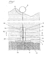
- Fig. 1 illustrates the principle of a wave power assembly according to the invention.
- a hull 3 is arranged to float on the sea surface 2. Waves impart reciprocating vertical motion to the hull 3.
- a linear generator 5 is anchored via a base plate 8 fastened at the bottom, which plate may be a concrete slab.
- the stator 6a, 6c of the linear generator is fastened.
- the stator consists of four vertical column-like stator packs, only two of which are visible in the figure.
- the rotor 7 of the generator is arranged. The same is connected to the hull 3 by means of a line 4.
- the rotor 7 is of permanent magnetic material.
- the base plate 8 has a centrally arranged hole 10, and concentrically therewith a bottom hole 9 is recessed in the bottom of the sea.
- the bottom hole 9 may suitably be lined.
- a tension spring 11 is fastened, which with the other end thereof is fastened at the lower end of the rotor 7.
- the hole 10 in the base plate 8 and the bottom hole 9 have a diameter allowing the rotor 7 to move freely through the same.
- Each stator pack 6a, 6c is composed of a number of modules. In the example shown, it is marked on the stator pack 6a how the same is divided into three vertically distributed modules 61, 62, 63.
- the spring may also be formed so that it in certain situations also can exert an upwardly directed force.
- the spring constant of the spring may be adjusted so that resonance is attained during as large a part of the time as possible.
- stator In order to be able to resist salt water, the stator is entirely or partly impregnated by VP or silicone.
- Figure 2 is a section along the line II-II in fig. 1 .
- the rotor 7 has a square cross-section and a stator pack 6a-6d is arranged at each side of the rotor 7.
- the winding of the respective stator pack is indicated by 12a-12d.
- the orientation of the sheet-metal plates in each stator pack is also seen.
- the air gap between the rotor and adjacent stator packs is in the order of some mm.
- Each stator pack comprises fractional slot winding, i.e. the winding factor is not an integer.
- Fractional slot winding is a generally known embodiment as regards rotary electric machines.
- Each slot 12 contains 4 turns of a winding and the different phases are indicated by different symbols.
- q is an integer.
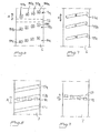
- figure 3 represents prior art.
- Fig. 4 shows, in a corresponding section, an embodiment example according to the invention. Also here, it is a matter of 3-phase, indicated correspondingly as in fig. 3 .
- the winding 13 has a winding factor that is greater than 1, a so-called pitch extension.
- Fig. 5 shows correspondingly an embodiment example at 3-phase with the winding factor of the winding 13 being smaller than 1, a so-called pitch reduction.
- Fig. 6 is a part of a side view of one the sides of a square rotor 7 according to an embodiment example of the invention.
- the direction of motion of the rotor is indicated by the arrow A.
- Each pole 14a, 14b, 14c consists of as plurality of permanent magnets 141a-144a.
- the magnets 141a-144a of a pole is somewhat displaced in the axial direction in relation to each other on a line forming a small angle to a plane perpendicular to the direction of motion A of the rotor.
- the magnets in the figure are on a straight line, but it may alternatively have another curve shape.
- the lowermost magnet 141 a of the pole 14a is situated at a certain distance from the uppermost magnet 144d in the half-pole 14b being closest below. Suitably, said distance corresponds to a half half-pole pitch or less.
- the surface of the rotor 7 shown in the figure co-operates with a stator pack located above the plane of the figure and having winding slots facing the rotor 7.
- One of the winding slots 13 of the stator pack is indicated by dashed lines in the figure.
- the axial force on the rotor 7 will, in that connection, be distributed in time in comparison with if the magnets 141 a-144a of the pole 14a had been oriented in a conventional way, parallel to the winding slot 13. Thereby, the axial force becomes less strongly pulsating.
- Fig. 7 is a view corresponding to the one in fig. 6 of an alternative embodiment example.
- each pole 14a-14c consists of a single magnet that is elongate and runs obliquely, correspondingly to the line connecting the magnets of the respective pole in fig. 6 .
- Fig. 8 is a part of a side view of a stator pack 6, and shows the side that is intended to be directed against the rotor.
- the winding slots 13a-13c of the stator pack 6 form a small angle to a plane perpendicular to the direction of motion A of the rotor.
- the rotor located above the plane of the figure, with one of the poles thereof having been indicated by dashed lines, will thereby gradually pass a stator slot 13b.
- a corresponding course of events is obtained as the one that is described in connection with fig. 6 .
- Fig. 9 is a view corresponding to the one in fig. 9 and illustrates an example with the winding slots 13 as well as the poles 14 being inclined, but in different directions and at smaller inclination than in the other examples.
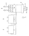
- a wave power plant according to the invention consists of two or more assemblies of the above-described kind. In fig. 10 , it is illustrated how these are connected in order to deliver energy to a mains.
- the power plant consists of three assemblies symbolically indicated by 20a-20c. Each assembly is, via a breaker or contactor 21 and a rectifier 22, connected to an inverter 23, in a bipolar circuit according to the figure. In the figure, a circuit diagram is drawn only for the assembly 20a. It should be appreciated that the other assemblies 20b, 20c are correspondingly connected.
- the inverter 23 delivers three-phase current to the mains 25, possibly via a transformer 24 and/or a filter.
- the rectifiers may be diodes that may be gate-controlled and of the type IGBT, GTO or tyristor, comprise gate-controlled bipolar components or be uncontrolled.
- the voltages on the DC side may be connected in parallel, connected in series or a combination of both.
Landscapes
- Engineering & Computer Science (AREA)
- Chemical & Material Sciences (AREA)
- Combustion & Propulsion (AREA)
- Mechanical Engineering (AREA)
- General Engineering & Computer Science (AREA)
- Other Liquid Machine Or Engine Such As Wave Power Use (AREA)
- Vibration Prevention Devices (AREA)
- Control Of Eletrric Generators (AREA)
- General Electrical Machinery Utilizing Piezoelectricity, Electrostriction Or Magnetostriction (AREA)
- Superconductive Dynamoelectric Machines (AREA)
- Buildings Adapted To Withstand Abnormal External Influences (AREA)
- Ceramic Products (AREA)
- Glass Compositions (AREA)
- Paper (AREA)
- Emergency Protection Circuit Devices (AREA)
- Synchronous Machinery (AREA)
Claims (13)
- Wellen-Strorngerierator mit einem Schwimmkörper (3) und einem elektrischen Lineargenerator (5), dessen Rotor (7) mittels Verbindungseinrichtungen (4) mit dem Schwimmkörper (3) verbunden und dessen Stator (6) an einem Meer- bzw. Seeboden (1) verankerbar ist, wobei der Generator (5) mit einer elektromechanischen Dämpfungsvorrichtung versehen ist, dadurch gekennzeichnet, dass mit der Dämpfungseinrichtung (12, 13, 14) die Schwankungen der vom Stator (6) auf den Rotor (7) ausgeübten Axialkraft auf einem verhältnismäßig geringen Niveau haltbar sind und die Dämpfungseimichtung (12, '13, 14) dem in der Geometrie angepasst ist, indem sie mindestens eine der folgenden Anordnungen (a) bis (b) aufweist:(a) der Stator hat eine Mehrphasenwicklung und die elektromechanische Dämpfungseinrichtung beinhaltet, dass die Statorwicklung eine Teillochwicklung ist;(b) mindestens einige der Rotorpole (14) und/oder mindestens einige der Statorwicklungsschlitze (13) liegen schräg relativ zu einer zur Bewegungsrichtung des Rotors (7) rechtwinkligen Ebene.
- Wellen-Stromgenerator nach Anspruch 1, dadurch gekennzeichnet, dass der Stator eine Mehrphasenwicklung aufweist und die elektromechanische Dämpfungseinrichtung beinhaltet, dass die Statorwicklung eine Teillochwicklung (13) ist.
- Wellen-Stromgenerator nach Anspruch 2, dadurch gekennzeichnet, dass der Stator (6) eine 3-Phasen-Wicklung aufweist.
- Wellen-Stromgenerator nach Anspruch 2 oder 3, dadurch gekennzeichnet, dass der Wickelfaktor der Teillochwicklung (13) größer ist als eins.
- Weilen-Stromgenerator nach Anspruch 2 oder 3, dadurch gekennzeichnet, dass der Wickelfaktor der Teillochwicklung (13) kleiner ist als eins.
- Wellen-Stromgenerator nach einem der Anspruche 1 bis 5, dadurch gekennzeichnet, dass der Stator eine Vielzahl von Statorpaketen (6a - 6d) aufweist, die gleichmäßig um den Rotor verteilt sind, und dass die Wicklung (13) jedes Statorpakets (6a - 6d) eine Teillochwicklung ist,
- Wellen-Stromgenerator nach Anspruch 7, dadurch gekennzeichnet, dass die Pole (14) Magnete (114a - 114cd) lang gestreckter Gestalt mit einer Längsachse aufweisen, die zu einer zur Bewegungsrichtung des Rotors (7) rechtwinkligen Ebene winklig liegt.
- Wellen-Stromgenerator nach Anspruch 7 oder 8, dadurch gekennzeichnet, dass die Pole (14) jeweils eine Gruppe aus einer Vielzahl von Magneten (141a - 141d) ausweisen, die relativ zueinander axial versetzt sind.
- Wellen-Stromgenerator nach einem der Ansprüche 7-9, dadurch gekennzeichnet, dass die Wickiungsschlitze (13a - 13c) jeweils zu einer zur Bewegungsrichtung des Rotors (7) rechtwinkligen Ebene winklig liegen.
- Wellen-Stromgenerator nach einem der Ansprüche 1 bis 10, dadurch gekennzeichnet, dass der Rotor (7) permanentmagnetisch ist.
- Weilen-Stromanlage, gekennzeichnet durch eine Vielzahl von Wellenstromgeneratoren (20a - 20c) nach einem, der Ansprüche 1 - 10.
- Verwendung eines Wenen-Stromgenerators nach einem der Ansprüche 1 bis 11 zur Erzeugung elektrischer Energie.
- Verfahren zum Erzeugen elektrischer Energie, dadurch gekennzeichnet dass die elektrische Energie mittels einer oder mehr der Wellen-Stromgeneratoren nach einem der Ansprüche 1 bis 1 erzeugt wird.
Applications Claiming Priority (2)
| Application Number | Priority Date | Filing Date | Title |
|---|---|---|---|
| SE0301106A SE523478C2 (sv) | 2003-04-14 | 2003-04-14 | vågkraftaggegat innefattande en elektrisk linjärgenerator försedd med elektromekaniskt dämpningsorgan |
| PCT/SE2004/000576 WO2004090324A1 (en) | 2003-04-14 | 2004-04-13 | Wave power assembly provided with an electromagnetic dampning means |
Publications (2)
| Publication Number | Publication Date |
|---|---|
| EP1649162A1 EP1649162A1 (de) | 2006-04-26 |
| EP1649162B1 true EP1649162B1 (de) | 2009-01-07 |
Family
ID=20291032
Family Applications (1)
| Application Number | Title | Priority Date | Filing Date |
|---|---|---|---|
| EP04727172A Expired - Lifetime EP1649162B1 (de) | 2003-04-14 | 2004-04-13 | Mit einem elektromagnetischen dämpfungsmittel versehene wellenenergieanordnung |
Country Status (15)
| Country | Link |
|---|---|
| US (1) | US7355293B2 (de) |
| EP (1) | EP1649162B1 (de) |
| JP (1) | JP4521394B2 (de) |
| KR (1) | KR101080477B1 (de) |
| CN (1) | CN100455792C (de) |
| AT (1) | ATE420286T1 (de) |
| AU (1) | AU2004227317B2 (de) |
| CA (1) | CA2525109C (de) |
| DE (1) | DE602004018932D1 (de) |
| DK (1) | DK1649162T3 (de) |
| ES (1) | ES2320768T3 (de) |
| NO (1) | NO329649B1 (de) |
| PT (1) | PT1649162E (de) |
| SE (1) | SE523478C2 (de) |
| WO (1) | WO2004090324A1 (de) |
Families Citing this family (46)
| Publication number | Priority date | Publication date | Assignee | Title |
|---|---|---|---|---|
| US7352073B2 (en) * | 2004-06-28 | 2008-04-01 | Ames P Foerd | Ocean wave energy converter having an improved generator and ballast control |
| CN100417808C (zh) * | 2004-11-12 | 2008-09-10 | 清华大学 | 基于永磁振子的波浪发电装置 |
| US7323790B2 (en) * | 2005-03-15 | 2008-01-29 | Ocean Power Technologies, Inc. | Wave energy converters (WECs) with linear electric generators (LEGs) |
| NO324807B1 (no) * | 2005-03-22 | 2007-12-10 | Jon Eirik Brennvall | Freksvensomformer for bølgekraftanlegg og lignende anvendelser |
| GB0512800D0 (en) * | 2005-06-23 | 2005-07-27 | Seatek Energy Ltd | Electrical energy generator |
| WO2007019640A1 (en) | 2005-08-17 | 2007-02-22 | Seapower Pacific Pty Ltd | Wave energy conversion |
| US7420287B2 (en) * | 2006-03-28 | 2008-09-02 | Aleksandr Smushkovich | Intermittent force powered electromagnetic converters especially for sea waves |
| US7538445B2 (en) * | 2006-05-05 | 2009-05-26 | Sri International | Wave powered generation |
| US7557456B2 (en) * | 2006-05-05 | 2009-07-07 | Sri International | Wave powered generation using electroactive polymers |
| US7304398B1 (en) * | 2006-05-30 | 2007-12-04 | Hyun Bong Kim | Spring activated energy transducer generating A/C electricity from natural forces-frictionless magnetic plate |
| US20080217921A1 (en) * | 2007-03-09 | 2008-09-11 | Michael William Raftery | Wave energy harnessing device |
| US8093736B2 (en) * | 2007-03-09 | 2012-01-10 | The Trustees Of The Stevens Institute Of Technology | Wave energy harnessing device |
| DE102007015168A1 (de) | 2007-03-27 | 2008-10-02 | Trithor Gmbh | Linearmaschine mit einem Primärteil und einem Sekundärteil |
| DK2134960T3 (en) * | 2007-04-18 | 2017-03-13 | Seabased Ab | WAVE POWER UNIT, BEND, USE OF A WAVE POWER UNIT AND METHOD FOR PRODUCING ELECTRICAL ENERGY |
| US7896576B2 (en) * | 2007-04-25 | 2011-03-01 | Single Buoy Moorings, Inc. | Enhanced wave power generators |
| WO2008150817A1 (en) * | 2007-05-31 | 2008-12-11 | Artificial Muscle, Inc. | Optical systems employing compliant electroactive materials |
| US7952261B2 (en) | 2007-06-29 | 2011-05-31 | Bayer Materialscience Ag | Electroactive polymer transducers for sensory feedback applications |
| US7554215B1 (en) * | 2007-07-03 | 2009-06-30 | Paul Caragine | Generator and method for generating electricity from subsurface currents |
| JP4792066B2 (ja) * | 2008-07-29 | 2011-10-12 | 株式会社日立製作所 | 交流励磁同期発電機及び交流励磁同期発電システム |
| US8810054B2 (en) * | 2008-08-26 | 2014-08-19 | Seabased Ab | Wave-power unit |
| BRPI0823012A2 (pt) * | 2008-08-28 | 2016-03-22 | Seabased Ab | uma unidade de energia das ondas, e um uso da mesma |
| US7816797B2 (en) * | 2009-01-07 | 2010-10-19 | Oscilla Power Inc. | Method and device for harvesting energy from ocean waves |
| US20100194117A1 (en) * | 2009-02-05 | 2010-08-05 | Schlumberger Technology Corporation | Electromagnetic device having compact flux paths for harvesting energy from vibrations |
| EP2239793A1 (de) | 2009-04-11 | 2010-10-13 | Bayer MaterialScience AG | Elektrisch schaltbarer Polymerfilmaufbau und dessen Verwendung |
| EP2577046B1 (de) * | 2010-05-28 | 2018-07-04 | Seabased AB | Wellenenergiegerät, verwendung desselben und verfahren der erzeugung elektrischer energie |
| US20120086205A1 (en) * | 2010-10-08 | 2012-04-12 | Balakrishnan Nair | Method and device for harvesting energy from ocean waves |
| KR101787563B1 (ko) * | 2010-12-09 | 2017-10-17 | 시베이스드 아베 | 전기 에너지를 생산하고 공급하는 전기 기기 및 방법, 복수의 전기 기기를 포함하는 파력발전, 적어도 하나의 전기 기기를 포함하는 전기 네트워크 및 전기기기의 사용 방법 |
| AU2012211089B2 (en) * | 2011-01-28 | 2015-04-09 | Oscilla Power Inc. | Energy harvesting methods and devices, and applications thereof |
| SG193003A1 (en) | 2011-03-01 | 2013-10-30 | Bayer Ip Gmbh | Automated manufacturing processes for producing deformable polymer devices and films |
| CN103703404A (zh) | 2011-03-22 | 2014-04-02 | 拜耳知识产权有限责任公司 | 电活化聚合物致动器双凸透镜系统 |
| US20140084727A1 (en) * | 2011-04-07 | 2014-03-27 | Cornell University | Electrical generator apparatus, system, method, and applications |
| US8810056B2 (en) | 2011-09-20 | 2014-08-19 | P. Foerd Ames | Ocean wave energy converter utilizing dual rotors |
| JP5809996B2 (ja) * | 2012-02-10 | 2015-11-11 | 隆逸 小林 | リニア発電装置 |
| WO2013142552A1 (en) | 2012-03-21 | 2013-09-26 | Bayer Materialscience Ag | Roll-to-roll manufacturing processes for producing self-healing electroactive polymer devices |
| KR20150031285A (ko) | 2012-06-18 | 2015-03-23 | 바이엘 인텔렉쳐 프로퍼티 게엠베하 | 연신 공정을 위한 연신 프레임 |
| US9590193B2 (en) | 2012-10-24 | 2017-03-07 | Parker-Hannifin Corporation | Polymer diode |
| US8723353B1 (en) * | 2012-11-21 | 2014-05-13 | Barrie Franklin | Wave energy converter design incorporating an induction generator |
| US9206672B2 (en) | 2013-03-15 | 2015-12-08 | Fastcap Systems Corporation | Inertial energy generator for supplying power to a downhole tool |
| CN104426419B (zh) * | 2013-09-05 | 2016-08-10 | 纳米新能源(唐山)有限责任公司 | 摩擦发电和电磁发电的混合发电系统 |
| KR101528318B1 (ko) * | 2014-01-20 | 2015-06-11 | 한국과학기술원 | 파력 및 조류력을 이용한 하이브리드 발전 장치 |
| CN103807085A (zh) * | 2014-02-17 | 2014-05-21 | 东南大学 | 一种基于直线磁齿轮电机的波浪能发电装置 |
| FR3029241B1 (fr) | 2014-12-01 | 2019-05-03 | Gilles Grosso | Appareil pour convertir une energie de houle en energie electrique |
| CN104883031A (zh) * | 2015-06-15 | 2015-09-02 | 兰州理工大学 | 圆筒式直线磁力齿轮 |
| CN105932854B (zh) * | 2016-04-28 | 2018-03-13 | 中国科学院电工研究所 | 一种直线发电机初级 |
| CN112319703B (zh) * | 2020-10-23 | 2022-01-14 | 孙浴峰 | 一种采用海能供电的漂浮式航标灯 |
| CN114542366B (zh) * | 2022-01-10 | 2024-07-16 | 武汉船用电力推进装置研究所(中国船舶重工集团公司第七一二研究所) | 一种波浪能发电机输出切换电路 |
Family Cites Families (25)
| Publication number | Priority date | Publication date | Assignee | Title |
|---|---|---|---|---|
| FR2314614A1 (fr) * | 1975-06-09 | 1977-01-07 | Jarret Jacques | Alternateur a excitation impulsionnelle |
| US4539485A (en) * | 1983-10-07 | 1985-09-03 | Neuenschwander Victor L | Wave activated generator |
| JP2518206B2 (ja) * | 1986-04-21 | 1996-07-24 | 株式会社安川電機 | ブラシレス直流リニアモ−タの巻線方法 |
| US4912746A (en) * | 1987-08-15 | 1990-03-27 | Shinko Denki Kabushiki Kaisha | Linear DC brushless motor |
| JPS6489947A (en) * | 1987-09-30 | 1989-04-05 | Aisin Seiki | Generating set for vehicle |
| JPH02311160A (ja) * | 1989-05-26 | 1990-12-26 | Toshiba Corp | 両側式リニアモータ |
| JP3350971B2 (ja) * | 1992-10-07 | 2002-11-25 | 株式会社明電舎 | Pm形バーニヤモータ |
| GB2272026A (en) * | 1992-10-29 | 1994-05-04 | William Chilton | Electrical power generation from waves |
| CN1075600C (zh) * | 1994-03-07 | 2001-11-28 | 孙立言 | 波能装置 |
| US5654602A (en) * | 1996-05-13 | 1997-08-05 | Willyoung; David M. | Generator winding |
| SE9602079D0 (sv) * | 1996-05-29 | 1996-05-29 | Asea Brown Boveri | Roterande elektriska maskiner med magnetkrets för hög spänning och ett förfarande för tillverkning av densamma |
| US6020653A (en) | 1997-11-18 | 2000-02-01 | Aqua Magnetics, Inc. | Submerged reciprocating electric generator |
| EP1036274B1 (de) * | 1997-12-03 | 2003-08-27 | William Dick | Meereswellen-energieumwandler |
| US6617705B1 (en) * | 1998-10-28 | 2003-09-09 | Ocean Power Technologies, Inc. | Protection arrangement for natural energy power generation systems |
| JP4091197B2 (ja) * | 1999-02-15 | 2008-05-28 | 三菱電機株式会社 | 回転電機 |
| JP3550678B2 (ja) * | 1999-05-18 | 2004-08-04 | 株式会社安川電機 | リニアモータ |
| GB9916779D0 (en) * | 1999-07-16 | 1999-09-15 | Kelly H P G | Sea wave to electrical energy conversion plant |
| JP2001286114A (ja) * | 2000-01-25 | 2001-10-12 | Toshiba Corp | 電動機及びエレベータ装置 |
| JP3681332B2 (ja) * | 2000-12-20 | 2005-08-10 | 株式会社日立製作所 | 自動車用の永久磁石回転電機及び自動車 |
| US6759780B2 (en) * | 2001-05-08 | 2004-07-06 | Delphi Technologies, Inc. | Fractional-slot winding motor |
| US6515375B1 (en) * | 2001-07-25 | 2003-02-04 | The United States Of America As Represented By The Secretary Of The Navy | Adaptive wave motion electrical power generator |
| JP2003189589A (ja) * | 2001-12-21 | 2003-07-04 | Canon Inc | 可動磁石型リニアモータ、露光装置及びデバイス製造方法 |
| KR100440389B1 (ko) * | 2001-12-26 | 2004-07-14 | 한국전기연구원 | 2상 횡자속형 영구자석 여자 선형 전동기 |
| SE520921C2 (sv) * | 2002-01-10 | 2003-09-16 | Swedish Seabased Energy Ab | Vågkraftaggregat, användning av ett vågkraftaggregat, förfarande för att genera elektrisk energi, system av komponenter för tillverkning av linjärgenerator till ett vågkraftaggregat samt förfarnde vid tillverkning av en linjärgenerator |
| DK1474607T3 (da) * | 2002-01-10 | 2007-12-27 | Seabased Ab | Bölgeenergienhed og anvendelsen af en bölgeenergienhed til produktion af elektrisk effekt, en metode til generering af elektrisk effekt og et system af komponenter til fremstilling af en lineær generator for en bölgeenhed |
-
2003
- 2003-04-14 SE SE0301106A patent/SE523478C2/sv not_active IP Right Cessation
-
2004
- 2004-04-13 DE DE602004018932T patent/DE602004018932D1/de not_active Expired - Lifetime
- 2004-04-13 AU AU2004227317A patent/AU2004227317B2/en not_active Expired
- 2004-04-13 PT PT04727172T patent/PT1649162E/pt unknown
- 2004-04-13 ES ES04727172T patent/ES2320768T3/es not_active Expired - Lifetime
- 2004-04-13 CN CNB2004800099488A patent/CN100455792C/zh not_active Expired - Lifetime
- 2004-04-13 WO PCT/SE2004/000576 patent/WO2004090324A1/en not_active Ceased
- 2004-04-13 EP EP04727172A patent/EP1649162B1/de not_active Expired - Lifetime
- 2004-04-13 DK DK04727172T patent/DK1649162T3/da active
- 2004-04-13 KR KR1020057019440A patent/KR101080477B1/ko not_active Expired - Fee Related
- 2004-04-13 AT AT04727172T patent/ATE420286T1/de not_active IP Right Cessation
- 2004-04-13 JP JP2006508019A patent/JP4521394B2/ja not_active Expired - Lifetime
- 2004-04-13 CA CA2525109A patent/CA2525109C/en not_active Expired - Lifetime
- 2004-04-13 NO NO20041502A patent/NO329649B1/no unknown
- 2004-04-13 US US10/552,329 patent/US7355293B2/en not_active Expired - Fee Related
Also Published As
| Publication number | Publication date |
|---|---|
| JP4521394B2 (ja) | 2010-08-11 |
| DE602004018932D1 (de) | 2009-02-26 |
| KR20060008886A (ko) | 2006-01-27 |
| AU2004227317B2 (en) | 2010-01-07 |
| CA2525109C (en) | 2012-06-05 |
| PT1649162E (pt) | 2009-02-27 |
| EP1649162A1 (de) | 2006-04-26 |
| AU2004227317A1 (en) | 2004-10-21 |
| SE0301106L (sv) | 2004-04-20 |
| SE523478C2 (sv) | 2004-04-20 |
| SE0301106D0 (sv) | 2003-04-14 |
| DK1649162T3 (da) | 2009-04-20 |
| US20070040384A1 (en) | 2007-02-22 |
| JP2006523800A (ja) | 2006-10-19 |
| CN1774575A (zh) | 2006-05-17 |
| CA2525109A1 (en) | 2004-10-21 |
| WO2004090324A1 (en) | 2004-10-21 |
| US7355293B2 (en) | 2008-04-08 |
| ES2320768T3 (es) | 2009-05-28 |
| NO20041502L (no) | 2004-10-15 |
| ATE420286T1 (de) | 2009-01-15 |
| KR101080477B1 (ko) | 2011-11-04 |
| CN100455792C (zh) | 2009-01-28 |
| NO329649B1 (no) | 2010-11-22 |
Similar Documents
| Publication | Publication Date | Title |
|---|---|---|
| US7355293B2 (en) | Wave power assembly with an electromagnetic dampning means | |
| EP1611348B1 (de) | Wellenenergieanordnung | |
| CN1615400B (zh) | 波能装置及包括波能装置的发电设备、发电方法及制造波能装置的线性发电机的组件系统 | |
| EP1611347B1 (de) | Wellenenergieanordnung | |
| SE520921C2 (sv) | Vågkraftaggregat, användning av ett vågkraftaggregat, förfarande för att genera elektrisk energi, system av komponenter för tillverkning av linjärgenerator till ett vågkraftaggregat samt förfarnde vid tillverkning av en linjärgenerator | |
| EP4073913A1 (de) | Stromgenerator | |
| HK1088057B (en) | Wave power assembly |
Legal Events
| Date | Code | Title | Description |
|---|---|---|---|
| PUAI | Public reference made under article 153(3) epc to a published international application that has entered the european phase |
Free format text: ORIGINAL CODE: 0009012 |
|
| 17P | Request for examination filed |
Effective date: 20051114 |
|
| AK | Designated contracting states |
Kind code of ref document: A1 Designated state(s): AT BE BG CH CY CZ DE DK EE ES FI FR GB GR HU IE IT LI LU MC NL PL PT RO SE SI SK TR |
|
| DAX | Request for extension of the european patent (deleted) | ||
| 17Q | First examination report despatched |
Effective date: 20061025 |
|
| RAP1 | Party data changed (applicant data changed or rights of an application transferred) |
Owner name: SEABASED AB |
|
| GRAP | Despatch of communication of intention to grant a patent |
Free format text: ORIGINAL CODE: EPIDOSNIGR1 |
|
| GRAS | Grant fee paid |
Free format text: ORIGINAL CODE: EPIDOSNIGR3 |
|
| GRAA | (expected) grant |
Free format text: ORIGINAL CODE: 0009210 |
|
| AK | Designated contracting states |
Kind code of ref document: B1 Designated state(s): AT BE BG CH CY CZ DE DK EE ES FI FR GB GR HU IE IT LI LU MC NL PL PT RO SE SI SK TR |
|
| REG | Reference to a national code |
Ref country code: GB Ref legal event code: FG4D |
|
| REG | Reference to a national code |
Ref country code: CH Ref legal event code: EP |
|
| REG | Reference to a national code |
Ref country code: IE Ref legal event code: FG4D |
|
| REF | Corresponds to: |
Ref document number: 602004018932 Country of ref document: DE Date of ref document: 20090226 Kind code of ref document: P |
|
| REG | Reference to a national code |
Ref country code: PT Ref legal event code: SC4A Free format text: AVAILABILITY OF NATIONAL TRANSLATION Effective date: 20090219 |
|
| REG | Reference to a national code |
Ref country code: DK Ref legal event code: T3 |
|
| REG | Reference to a national code |
Ref country code: ES Ref legal event code: FG2A Ref document number: 2320768 Country of ref document: ES Kind code of ref document: T3 |
|
| PG25 | Lapsed in a contracting state [announced via postgrant information from national office to epo] |
Ref country code: SI Free format text: LAPSE BECAUSE OF FAILURE TO SUBMIT A TRANSLATION OF THE DESCRIPTION OR TO PAY THE FEE WITHIN THE PRESCRIBED TIME-LIMIT Effective date: 20090107 Ref country code: NL Free format text: LAPSE BECAUSE OF FAILURE TO SUBMIT A TRANSLATION OF THE DESCRIPTION OR TO PAY THE FEE WITHIN THE PRESCRIBED TIME-LIMIT Effective date: 20090107 |
|
| NLV1 | Nl: lapsed or annulled due to failure to fulfill the requirements of art. 29p and 29m of the patents act | ||
| PG25 | Lapsed in a contracting state [announced via postgrant information from national office to epo] |
Ref country code: FI Free format text: LAPSE BECAUSE OF FAILURE TO SUBMIT A TRANSLATION OF THE DESCRIPTION OR TO PAY THE FEE WITHIN THE PRESCRIBED TIME-LIMIT Effective date: 20090107 |
|
| PG25 | Lapsed in a contracting state [announced via postgrant information from national office to epo] |
Ref country code: SE Free format text: LAPSE BECAUSE OF FAILURE TO SUBMIT A TRANSLATION OF THE DESCRIPTION OR TO PAY THE FEE WITHIN THE PRESCRIBED TIME-LIMIT Effective date: 20090407 Ref country code: AT Free format text: LAPSE BECAUSE OF FAILURE TO SUBMIT A TRANSLATION OF THE DESCRIPTION OR TO PAY THE FEE WITHIN THE PRESCRIBED TIME-LIMIT Effective date: 20090107 Ref country code: PL Free format text: LAPSE BECAUSE OF FAILURE TO SUBMIT A TRANSLATION OF THE DESCRIPTION OR TO PAY THE FEE WITHIN THE PRESCRIBED TIME-LIMIT Effective date: 20090107 |
|
| PG25 | Lapsed in a contracting state [announced via postgrant information from national office to epo] |
Ref country code: BE Free format text: LAPSE BECAUSE OF FAILURE TO SUBMIT A TRANSLATION OF THE DESCRIPTION OR TO PAY THE FEE WITHIN THE PRESCRIBED TIME-LIMIT Effective date: 20090107 |
|
| PG25 | Lapsed in a contracting state [announced via postgrant information from national office to epo] |
Ref country code: CZ Free format text: LAPSE BECAUSE OF FAILURE TO SUBMIT A TRANSLATION OF THE DESCRIPTION OR TO PAY THE FEE WITHIN THE PRESCRIBED TIME-LIMIT Effective date: 20090107 Ref country code: EE Free format text: LAPSE BECAUSE OF FAILURE TO SUBMIT A TRANSLATION OF THE DESCRIPTION OR TO PAY THE FEE WITHIN THE PRESCRIBED TIME-LIMIT Effective date: 20090107 |
|
| PLBE | No opposition filed within time limit |
Free format text: ORIGINAL CODE: 0009261 |
|
| STAA | Information on the status of an ep patent application or granted ep patent |
Free format text: STATUS: NO OPPOSITION FILED WITHIN TIME LIMIT |
|
| PG25 | Lapsed in a contracting state [announced via postgrant information from national office to epo] |
Ref country code: RO Free format text: LAPSE BECAUSE OF FAILURE TO SUBMIT A TRANSLATION OF THE DESCRIPTION OR TO PAY THE FEE WITHIN THE PRESCRIBED TIME-LIMIT Effective date: 20090107 Ref country code: SK Free format text: LAPSE BECAUSE OF FAILURE TO SUBMIT A TRANSLATION OF THE DESCRIPTION OR TO PAY THE FEE WITHIN THE PRESCRIBED TIME-LIMIT Effective date: 20090107 |
|
| REG | Reference to a national code |
Ref country code: CH Ref legal event code: PL |
|
| 26N | No opposition filed |
Effective date: 20091008 |
|
| PG25 | Lapsed in a contracting state [announced via postgrant information from national office to epo] |
Ref country code: BG Free format text: LAPSE BECAUSE OF FAILURE TO SUBMIT A TRANSLATION OF THE DESCRIPTION OR TO PAY THE FEE WITHIN THE PRESCRIBED TIME-LIMIT Effective date: 20090407 Ref country code: CH Free format text: LAPSE BECAUSE OF NON-PAYMENT OF DUE FEES Effective date: 20090430 Ref country code: LI Free format text: LAPSE BECAUSE OF NON-PAYMENT OF DUE FEES Effective date: 20090430 |
|
| PG25 | Lapsed in a contracting state [announced via postgrant information from national office to epo] |
Ref country code: MC Free format text: LAPSE BECAUSE OF NON-PAYMENT OF DUE FEES Effective date: 20090430 |
|
| PG25 | Lapsed in a contracting state [announced via postgrant information from national office to epo] |
Ref country code: GR Free format text: LAPSE BECAUSE OF FAILURE TO SUBMIT A TRANSLATION OF THE DESCRIPTION OR TO PAY THE FEE WITHIN THE PRESCRIBED TIME-LIMIT Effective date: 20090408 |
|
| PG25 | Lapsed in a contracting state [announced via postgrant information from national office to epo] |
Ref country code: IT Free format text: LAPSE BECAUSE OF FAILURE TO SUBMIT A TRANSLATION OF THE DESCRIPTION OR TO PAY THE FEE WITHIN THE PRESCRIBED TIME-LIMIT Effective date: 20090107 |
|
| PG25 | Lapsed in a contracting state [announced via postgrant information from national office to epo] |
Ref country code: LU Free format text: LAPSE BECAUSE OF NON-PAYMENT OF DUE FEES Effective date: 20090413 |
|
| PG25 | Lapsed in a contracting state [announced via postgrant information from national office to epo] |
Ref country code: HU Free format text: LAPSE BECAUSE OF FAILURE TO SUBMIT A TRANSLATION OF THE DESCRIPTION OR TO PAY THE FEE WITHIN THE PRESCRIBED TIME-LIMIT Effective date: 20090708 |
|
| PG25 | Lapsed in a contracting state [announced via postgrant information from national office to epo] |
Ref country code: TR Free format text: LAPSE BECAUSE OF FAILURE TO SUBMIT A TRANSLATION OF THE DESCRIPTION OR TO PAY THE FEE WITHIN THE PRESCRIBED TIME-LIMIT Effective date: 20090107 |
|
| PG25 | Lapsed in a contracting state [announced via postgrant information from national office to epo] |
Ref country code: CY Free format text: LAPSE BECAUSE OF FAILURE TO SUBMIT A TRANSLATION OF THE DESCRIPTION OR TO PAY THE FEE WITHIN THE PRESCRIBED TIME-LIMIT Effective date: 20090107 |
|
| REG | Reference to a national code |
Ref country code: FR Ref legal event code: PLFP Year of fee payment: 13 |
|
| REG | Reference to a national code |
Ref country code: FR Ref legal event code: PLFP Year of fee payment: 14 |
|
| REG | Reference to a national code |
Ref country code: FR Ref legal event code: PLFP Year of fee payment: 15 |
|
| REG | Reference to a national code |
Ref country code: DE Ref legal event code: R084 Ref document number: 602004018932 Country of ref document: DE |
|
| REG | Reference to a national code |
Ref country code: DE Ref legal event code: R082 Ref document number: 602004018932 Country of ref document: DE Representative=s name: BECKER KURIG & PARTNER PATENTANWAELTE MBB, DE Ref country code: DE Ref legal event code: R082 Ref document number: 602004018932 Country of ref document: DE Representative=s name: BECKER & KURIG PARTNERSCHAFT PATENTANWAELTE MB, DE |
|
| REG | Reference to a national code |
Ref country code: GB Ref legal event code: 746 Effective date: 20210423 |
|
| REG | Reference to a national code |
Ref country code: ES Ref legal event code: GC2A Effective date: 20210624 |
|
| PGFP | Annual fee paid to national office [announced via postgrant information from national office to epo] |
Ref country code: IE Payment date: 20230930 Year of fee payment: 20 Ref country code: GB Payment date: 20230930 Year of fee payment: 20 |
|
| PGFP | Annual fee paid to national office [announced via postgrant information from national office to epo] |
Ref country code: ES Payment date: 20231009 Year of fee payment: 20 |
|
| PGFP | Annual fee paid to national office [announced via postgrant information from national office to epo] |
Ref country code: PT Payment date: 20231010 Year of fee payment: 20 Ref country code: FR Payment date: 20231010 Year of fee payment: 20 Ref country code: DK Payment date: 20231012 Year of fee payment: 20 Ref country code: DE Payment date: 20231011 Year of fee payment: 20 |
|
| REG | Reference to a national code |
Ref country code: DE Ref legal event code: R071 Ref document number: 602004018932 Country of ref document: DE |
|
| REG | Reference to a national code |
Ref country code: DK Ref legal event code: EUP Expiry date: 20240413 |
|
| PG25 | Lapsed in a contracting state [announced via postgrant information from national office to epo] |
Ref country code: ES Free format text: LAPSE BECAUSE OF EXPIRATION OF PROTECTION Effective date: 20240414 |
|
| REG | Reference to a national code |
Ref country code: ES Ref legal event code: FD2A Effective date: 20240426 |
|
| PG25 | Lapsed in a contracting state [announced via postgrant information from national office to epo] |
Ref country code: ES Free format text: LAPSE BECAUSE OF EXPIRATION OF PROTECTION Effective date: 20240414 |
|
| REG | Reference to a national code |
Ref country code: GB Ref legal event code: PE20 Expiry date: 20240412 |
|
| REG | Reference to a national code |
Ref country code: IE Ref legal event code: MK9A |
|
| PG25 | Lapsed in a contracting state [announced via postgrant information from national office to epo] |
Ref country code: IE Free format text: LAPSE BECAUSE OF EXPIRATION OF PROTECTION Effective date: 20240413 |
|
| PG25 | Lapsed in a contracting state [announced via postgrant information from national office to epo] |
Ref country code: GB Free format text: LAPSE BECAUSE OF EXPIRATION OF PROTECTION Effective date: 20240412 |
|
| PG25 | Lapsed in a contracting state [announced via postgrant information from national office to epo] |
Ref country code: IE Free format text: LAPSE BECAUSE OF EXPIRATION OF PROTECTION Effective date: 20240413 Ref country code: GB Free format text: LAPSE BECAUSE OF EXPIRATION OF PROTECTION Effective date: 20240412 |
|
| PG25 | Lapsed in a contracting state [announced via postgrant information from national office to epo] |
Ref country code: PT Free format text: LAPSE BECAUSE OF EXPIRATION OF PROTECTION Effective date: 20240424 |
|
| PG25 | Lapsed in a contracting state [announced via postgrant information from national office to epo] |
Ref country code: PT Free format text: LAPSE BECAUSE OF EXPIRATION OF PROTECTION Effective date: 20240424 |