EP1649634B1 - Verfahren und vorrichtung zur schnellen rc4-verschlüsselung - Google Patents
Verfahren und vorrichtung zur schnellen rc4-verschlüsselung Download PDFInfo
- Publication number
- EP1649634B1 EP1649634B1 EP04777997.0A EP04777997A EP1649634B1 EP 1649634 B1 EP1649634 B1 EP 1649634B1 EP 04777997 A EP04777997 A EP 04777997A EP 1649634 B1 EP1649634 B1 EP 1649634B1
- Authority
- EP
- European Patent Office
- Prior art keywords
- value
- array
- stage
- encryption
- sub
- Prior art date
- Legal status (The legal status is an assumption and is not a legal conclusion. Google has not performed a legal analysis and makes no representation as to the accuracy of the status listed.)
- Expired - Lifetime
Links
- 238000000034 method Methods 0.000 title claims description 142
- 238000010586 diagram Methods 0.000 description 24
- 238000007792 addition Methods 0.000 description 7
- 230000006870 function Effects 0.000 description 5
- 238000012986 modification Methods 0.000 description 5
- 230000004048 modification Effects 0.000 description 5
- 230000001419 dependent effect Effects 0.000 description 2
- 230000002411 adverse Effects 0.000 description 1
- 101150055569 arc4 gene Proteins 0.000 description 1
- 238000003491 array Methods 0.000 description 1
- 238000004364 calculation method Methods 0.000 description 1
- 230000001934 delay Effects 0.000 description 1
- 230000008030 elimination Effects 0.000 description 1
- 238000003379 elimination reaction Methods 0.000 description 1
- 238000005516 engineering process Methods 0.000 description 1
Images


Classifications
-
- H—ELECTRICITY
- H04—ELECTRIC COMMUNICATION TECHNIQUE
- H04L—TRANSMISSION OF DIGITAL INFORMATION, e.g. TELEGRAPHIC COMMUNICATION
- H04L9/00—Cryptographic mechanisms or cryptographic arrangements for secret or secure communications; Network security protocols
- H04L9/06—Cryptographic mechanisms or cryptographic arrangements for secret or secure communications; Network security protocols the encryption apparatus using shift registers or memories for block-wise or stream coding, e.g. DES systems or RC4; Hash functions; Pseudorandom sequence generators
- H04L9/065—Encryption by serially and continuously modifying data stream elements, e.g. stream cipher systems, RC4, SEAL or A5/3
-
- H—ELECTRICITY
- H04—ELECTRIC COMMUNICATION TECHNIQUE
- H04L—TRANSMISSION OF DIGITAL INFORMATION, e.g. TELEGRAPHIC COMMUNICATION
- H04L2209/00—Additional information or applications relating to cryptographic mechanisms or cryptographic arrangements for secret or secure communication H04L9/00
- H04L2209/12—Details relating to cryptographic hardware or logic circuitry
- H04L2209/125—Parallelization or pipelining, e.g. for accelerating processing of cryptographic operations
Definitions
- This invention relates to encryption, and more particularly to methods of fast RC4TM-like encryption.
- RC4TM encryption algorithm One such encryption algorithm is known as the RC4TM encryption algorithm.
- the RC4TM encryption algorithm is a very widely used method of encryption, due to both its small size and fast speed. Algorithms similar to RC4TM have also been implemented.
- RC4TM and similar encryption algorithms are known as stream ciphers.
- Each iteration of the encryption process produces a number of bits that is exclusive-OR'ed (XOR'ed) with a number of plaintext bits in order to produce the cipher text data. In the case of the RC4TM encryption algorithm, the number of bits produced each iteration is 8 (i.e. one byte).
- Decryption of a cipher data to a plaintext data may be similar to encryption.
- Encryption using algorithms such as RC4TM involves a permutation array having 256 elements for 8-bit encryption (embodiments of similar algorithms that encrypt a different number of bits and thus have different array sizes are also possible).
- This array may also be referred to as the 'S' array.
- the array may store a permutation of the values between 0 and 255, with each location holding one of the values. For this embodiment, all additions are performed in mod 256. That is, if a result of any sum is greater than 255, the value of 256 is subtracted from the sum enough times so that the result is less than 256 but not negative. Two byte indices, ' i ' and ' j ' are also maintained for indexing elements in the array.
- the array may be initialized with a 256-byte key, K, using the following procedure:
- Procedure 1 initializes the S array for array permutation and then initializes both i and j to zero.
- the initialized array may then be used for encryption operations.
- Table 1 below illustrates an example of array initializing based on the key sequence (i.e. values of K[i]) 1, 2, 4, 2, 7, 6, 3, 5. It should be noted that for the initialization procedure, the value of K[i] is a value that is input into the procedure, not a value that must be obtained from the S array. For the sake of simplicity, the table shown here is limited to 8 3-bit "bytes" instead of 256.
- the index ' i ' progresses sequentially through each value, while the index ' j ' is dependent on previous values of itself, A (which is S[i]) and K[i] and thus does not progress through any set sequence.
- A which is S[i]
- K[i] previous values of itself
- all subsequent values produced in the loop of 1.3 are dependent upon the value of A, and thus retrieving A from the array becomes a critical step in the process of initialization (this is also true of the encryption process, as will be shown below).
- the final line (labeled 'end initialize') is the initialized array that can be used to begin encryption operations.
- encryption can be performed using an encryption procedure, shown below as Procedure 2.
- Table 2 below illustrates the progression of Procedure 2 in for steps 2.1 through 2.8 in generating a value V that may be XORed with the data to be encrypted.
- the example of Table 2 is limited to eight 3-bit "bytes" for the purposes of clarity, instead of 256 8-bit bytes, and the additions are performed in mod 8. It is noted that since all additions are module additions, after i has obtained its maximum value, the next value of i is zero.
- Each of the values of V produced during the performing of the procedure may be XOR'ed with a byte of plaintext data in order to encrypt it.
- each element of the permutation array may be input to a multiplexer.
- Several levels of multiplexers may be cascaded if necessary.
- the value of 'A' needed for each of the subsequent operations in the initialization or encryption (or decryption) procedures may be obtained through the cascaded multiplexers.
- 4-to-1 multiplexers four levels of multiplexers may be used in order to obtain the value of 'A'.
- the multiplexers that receive elements of the array as inputs may receive the two least significant bits (1:0), while the next level of multiplexers receives the next two least significant bits (3:2) and so on. Using these multiplexers, a value of 'A' may be retrieved from the array.
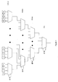
- Figure 1 is a block diagram illustrating a circuit using cascaded multiplexers in order to fetch a value from the array. Similar groups of cascaded multiplexers may be used for retrieving values of B and V.
- EP 1,289,188 (A2 ) describes methods and apparatus for ARC4 processing in a cryptography engine.
- a multiple ported memory can be used to allow pipelined read and write access to values in memory.
- Coherency checking can be applied to provide that read-after-write and write-after-write consistency is maintained.
- Initialization of the memory can be improved with a reset feature occurring in a single cycle.
- Key shuffle and key stream generation can also be performed using a single core.
- a method for encrypting information includes obtaining a value A from an array having a plurality of values and determining a value B based on the value A in a first pipeline stage.
- a value V may be determined from the value A and the value B.
- the value V may then be exclusive ORed (XORed) with a data value that forms a portion of the information being encrypted.
- a first logic unit may included the first pipeline stage, while a second logic unit may include the second pipeline stage.
- the method and apparatus may apply to the initialization of the array and to encryption of information.
- the array may be stored in a plurality of flip-flops in one embodiment, or may be stored in one or more register files in another embodiment. Embodiments using other types of storage technology are also possible and contemplated.
- the method and apparatus may also be used for decrypting information.
- the first and/or second pipeline stages may also be divided into substages in order to implement pipelines having a greater number of stages, e.g., 3-stage pipelines, 4-stage pipelines, and so on.
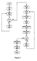
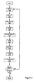
- FIG. 2 a flow diagram of one embodiment of a method of initializing an array for an encryption algorithm using array shifting is shown.
- method 200 corresponds with Procedure 3 shown below.
- index values i is set to zero while index value while j is set to one (3.2 of the procedure, item 210 of the flowchart).
- Each of these values is used to determine the position of a value in the array that is to be read when the array is being initialized (or, as will be discussed below, when the array is being used for encryption.
- the initialization procedure enters a loop (3.3).
- the array includes 256 positions, and thus the execution of the loop includes 256 iterations. Embodiments where the array is larger or smaller are possible and contemplated.
- a value A is obtained from the first position in the array, S[0] (3.3, item 212).
- the value A is read from the first array position for each iteration of the initialization.
- the method calculates a value of the index value j (3.3.2, item 214).
- the value of K [i] is a key value received from a key sequence used to initialize the array.
- the value of 1 is subtracted during the calculation of j .
- a second value B is read from the j th position of the array, S[j] (3.3.3, item 216).
- a swap operation may be performed (3.3.4, 3.3.5, item 218).
- the swap operation involves writing the value of B into the S[0] position of the array and the value of A into the S[j] position.
- the value of A is obtained from the first array position for each iteration and the value B is written into the first array position for each iteration.
- the array is shifted, with each value of S[k] being overwritten by the value of S[k+1] (3.3.6, item 220).
- the value present in the S[3] array position is written into the S[2] position
- the value in the S[2] position is written into the S[1] position
- the value in the S[1] position is written into the S[0] position
- the value in the S[0] position is written into the last array position (S[255] in this embodiment) during the shift operation.
- index value i is incremented (item 224).
- execution of the loop is terminated and another array shift operation takes place (3.4, item 226).
- the array shift operation is identical to the one that took place during the execution of the loop.
- the index values i and j are set to zero and one, respectively, following termination of loop execution (3.6, item 228).
- Table 3 illustrates the initialization of an array using Procedure 3 described above.
- the array shown here has been restricted to 8 elements, although the basic principles still apply.
- the initialization of the array illustrated in Table 3 is performed using a key sequence of 1, 2, 4, 2, 7, 6, 3, 5 (these are the values of K [i]).
- the initialization for this example progresses through eight iterations, with each iteration producing an S array, an S-swap array (due to the swap operation in 3.3.4 and 3.3.5) and an S-shift array resulting from the shift operation. In 3.4, the array is shifted one extra time.
- Hardware for performing the initialization procedure may include a 256-to-1 multiplexer for this embodiment (or in general, an N-to-1 multiplexer, wherein N is the number of elements in the array) for reading the value B from S[j].
- each array location may be associated with a comparator for the storing of the value A, which may be performed by sending A to each array position and comparing the value of j with the location indexes. When a match is found with between j and a given location index, the value of A is written into the corresponding location.
- Method 300 corresponds to Procedure 4 shown below.
- Method 300 begins with the reading of the value A from the first position of the array, S[0] (4.2, item 302).
- the value of A is read from the first array position for each iteration of the encryption performed by Procedure 4.
- the value B is determined by reading the S[j] position of the array (4.3, item 306).
- a swap operation is then performed in 4.4 and 4.5 (item 308) by writing the value A to S[j] and value B to S[0].
- index value i is incremented.
- the value V is read from the g th position of the array, S[g] (4.8, item 316). After reading the value of V from the array, a data byte is encrypted by XORing it with V (4.9, item 318). It is noted that in this embodiment, the values of A, B, V , and the amount of data encrypted in one iteration are each one byte (8 bits) in length. However, embodiments may be implemented using larger or smaller blocks of data.
- the S array is shifted (4.10, item 320) so that the next value of A to be read is in the S[0] position for the next iteration, if any.
- Table 4 below illustrates the generation of the V values for the encryption of Procedure 4, using the 8-element array initialized using Procedure 3.
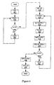
- Figure 4 is a flow diagram of another embodiment of initializing an array for an encryption algorithm using array shifting, Method 400 of Figure 4 is associated with Procedure 5 below.
- Procedure 5 is similar to array initialization Procedure 3 discussed above. However, instead of shifting the array at the end of the loop as in Procedure 3, the array is shifted after determining the value B . In general, the array shifting may be done any time within the loop. However, changing the point in the procedure when the array is shifted may alter some of its steps. In the case of Procedure 5, the steps prior to shifting the array are identical to those of Procedure 3 (e.g., A is read from the first array position S[0], index value j is computed in the same manner, etc.). The swap operation in Procedure 5 is performed by assigning the value B to the last position in the array, S[255], and assigning the value of A to the S[j-1] position of the array.
- Procedure 5 also differs from Procedure 3 in that the index value i is set to one while the index value j is reset to zero in the procedure's final steps.
- Table 5 illustrates the initialization using an exemplary 8-element array for the sake of simplicity.
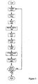
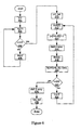
- FIG. 5 a flow diagram of another embodiment of a method of generating an encryption byte using array shifting is shown.
- Method 500 shown in Figure 5 is associated with the encryption algorithm of Procedure 6 shown below.
- Procedure 6 may be used to perform encryption utilizing an array generated according to Procedure 5 above.
- Procedure 6 is similar to Procedure 5 in that the shifting operation (6.4, item 508) occurs just after the fetching of value B from the array.
- the swap operation is performed in the same manner as in Procedure 5, with value B being written into the S[255] position and the value A being written into the S[j-1] position.
- the remainder of the procedure includes the incrementing of index value i (6.7, item 514), calculating index value g (6.8, item 516), reading a value of V from the g th position of the array (6.9, item 518), and XORing V with a byte of data to be encrypted (6.10, item 520).
- Table 6 below illustrates the generation of the V values for encryption performed by Procedure 6 using the array initialized in the example associated with Procedure 5.
- Figure 6 is a flow diagram of another embodiment of initializing an array for an encryption algorithm using array shifting.
- Method 600 shown in Figure 6 is associated with Procedure 7 below.
- Procedure 7 differs in that the shifting of the array occurs before the reading of the value B .
- Table 7 illustrates the performance of Procedure 7 using an exemplary 8-element array.
- the value A is read from the S[1] position in this embodiment (7.3.1, item 612).
- the swap operation occurs in 7.3.5 and 7.3.6 (items 612 and 614, respectively)
- B can be written into the S[0] position and A can be written into the S[j] position. This ensures that the correct values of A and B will be read for subsequent iterations of the loop.
- index values i and j are reset to zero after exiting the loop.
- FIG. 7 a flow diagram of another embodiment of a method of generating an encryption byte using array shifting is shown.
- the encryption procedure of method 700 is associated with Procedure 8 shown below.
- Procedure 8 is associated with array initialization Procedure 7, and thus the shifting of the array (8.3, item 706) occurs just after calculating the index value j (8.2, item 704).
- An example of the generation of the V values using Procedure 8 using the array initialized in the example associated with Procedure 7 is shown below in Table 8.
- the array may be shifted at any time during the procedure providing the appropriate modifications are made to ensure that A and B are read from (and written into) the correct location. Furthermore, the shifting of the array during the execution of these procedures allows value A to be read from the same array location with each iteration. Reading A from the same location each iteration may significantly reduce the amount of delay present in comparison to embodiments where A may be read from a different location in each iteration. Furthermore, reading A from the same location each iteration may allow for the elimination of some circuitry, such as an array of multiplexers forming an N-to-1 multiplexer (where N is the number of array elements, e.g., 256) may also be eliminated.
- N is the number of array elements, e.g., 256
- N-to-1 multiplexer may be used to obtain a value from an arbitrary position in the array, where N is the number of elements (e.g. 256).
- An N-to-1 multiplexer may be implemented using an array of multiplexers, such as that shown in Figure 1 .
- A may be read from the same array position for each iteration of the procedure being performed.
- N-to-1 multiplexers may be required only for the reading of the values B and V.
- Figures 8 , 9 and 10 illustrate embodiments of hardware implementations that may be used to pipeline the initialization and encryption procedures.
- Figures 8 is associated with all shifting array embodiments.
- Figure 9 is associated with initialization Procedure 5 and encryption Procedure 6.
- Figure 10 is associated with Procedure 7 up through step 7.3.4 and then with Procedure 5 from step 5.3.3.
- Figure 10 is associated with Procedure 8 up through step 8.4 and then with Procedure 6 from step 6.3.
- embodiments based on the other initialization and encryption procedures are also possible and contemplated (including those disclosed herein), and may be realized with modifications to the embodiments shown.
- array element circuit (AEC) 800 includes multiplexer 805 and flip-flop 810. Although single-bit implementations of the multiplexer and flip-flop are shown here, the circuit may be considered to be a multi-bit implementation having the bit-width of a value stored in an array element (e.g. 8 bits). Alternatively, the diagram may be viewed as being associated one of a plurality of bits in a given bit position.
- multiplexer 805 is a 4-to-1 multiplexer with inputs for S[k], S[k+1], A, and k.
- a value of k is selected only on the first clock cycle of an initialization procedure, and implements the entire first loop of Figure 4 since it is applied simultaneously to all positions of the S array.
- the output R[k] of multiplexer 805 is coupled to the input of flip-flop 810.
- Flip-flop 810 is one of many different types of storage devices that may be used to store values for an array.
- S[k] The value of S[k] is selected during the encryption procedure when there is no data to encrypt for a particular iteration.
- the S[k] input to the multiplexer is coupled to the output of flip-flop 810.
- the value of S[k+1] is selected.
- multiplexer 805 will allow a value stored in the next element of the array to propagate through to flip-flop 810. For example, when this selection is made, the value stored in S[3] is written into S[2], the value stored (prior to being overwritten by the value from S[3]) in S[2] is written to S[1], and so forth. Therefore, selecting of the S[k+1] input allows the shift operation to take place.
- A The selection of the A input allows the value of A to be written into the array location during the swap operation.
- A is written to S[j-1] location.
- the embodiment in which AEC 800 is implemented may function by sending value A to the multiplexer select inputs for each element in the array while sending the value of ( j - 1) to a comparator (not shown) in each AEC 800. When the comparator finds a match with the array element corresponding the value of ( j - 1), the value of A may be selected by the multiplexer inputs, thereby allowing it to propagate through to be stored in the flip-flops.
- the embodiment shown herein may be associated with Procedures 5 and 6, and thus the value of B is always written into the S[255] position.
- the embodiment shown herein may be modified for other ones of the procedures presented herein.
- the A input to the multiplexer may be coupled to allow either the values of A or B to propagate through for embodiments where B may be written to any one of the array elements during the swap operation.
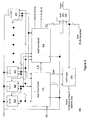
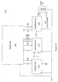
- FIG. 9 a block diagram of one embodiment of a pipelining circuit for an encryption algorithm utilizing array shifting is shown.
- the embodiment shown here in Figure 9 is associated with Procedures 5 and 6, although alternate embodiments designed to work with other procedures including those disclosed herein are possible and contemplated.
- Encryption circuit 900 includes a plurality of AECs 800, one for each element of the array.
- Each AEC 800 may include multiplexers for selection, flip-flops for storage, and may also include comparison logic for comparing a received index value with the index value of that particular array position.
- An output of each of the AECs-800s is fed back to an input so that the value of that array position can be maintained for any iteration wherein no data value is to be encrypted (e.g. when S[k] is selected as discussed above).
- a majority of the elements also have an input that is coupled to the output of a next element in the array. This allows the shifting operation to take place when the S[k+1] input is selected as discussed above.
- Encryption circuit 900 includes two add/fetch units 910 that may perform similar functions. Each add/fetch unit 910 may make up one or more pipeline stages. For example, add/fetch unit #1 may comprise the first pipeline stage for two-stage pipelines, or the first two pipeline stages for the 4-stage pipelines. Add/fetch unit #2 may comprise the 2nd pipeline stage for 2-stage embodiments or the 3rd and 4th stages for 4-stage embodiments.
- Add/fetch unit #1 is coupled to receive the output provided by each of the AEC's of the array, and thus may include an array of multiplexers for elements 0-255.
- Add/fetch unit 1 is coupled to read value A from the AEC 0, calculate index value j , and subsequently fetch value B from the S[j] position of the array.
- Add fetch unit #1 is also coupled to receive a key sequence through the K[i] input during the initialization process
- add/fetch unit is configured to generate a 'shift' signal which initiates the shifting.
- Add/fetch unit #2 is coupled to receive the values A and B from add/fetch unit #1.
- add/fetch unit #2 is coupled to write B into S[255] and A into S[j-1] when during a swap operation.
- add/fetch unit #2 may be coupled to write values A and B to locations other than S[j-1] and S[255], respectively.
- Add/fetch unit #2 also increments index value i and calculates index value g .
- add/fetch unit #2 may fetch the value V [g] from the array.
- V [g] is then provided as an output to XOR unit 920, where it is XOR'ed with the data byte to be encrypted for that iteration.
- Select logic 930 is coupled to receive the calculated index value j from add fetch unit #1, and in turn calculate [j-1] to determine which element A is to be written into during a swap operation. Select logic 930 is also coupled to receive a shift signal from add/fetch unit. When asserted, the shift signal invokes a shift of the array, and thus select logic 930 provides signals to the select inputs of multiplexers in AEC's 800 in order to cause the values of each S[k+1] to be stored in the S[k] position (with the exception of S[255], which stored the value previously held in S[0]).
- select logic 930 may provide signals separately to each AEC 800 in order to allow elements to be written into individually (as when A is written to the S[j-1] position during a swap).
- each AEC 800 may include comparison logic that allows the select signals to propagate to the multiplexer select inputs, and may thus allow an array element to be addressed individually such that A (and/or B in some embodiments) can be written to a desired array position for a swap operation.
- Select logic 930 may also receive a signal associated with the information to be encrypted indicating that no data is to be encrypted on a given iteration.
- Each of the various components of encryption circuit 900 is coupled to receive a clock signal.
- each of the add/fetch units 910 may be performed in a single clock cycle.
- the functions of each add/fetch unit may be performed in two clock cycles. It is also noted that other embodiments implementing pipelines other than the 2- and 4-stage pipelines discussed here.
- Tables 9A and 9B shown below illustrate the operations of a two stage pipeline in accordance with Procedures 5 and 6 and the circuit embodiments shown in Figures 8 and 9 . It should be noted that the values of K in the first pipeline stage are used for the initialization procedure, and will have a value of zero during the encryption procedure.
- Table 10 illustrates both an initialization and encryption of the pipelined embodiment of Tables 9A and 9B.
- index value i is initially set to zero and incremented to one during the extra clock cycle.
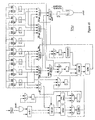
- Figure 10 is a schematic diagram of an exemplary embodiment of a circuit that may be used for pipelining an encryption algorithm.
- the circuit 1050 illustrated in Figure 10 is configured for a 4-stage pipeline and an 8-element array (for the purposes of clarity), and illustrates one possible way a circuit may be implemented for performing the initialization and encryption procedures.
- Tables 11A and 11B shown below illustrate the operation of a 4-stage pipeline. This illustration combines Procedure 5 with Procedure 7 and Procedure 6 with Procedure 8.
- the first pipeline stage uses Procedure 7 through step 7.3.2.
- the array is shifted as in step 7.3.3. Since the shifting of the pipeline occurs on the clock edge, it may be thought of as happening "between" the pipeline stages.
- Step 7.3.4 is the same as step 5.3.3 and is performed in the second pipeline stage. Steps 5.3.4, 5.3.5 and 5.3.6 are accomplished on the next clock edge.
- the first pipeline stage uses Procedure 8 up through step 8.2. On the clock edge at the end of the first pipeline stage, the array is shifted as in step 8.3. Step 8.4 is the same as step 6.3 and is performed in the second pipeline stage. Steps 6.4, 6.5, and 6.6 are accomplished on the next clock edge. Steps 6.7 and 6.8 are performed in the third pipeline stage. Step 6.9 involves a cascade of multiplexers as shown in Figure 1 and may be in the third pipeline stage, the fourth pipeline stage, or split with the early part of the cascade in the third pipeline stage and the later part in the fourth pipeline stage.
- step 6.10 is also executed in the fourth pipeline stage (or in some embodiments, a 5 th pipeline stage). Finally, if step 6.9 is entirely in the third pipeline stage, then step 6.10 may be executed in either the third pipeline stage or the fourth pipeline stage. If step 6.10 is executed in the third pipeline stage, then there is no fourth pipeline stage but the encryption result is available late in the third clock cycle. If it is executed in a fourth pipeline stage, the encryption result is available early in the fourth clock cycle.
- Tables 11A and 11B show the case where the cascade of multiplexer to obtain V [g], step 6.9, are in the third pipeline stage and the XORing of the value of V [g] with the data to be encrypted, step 6.10, is in the fourth pipeline stage.
- Tables 11A and 11B illustrate how operations may be separated in order to form a 4-stage pipeline. Since the pipeline has 4 stages, an actual encryption does not take place until the fourth iteration. However, an encryption may be performed with each iteration beginning with the fourth (providing that data is provided for each iteration). If each pipeline stage is configured to perform its respective operations within one clock cycle, then one encryption for each clock cycle may occur.
- Table 12 further illustrates the operation of a 4-stage pipeline. It is noted that in the example shown that index value i is initially set to -1 and three extra clock cycles are added in order to fill the pipeline. Thus, encryption begins on the first clock cycle following extra clock #3.
- the examples above are directed to pipelining when a procedure involving array shifting is used for the initialization and encryption.
- the array shifting is performed in order to allow a data value (typically A ) to be read from the same location of the array for each iteration.
- a data value typically A
- pipelining of the encryption and initialization procedures can be accomplished without performing the array shifting.
- FIG 11A is a block diagram of another embodiment of a pipelining circuit for an encryption algorithm
- Encryption circuit 1100 instead of using the array element circuits of the embodiment shown in Figure 9 , stores array values in a register unit 1105 having one or more register files.
- Register unit 1105 may store the entire array. Each register address within register unit 1105 may be associated with one array position.
- Register unit 1105 may also be configured for multiple simultaneous reads.
- the register files of register unit 1105 include 3 read ports, and thus the contents of 3 different array addresses may be read at any given time.
- the register files of register unit 1105 may also include multiple write ports.
- each register file of register unit 1105 includes two write ports, allowing the simultaneous writing of two locations.
- the register files can simultaneously support three read operations and two write operation, thereby allowing operations to be conducted in parallel for a pipelined implementation.
- a 3- or 4-stage pipeline may be implemented.
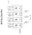
- Figure 11B shows one example of a register unit 1105.
- register unit 1105 includes four register files each having 64 entries (for 256 entries total).
- register unit 1105 may store an array having 256 elements with each array element corresponding to an entry in a register file.
- Figure 10B Also shown in Figure 10B are the three read ports and two write ports previously discussed.
- fetch/add unit 1110 performs the functions for a first pipeline stage.
- Fetch/add unit may provide the index i as an address to register unit 1105.
- register unit 1105 may return the value of A to fetch/add unit 1110 from the S[i] position of the array.
- Fetch/add unit 1110 also includes arithmetic circuitry for calculating the index value j .
- Fetch/swap unit 1115 may receive the calculated index value j and the value A from fetch/add unit 1110. The received index value j is then provided to register unit 1105 in order to obtain the value B from the S[j] position of the array. Fetch/swap unit 1115 also performs the swap operation by forwarding the value A to an address indicated by index value j (S[j]) and value B to an address indicated by index value i (S[i]) in register unit 1105. The index value g is also calculated by fetch/swap unit 1115.
- Fetch/encrypt unit 1120 is coupled to receive the index value g from fetch swap unit 1115.
- the index value g is provided by fetch/encrypt unit 1120 to register unit 1105, which returns value V from the S[g] position of the array.
- the value V retrieved from the array is then provided to XOR unit 1125, where it is XORed with a block of data (e.g. one byte) to be encrypted.
- XOR unit 1125 may occur in either the third clock cycle for a three-clock pipeline implementation of a fourth clock cycle for a four-clock pipeline implementation.
- the encryption result is available near the end of the third clock cycle, wherein in a four clock-pipeline, the encryption result is available early in the fourth clock cycle.
- the time of arrival within the clock cycle of the data byte (being encrypted) may be an important factor in deciding whether to implement a three-clock or a four-clock pipeline.
- each pipeline stage occurs simultaneously with respect to the operations of the other pipeline stages.
- the reading of values A , B, and V each occur simultaneously once the pipeline is full.
- Table 13 illustrates the operation for one embodiment of encryption using a 3-stage pipeline.
- the operations of each pipeline stage occur in a single clock cycle.
- an encryption of a data byte may occur with each successive clock cycle.
- operations in each pipeline stage are simultaneous with respect to each other.
- the value of V 1 being XORed with a data byte occurs simultaneously with the operations of stage 2 of the pipeline (reading B 2 , performing the swap operation, and calculating g 2 ), which in turn are simultaneous to operations occurring in stage 1 of the pipeline (reading A 3 , calculating j 3 ).
Landscapes
- Engineering & Computer Science (AREA)
- Computer Security & Cryptography (AREA)
- Computer Networks & Wireless Communication (AREA)
- Signal Processing (AREA)
- Storage Device Security (AREA)
Claims (21)
- Verfahren zum Verschlüsseln von Informationen, wobei das Verfahren die folgenden Schritte umfasst:in einer ersten Pipelinestufe (910):Erhalten eines Werts A aus einer Matrix mit mehreren Werten, wobei jeder der Werte an einem entsprechenden von mehreren Speicherorten (800) gespeichert ist; undBestimmen eines Werts B basierend auf dem Wert A;undin einer zweiten Pipelinestufe (910):Erhalten eines Werts V zum Verschlüsseln aus einer Position in der Matrix, die auf dem Wert A und dem Wert B basiert;Anwenden einer XOR-Verknüpfung (920) auf den Wert V und auf einen Datenwert, der einen Teil der Informationen bildet;wobei das Verfahren Iterationen umfasst, einschließlich:Verschieben der Matrix, um zu ermöglichen, für jede Iteration den Wert A aus demselben der mehreren Speicherorte in der Matrix zu erhalten; undErhalten des Werts A aus demselben der mehreren Speicherorte für jede Iteration.
- Verfahren nach Anspruch 1, wobei die Matrix unter Verwendung einer Verschlüsselungsschlüssel-Sequenz initialisiert wird.
- Verfahren nach Anspruch 1, wobei eine erste Iteration des Erhaltens und des Anwendens einer XOR-Verknüpfung in der zweiten Pipelinestufe gleichzeitig mit einer zweiten Iteration des Erhaltens und des Bestimmens in der ersten Pipelinestufe durchgeführt wird.
- Verfahren nach Anspruch 3, wobei die erste Iteration auf einem ersten Wert A in der Matrix basiert und wobei die zweite Iteration auf einem nächsten Wert A in der Matrix basiert.
- Verfahren nach Anspruch 3, ferner umfassend das Inkrementieren eines Indexwerts i während jeder Iteration und Rücksetzen des Wertes i auf null als Reaktion auf das Erreichen einer vorbestimmten Grenze.
- Verfahren nach Anspruch 1, wobei jeder der mehreren Werte an einem Speicherort gespeichert wird, der Flipflops umfasst.
- Verfahren nach Anspruch 6, wobei die erste Pipelinestufe eine erste Unterstufe und eine zweite Unterstufe beinhaltet, wobei das Erhalten des Werts A in der ersten Unterstufe durchgeführt wird und das Bestimmen des Werts B in der zweiten Unterstufe bestimmt wird.
- Verfahren nach Anspruch 6, wobei die zweite Pipelinestufe eine dritte Unterstufe und eine vierte Unterstufe beinhaltet, wobei ein Indexwert g basierend auf dem Wert A und dem Wert B und dem Wert V in der dritten Unterstufe bestimmt wird und das Anwenden der XOR-Verknüpfung in der vierten Unterstufe durchgeführt wird.
- Verfahren nach Anspruch 6, wobei die zweite Pipelinestufe eine dritte Unterstufe und eine vierte Unterstufe beinhaltet, wobei ein Indexwert g basierend auf dem Wert A und dem Wert B in der dritten Unterstufe bestimmt wird und wobei der Wert V und das Anwenden der XOR-Verknüpfung in der vierten Unterstufe durchgeführt werden.
- Verfahren nach Anspruch 1, wobei das Erhalten des Werts B das Bestimmen eines Index j umfasst, der auf dem Wert A basiert, wobei der Wert B das j-te Element der Matrix ist und wobei Bestimmen eines Werts für den Index j das Berechnen der Summe von j + A umfasst.
- Verfahren nach Anspruch 1, wobei das Erhalten des Werts V das Bestimmen der Summe aus den Werten A und B und das Lesen des g-ten Elements der Matrix umfasst, wobei g die Summe aus den Werten A und B ist.
- Verschlüsselungsvorrichtung, umfassend:mehrere Speicherorte (800), die dafür ausgelegt sind, eine Matrix mit mehreren Werten zu speichern, wobei jeder der Werte an einem entsprechenden der mehreren Speicherorte gespeichert wird; undeine erste Logikeinheit (910), die dafür ausgelegt ist, einen Wert A aus der Matrix zu lesen und einen auf dem Wert A basierenden Wert B zu bestimmen; undeine zweite Logikeinheit (910), die dafür ausgelegt ist einen Wert V zum Verschlüsseln aus einer Position in der Matrix, die auf dem Wert A und dem Wert B basiert, zu lesen und eine XOR-Verknüpfung (920) auf den Wert V und auf einen Datenwert anzuwenden, der einen Teil der zu verschlüsselnden Informationen bildet;wobei die erste Logikeinheit eine erste Pipelinestufe umfasst und die zweite Logikeinheit eine zweite Pipelinestufe umfasst;wobei die Verschlüsselungsvorrichtung dafür ausgelegt ist, Iterationen durchzuführen, und zu Folgendem ausgelegt ist:Verschieben der Matrix bis innerhalb der mehreren Speicherorte, um zu ermöglichen, für jede Iteration den Wert A aus demselben der mehreren Speicherorte in der Matrix zu lesen; undLesen des Werts A aus demselben der mehreren Speicherorte für jede Iteration.
- Verschlüsselungsvorrichtung nach Anspruch 12, wobei die Verschlüsselungsvorrichtung angeschlossen ist, um eine Verschlüsselungsschlüssel-Sequenz zum Initialisieren der Matrix zu empfangen.
- Verschlüsselungsvorrichtung nach Anspruch 12, wobei die zweite Pipelinestufe dafür ausgelegt ist, den Wert V aus der Position in der Matrix zu lesen, die auf dem Wert A und dem Wert B basiert, und eine XOR-Verknüpfung des Werts V mit einem Datenwert gleichzeitig mit der ersten Pipelinestufe anzuwenden, eine zweite Iteration des Lesens des Werts A aus der Matrix durchzuführen und einen auf dem Wert A basierenden Wert B zu berechnen.
- Verschlüsselungsvorrichtung nach Anspruch 14, wobei die erste Iteration auf einem ersten Wert A in der Matrix basiert und wobei die zweite Iteration auf einem nächsten Wert A in der Matrix basiert.
- Verschlüsselungsvorrichtung nach Anspruch 15, wobei die Verschlüsselungsvorrichtung ferner dafür ausgelegt ist, einen Indexwert i während jeder Iteration zu inkrementieren, und wobei die Verschlüsselungsvorrichtung dafür ausgelegt ist, den Wert i als Reaktion auf das Erreichen einer vorbestimmten Grenze auf null zurückzusetzen.
- Verschlüsselungsvorrichtung nach Anspruch 15, wobei jeder der mehreren Speicherorte Flipflops beinhaltet.
- Verschlüsselungsvorrichtung nach Anspruch 17, wobei die erste Pipelinestufe eine erste Unterstufe und eine zweite Unterstufe beinhaltet, wobei das Erhalten des Werts A in der ersten Unterstufe durchgeführt wird und das Bestimmen des Werts B in der zweiten Unterstufe bestimmt wird.
- Verschlüsselungsvorrichtung nach Anspruch 17, wobei die zweite Pipelinestufe eine dritte Unterstufe und eine vierte Unterstufe beinhaltet, wobei ein Indexwert g basierend auf dem Wert A und dem Wert B und ein Wert V basierend auf dem Wert g in der dritten Unterstufe bestimmt werden und wobei das XOR-Verknüpfen in der vierten Unterstufe durchgeführt wird.
- Verschlüsselungsvorrichtung nach Anspruch 15, wobei die erste Logikeinheit dafür ausgelegt ist, einen Indexwert j zu bestimmen, der auf dem Wert A basiert, wobei der Wert B das j-te Element der Matrix ist und wobei die erste Logikeinheit dafür ausgelegt ist, den Indexwert j zu bestimmen, der auf der Summe j + A basiert.
- Verschlüsselungsvorrichtung nach Anspruch 20, wobei die Verschlüsselungsvorrichtung ferner dafür ausgelegt ist, einen Indexwert g zu berechnen, wobei der Indexwert g die Summe aus dem Wert von A und dem Wert von B ist, wobei V das g-te Element der Matrix ist.
Applications Claiming Priority (2)
| Application Number | Priority Date | Filing Date | Title |
|---|---|---|---|
| US10/617,632 US7295672B2 (en) | 2003-07-11 | 2003-07-11 | Method and apparatus for fast RC4-like encryption |
| PCT/US2004/022248 WO2005008956A1 (en) | 2003-07-11 | 2004-07-09 | Method and apparatus for fast rc4-like encryption |
Publications (2)
| Publication Number | Publication Date |
|---|---|
| EP1649634A1 EP1649634A1 (de) | 2006-04-26 |
| EP1649634B1 true EP1649634B1 (de) | 2015-03-25 |
Family
ID=33565017
Family Applications (1)
| Application Number | Title | Priority Date | Filing Date |
|---|---|---|---|
| EP04777997.0A Expired - Lifetime EP1649634B1 (de) | 2003-07-11 | 2004-07-09 | Verfahren und vorrichtung zur schnellen rc4-verschlüsselung |
Country Status (3)
| Country | Link |
|---|---|
| US (1) | US7295672B2 (de) |
| EP (1) | EP1649634B1 (de) |
| WO (1) | WO2005008956A1 (de) |
Families Citing this family (8)
| Publication number | Priority date | Publication date | Assignee | Title |
|---|---|---|---|---|
| US8045707B2 (en) * | 2003-08-15 | 2011-10-25 | Broadcom Corporation | System and method for securing data |
| US7653196B2 (en) * | 2004-04-27 | 2010-01-26 | Intel Corporation | Apparatus and method for performing RC4 ciphering |
| GB2426673B (en) * | 2005-05-27 | 2010-02-10 | Sony Uk Ltd | Data processing apparatus for performing a cryptographic method |
| US20080215493A1 (en) * | 2007-03-02 | 2008-09-04 | Raymond Soo How Ong | Method and system for negotiation |
| US8560307B2 (en) * | 2008-01-28 | 2013-10-15 | Qualcomm Incorporated | Systems, methods, and apparatus for context suppression using receivers |
| US8533456B2 (en) | 2010-10-07 | 2013-09-10 | King Saud University | Accelerating stream cipher operations using single and grid systems |
| US8914616B2 (en) | 2011-12-02 | 2014-12-16 | Arm Limited | Exchanging physical to logical register mapping for obfuscation purpose when instruction of no operational impact is executed |
| US9201656B2 (en) * | 2011-12-02 | 2015-12-01 | Arm Limited | Data processing apparatus and method for performing register renaming for certain data processing operations without additional registers |
Family Cites Families (8)
| Publication number | Priority date | Publication date | Assignee | Title |
|---|---|---|---|---|
| US5485619A (en) * | 1993-12-29 | 1996-01-16 | International Business Machines Corporation | Array variable transformation system employing subscript table mapping to scalar loop indices |
| US6389535B1 (en) | 1997-06-30 | 2002-05-14 | Microsoft Corporation | Cryptographic protection of core data secrets |
| US6618806B1 (en) | 1998-04-01 | 2003-09-09 | Saflink Corporation | System and method for authenticating users in a computer network |
| US6549622B1 (en) * | 1998-11-23 | 2003-04-15 | Compaq Computer Corporation | System and method for a fast hardware implementation of RC4 |
| US6683954B1 (en) | 1999-10-23 | 2004-01-27 | Lockstream Corporation | Key encryption using a client-unique additional key for fraud prevention |
| US7403615B2 (en) * | 2001-08-24 | 2008-07-22 | Broadcom Corporation | Methods and apparatus for accelerating ARC4 processing |
| US7043017B2 (en) * | 2001-09-13 | 2006-05-09 | Freescale Semiconductor, Inc. | Key stream cipher device |
| US6980649B1 (en) * | 2001-12-10 | 2005-12-27 | Cisco Technology, Inc. | Hardware-based encryption/decryption employing dual ported memory and fast table initialization |
-
2003
- 2003-07-11 US US10/617,632 patent/US7295672B2/en not_active Expired - Lifetime
-
2004
- 2004-07-09 WO PCT/US2004/022248 patent/WO2005008956A1/en not_active Ceased
- 2004-07-09 EP EP04777997.0A patent/EP1649634B1/de not_active Expired - Lifetime
Also Published As
| Publication number | Publication date |
|---|---|
| US20050010527A1 (en) | 2005-01-13 |
| US7295672B2 (en) | 2007-11-13 |
| WO2005008956A1 (en) | 2005-01-27 |
| EP1649634A1 (de) | 2006-04-26 |
Similar Documents
| Publication | Publication Date | Title |
|---|---|---|
| US7142669B2 (en) | Circuit for generating hash values | |
| US7519795B2 (en) | Method and system for performing permutations with bit permutation instructions | |
| US8411853B2 (en) | Alternate galois field advanced encryption standard round | |
| US20020032551A1 (en) | Systems and methods for implementing hash algorithms | |
| US5943248A (en) | w-bit non-linear combiner for pseudo-random number generation | |
| US20020191792A1 (en) | Apparatus and method for a hash processing system using integrated message digest and secure hash architectures | |
| US20050213756A1 (en) | Round key generation for aes rijndael block cipher | |
| US7106860B1 (en) | System and method for executing Advanced Encryption Standard (AES) algorithm | |
| US7657757B2 (en) | Semiconductor device and method utilizing variable mode control with block ciphers | |
| Kahri et al. | High speed FPGA implementation of cryptographic KECCAK hash function crypto-processor | |
| US20020018562A1 (en) | Key scheduler for encryption apparatus using data encryption standard algorithm | |
| CN111756520A (zh) | 超低时延高级加密标准 | |
| US20040120518A1 (en) | Matrix multiplication for cryptographic processing | |
| EP1649634B1 (de) | Verfahren und vorrichtung zur schnellen rc4-verschlüsselung | |
| US7403615B2 (en) | Methods and apparatus for accelerating ARC4 processing | |
| US7340496B2 (en) | System and method for determining the Nth state of linear feedback shift registers | |
| US6931127B2 (en) | Encryption device using data encryption standard algorithm | |
| WO2002101982A1 (en) | Cryptographic apparatus and method with multiple port memory | |
| JP4612680B2 (ja) | Md5ダイジェスティングを実行する装置および方法 | |
| CN1795637B (zh) | 用于密钥扩展功能的低速存储器硬件实施的方法和设备 | |
| Hilewitz et al. | Accelerating the whirlpool hash function using parallel table lookup and fast cyclical permutation | |
| CN112202548A (zh) | 流加密密钥流生成方法、装置、电路和加密方法 | |
| US7401110B1 (en) | System, method and apparatus for an improved MD5 hash algorithm | |
| CN114553424A (zh) | Zuc-256流密码轻量级硬件系统 | |
| US12401495B1 (en) | Universal circuit device for selective block cipher cryptographic processing with space efficient configurational agility |
Legal Events
| Date | Code | Title | Description |
|---|---|---|---|
| PUAI | Public reference made under article 153(3) epc to a published international application that has entered the european phase |
Free format text: ORIGINAL CODE: 0009012 |
|
| 17P | Request for examination filed |
Effective date: 20060210 |
|
| AK | Designated contracting states |
Kind code of ref document: A1 Designated state(s): DE GB |
|
| DAX | Request for extension of the european patent (deleted) | ||
| RBV | Designated contracting states (corrected) |
Designated state(s): DE GB |
|
| 17Q | First examination report despatched |
Effective date: 20091027 |
|
| RAP1 | Party data changed (applicant data changed or rights of an application transferred) |
Owner name: ORACLE AMERICA, INC. |
|
| GRAP | Despatch of communication of intention to grant a patent |
Free format text: ORIGINAL CODE: EPIDOSNIGR1 |
|
| INTG | Intention to grant announced |
Effective date: 20140611 |
|
| GRAP | Despatch of communication of intention to grant a patent |
Free format text: ORIGINAL CODE: EPIDOSNIGR1 |
|
| INTG | Intention to grant announced |
Effective date: 20141027 |
|
| GRAS | Grant fee paid |
Free format text: ORIGINAL CODE: EPIDOSNIGR3 |
|
| GRAA | (expected) grant |
Free format text: ORIGINAL CODE: 0009210 |
|
| AK | Designated contracting states |
Kind code of ref document: B1 Designated state(s): DE GB |
|
| REG | Reference to a national code |
Ref country code: GB Ref legal event code: FG4D |
|
| REG | Reference to a national code |
Ref country code: DE Ref legal event code: R096 Ref document number: 602004046868 Country of ref document: DE Effective date: 20150507 |
|
| REG | Reference to a national code |
Ref country code: DE Ref legal event code: R097 Ref document number: 602004046868 Country of ref document: DE |
|
| PLBE | No opposition filed within time limit |
Free format text: ORIGINAL CODE: 0009261 |
|
| STAA | Information on the status of an ep patent application or granted ep patent |
Free format text: STATUS: NO OPPOSITION FILED WITHIN TIME LIMIT |
|
| 26N | No opposition filed |
Effective date: 20160105 |
|
| REG | Reference to a national code |
Ref country code: DE Ref legal event code: R082 Ref document number: 602004046868 Country of ref document: DE Representative=s name: D YOUNG & CO LLP, DE |
|
| P01 | Opt-out of the competence of the unified patent court (upc) registered |
Effective date: 20230522 |
|
| PGFP | Annual fee paid to national office [announced via postgrant information from national office to epo] |
Ref country code: GB Payment date: 20230601 Year of fee payment: 20 |
|
| PGFP | Annual fee paid to national office [announced via postgrant information from national office to epo] |
Ref country code: DE Payment date: 20230531 Year of fee payment: 20 |
|
| REG | Reference to a national code |
Ref country code: GB Ref legal event code: PE20 Expiry date: 20240708 |
|
| PG25 | Lapsed in a contracting state [announced via postgrant information from national office to epo] |
Ref country code: GB Free format text: LAPSE BECAUSE OF EXPIRATION OF PROTECTION Effective date: 20240708 |
|
| PG25 | Lapsed in a contracting state [announced via postgrant information from national office to epo] |
Ref country code: GB Free format text: LAPSE BECAUSE OF EXPIRATION OF PROTECTION Effective date: 20240708 |