EP1649751A2 - Dispositif de roulage - Google Patents
Dispositif de roulage Download PDFInfo
- Publication number
- EP1649751A2 EP1649751A2 EP05021752A EP05021752A EP1649751A2 EP 1649751 A2 EP1649751 A2 EP 1649751A2 EP 05021752 A EP05021752 A EP 05021752A EP 05021752 A EP05021752 A EP 05021752A EP 1649751 A2 EP1649751 A2 EP 1649751A2
- Authority
- EP
- European Patent Office
- Prior art keywords
- belt
- run
- band
- guide rails
- long roller
- Prior art date
- Legal status (The legal status is an assumption and is not a legal conclusion. Google has not performed a legal analysis and makes no representation as to the accuracy of the status listed.)
- Withdrawn
Links
- 238000005096 rolling process Methods 0.000 claims description 8
- 125000006850 spacer group Chemical group 0.000 abstract description 4
- 230000005540 biological transmission Effects 0.000 description 2
- 238000010276 construction Methods 0.000 description 2
- 238000000151 deposition Methods 0.000 description 2
- 238000000855 fermentation Methods 0.000 description 1
- 230000004151 fermentation Effects 0.000 description 1
- 238000009940 knitting Methods 0.000 description 1
- 238000000034 method Methods 0.000 description 1
- 230000000284 resting effect Effects 0.000 description 1
- 230000002441 reversible effect Effects 0.000 description 1
Images


Classifications
-
- A—HUMAN NECESSITIES
- A21—BAKING; EDIBLE DOUGHS
- A21C—MACHINES OR EQUIPMENT FOR MAKING OR PROCESSING DOUGHS; HANDLING BAKED ARTICLES MADE FROM DOUGH
- A21C7/00—Machines which homogenise the subdivided dough by working other than by kneading
- A21C7/01—Machines which homogenise the subdivided dough by working other than by kneading with endless bands
Definitions
- the invention relates to a long roller for long rolls of dough pieces according to the preamble of claim 1.
- Such a long roller is known from EP 1 104 650 A1.
- the advantage of this long roller is that it can be used either with an upper belt or else with a pressure board unit above the lower belt, without the need for the long roller to be designed deep in the conveying direction.
- the construction of the swing frame of the long roller for alternative pivoting of the upper band on the one hand or the pressure board unit on the other hand consuming.
- the invention is therefore based on the object, a long roller of the type mentioned in such a way that at least the same design quality is achieved with structurally lower cost.
- the guide rails according to the invention are provided in an upper belt.
- a lateral guidance of the long rolled dough pieces during rolling is possible, so that they are rolled very defined long.
- a precise final position control at the end of the long rolling process is possible.
- due to the movable tread of the upper belt compared to a long rolls with a print board unit achieved a much improved product quality.
- the rolling path for the long rolls of dough can be individually lengthened or shortened depending on the product to be produced.
- the result is a long roller with the combined advantages of upper belt and pressure board unit with side guide in comparison to the prior art much less complicated structural design.
- the upper belt can be divided, for example, into four upper single belts. A subdivision into a different number of upper single bands is possible.
- a drive of the upper single bands according to claim 3 is simple. Alternatively, it is, for. As for simultaneous long rolls of different products, possible to drive the individual bands independently. Finally, it is also possible to drive the upper band indirectly, in particular to derive the drive of the upper band from the drive of the lower band.
- An embodiment according to claim 4 allows a holder of the guide rails on the upper band-lower strand to an upper-band housing, which further simplifies the construction of the cross-roller.
- the embodiments according to claims 5 and 6 allow the use of a height-adjustable long-wheeler, in which at each height or distance adjustment between upper and lower band secure lateral guidance is ensured by the guide rails.
- a holder via slots is possible.
- the upper band can be relatively height-adjustable, in particular to the lower band, so that not only cylindrical but also wedge-shaped dough pieces can be rolled in length. Such a wedge shape is advantageous for rolling dough pieces with pointed ends, for example for bolillos.
- the distance specification from top to bottom band over the bandwidth can be made by spacer pins or by insert wedges.
- the dough pieces 2 have a Teigteil- and circular knitting machine 1, divided in the known manner dough pieces 2 and round worked in a known manner.
- the dough pieces 2 are fed after the rounding in a proofer 3, in which they circulate in not shown in detail hangings of endless circulating chains 4 and subjected to a fermentation process.
- a removal belt 5 of the proofer 3 the dough pieces 2 are transferred to a long roller 6, from where they then reach a depositing device 7.
- the dough pieces 2 it may be z.
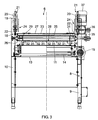
- B cylindrical dough pieces, to deal with dough pieces with pointed ends or rolled up pieces of dough. This basic structure of a roll-along arrangement is customary and known, as far as it is not the structure of the long-roller 6, which is shown in detail in FIGS. 2 and 3.
- the long roller 6 comprises a machine frame 8, which is supported by support feet 9 on the ground.
- Part of the machine frame 8 is a base frame 10, which is provided on its upper side with a table-like, flat plate 11.
- an endless lower belt 12 is supported, which is guided over mounted on an intermediate plane 13 of the base frame 10 driving and deflection rollers 14, wherein one of the drive rollers 14 is driven by a drive motor 15.
- the lower band 12 is guided over a belt tensioning device formed by the deflection rollers 14.
- the drive of the lower belt 12 is such that a resting on the plate 11 lower belt upper strand 16 is moved in the transport direction 17 of the dough pieces 2.
- the transport direction 17 is also referred to below as the running direction.
- a support frame 18 which has two gallows-like arms 19 which terminate above the plate 11.
- cylinders 20 are each flanged to a piston-cylinder lifting drive 21.
- a horizontally extending support plate 23 is fixed, which, like the piston-cylinder linear actuator 21 is part of a holding device 24 with which an upper belt 25 is supported above the lower belt 12.
- This holder is such that a tilting of the normal of the support plate 23 to the longitudinal axis of the piston 22 by a certain angle is possible.
- a top-belt housing 26 Supported by a top-belt housing 26 is a substantially horizontally extending counter-plate 27. At this a lower run 28 guided underneath the upper belt 25 is supported.
- the upper belt 25 is guided within the upper belt housing 26 via a drive roller 29 and a plurality of deflection rollers 30. Two of the deflection rollers 30 form a belt tensioning device for the upper belt 25.
- the upper belt 25 is subdivided into a total of four upper individual belts 31 (compare Fig. 3). The latter run parallel to each other. All upper single bands 31 are driven together by the drive roller 29. In each case between two adjacent upper individual bands 31, a guide strip 32 is arranged in the region of the upper band lower run 28. Two further guide rails 32 limit the upper belt lower run 28 laterally, so that a total of five guide rails 32 are present. A typical distance between two adjacent guide rails 32 is 135 mm.
- the guide rails 32 thus extend in the transport or running direction 17.
- the guide rails 32 extend upwardly between the upper single bands 31 through the plane of the upper band lower run 28 therethrough.
- the support plate 23 facing end face of the guide rails 32 has a recess 33 for the band-tensioning device for the upper belt 25.
- the opposite, the lower belt upper strand 16 facing support end face 34 of the guide rails 32 is made straight and flat, so that the guide rails 32 rest in the working position of the long roller 6 with the entire support end face 34 on the lower belt upper run 16.
- the guide rails 32 are not rigidly connected to the upper-band housing 26, but executed in a correspondingly shaped through openings of the counter-plate 27 hubbeweglich. They are in a manner not shown on the upper band case 26 against secured a fall down. This backup can z. B. by means of a slot screw pairing or more such pairings.
- the drive roller 29 is driven via a transmission belt 35 and a transmission roller 36 from an upper belt drive motor 37, which is also fixed to the support plate 23.
- the piston-cylinder lifting drive 21 is used for coarse adjustment of the height of the upper belt lower run 28 on the lower belt upper run 16 in the working position of the long roller 6.
- the lower belt upper run 16 and the upper belt lower run 28 define a channel in which due to relative speeds of lower band 12 and upper band 25 against each other, the dough pieces 2 are rolled long.
- This channel is divided by the guide rails 32 into four sub-channels.
- the long rolled in these sub-channels dough pieces 2 are guided laterally during the long rolling of the guide rails 32.
- the dough pieces 2 are present at the end of the long rolling process with a precisely defined final position. This ensures a defined transfer of the long rolled dough pieces 2 from the long roller 6 to the depositing device 7.
- a typical diameter of the long rolled dough pieces 2 is 70 mm.
- the drive motors 15 and 37 are speed controlled and reversible, so that the Langroll process can be controlled accurately.
- the exact height of the lower run 28 above the upper run 16 and the inclination of the lower run 28 to the upper run 16 are defined by spacer pins 38, which are mounted finely adjustable in height in the base frame 10. In the working position of the long roller 6, the counter plate 27 is supported on the free upper ends of the spacer pins 38.
- the guide rails 32 Due to the Hubbewegige the guide rails 32 to the upper band housing 26, the guide rails 32 a distance adjustment between upper band Untertrum 28 and Unterband-Obertrum 16 follow, so that at each set distance with their support end faces 34 at the top of the lower band upper run 16th issue. This ensures at differently adjusted height of the upper band lower strand 28 to the lower band upper strand 16 that the guide rails 32 extend completely between the bottom of the upper band lower strand 28 and the top of the lower band upper run 16. At each set distance, therefore, a lateral guidance of the dough pieces 2 is given by the guide rails 32.
- the piston-cylinder lifting drive 21 may be pneumatically, hydraulically or electrically actuated.
- the drive motors 15, 37 are designed as electric motors.
Landscapes
- Life Sciences & Earth Sciences (AREA)
- Engineering & Computer Science (AREA)
- Food Science & Technology (AREA)
- Manufacturing And Processing Devices For Dough (AREA)
Applications Claiming Priority (1)
| Application Number | Priority Date | Filing Date | Title |
|---|---|---|---|
| DE200410051683 DE102004051683A1 (de) | 2004-10-23 | 2004-10-23 | Langroller |
Publications (2)
| Publication Number | Publication Date |
|---|---|
| EP1649751A2 true EP1649751A2 (fr) | 2006-04-26 |
| EP1649751A3 EP1649751A3 (fr) | 2008-07-23 |
Family
ID=35709055
Family Applications (1)
| Application Number | Title | Priority Date | Filing Date |
|---|---|---|---|
| EP05021752A Withdrawn EP1649751A3 (fr) | 2004-10-23 | 2005-10-06 | Dispositif de roulage |
Country Status (2)
| Country | Link |
|---|---|
| EP (1) | EP1649751A3 (fr) |
| DE (1) | DE102004051683A1 (fr) |
Citations (2)
| Publication number | Priority date | Publication date | Assignee | Title |
|---|---|---|---|---|
| AU548075B2 (en) | 1983-05-05 | 1985-11-21 | Moffat Pty Limited | Endless belt bread shaper with side plate assemblies |
| EP1104650A1 (fr) | 1999-12-03 | 2001-06-06 | Werner & Pfleiderer Lebensmitteltechnik GmbH | Dispositif de roulage pour l'étirage de morceaux de pâte |
Family Cites Families (11)
| Publication number | Priority date | Publication date | Assignee | Title |
|---|---|---|---|---|
| US795581A (en) * | 1898-02-19 | 1905-07-25 | Ward Corby Company | Machine for working and shaping dough and the like. |
| DE597051C (de) * | 1931-10-11 | 1934-05-16 | Arthur Mairich | Einfuehrungsvorrichtung fuer Teigstuecke in eine Wirkmaschine |
| US2746401A (en) * | 1950-07-28 | 1956-05-22 | Irving M Archer | Dough rolling mechanism of a dough molding machine |
| US3116703A (en) * | 1960-09-01 | 1964-01-07 | Interstate Bakeries Corp | Loaf coiling bread molding machine |
| AU4925085A (en) * | 1984-11-09 | 1986-05-15 | Baker Perkins Exports Pty. Ltd. | Bread moulder |
| DE3707330C2 (de) * | 1987-03-07 | 1997-05-07 | Josef Hoeckmann | Vorrichtung zum kontinuierlichen Langwirken und Einschneiden von Backteigen, inbesondere von Brötchenteigen, unterschiedlicher Konsistenz |
| US4976600A (en) * | 1988-06-21 | 1990-12-11 | Apv Baker Pty Ltd. | Bread molders |
| FR2650481B1 (fr) * | 1989-08-04 | 1993-05-07 | Bertrand Machines | Dispositif de positionnement, de calibrage et de mise en forme de produits cylindriques a pate molle et calibreuse equipee de ce dispositif |
| FR2788936B3 (fr) * | 1999-02-03 | 2001-03-02 | Merand Mecapate Sa | Faconneuse semi-verticale |
| DE29921323U1 (de) * | 1999-12-03 | 2000-02-10 | Werner & Pfleiderer Lebensmitteltechnik GmbH, 91550 Dinkelsbühl | Langroller mit Druckbrett-Einheit |
| GB0223041D0 (en) * | 2002-10-04 | 2002-11-13 | Bakenomics Pty Ltd | Dough moulder |
-
2004
- 2004-10-23 DE DE200410051683 patent/DE102004051683A1/de not_active Withdrawn
-
2005
- 2005-10-06 EP EP05021752A patent/EP1649751A3/fr not_active Withdrawn
Patent Citations (2)
| Publication number | Priority date | Publication date | Assignee | Title |
|---|---|---|---|---|
| AU548075B2 (en) | 1983-05-05 | 1985-11-21 | Moffat Pty Limited | Endless belt bread shaper with side plate assemblies |
| EP1104650A1 (fr) | 1999-12-03 | 2001-06-06 | Werner & Pfleiderer Lebensmitteltechnik GmbH | Dispositif de roulage pour l'étirage de morceaux de pâte |
Also Published As
| Publication number | Publication date |
|---|---|
| EP1649751A3 (fr) | 2008-07-23 |
| DE102004051683A1 (de) | 2006-04-27 |
Similar Documents
| Publication | Publication Date | Title |
|---|---|---|
| DE3817583A1 (de) | Verbesserte schneidmaschine | |
| EP2539253B1 (fr) | Dispositif de régulation de l'alignement d'une courroie | |
| DE19946531A1 (de) | Senkrechtförderer für eine Palettiervorrichtung | |
| DE3885019T2 (de) | Verfahren und Vorrichtung zum Richten eines metallischen Bandes. | |
| EP2563694B1 (fr) | Transporteur à bande courbée | |
| EP0289744B1 (fr) | Convoyeur pour les corps cylindriques des boîtes à une machine à souder les boîtes | |
| EP2143550B1 (fr) | Dispositif de fabrication de corps creux en feuilles de plastique déformables thermoplastiques | |
| EP3331792B1 (fr) | Dispositif de remplissage d'un pot de filature avec un ruban de fibres | |
| EP1362817B1 (fr) | Dispositif pour pousser des produit imprimés empilés sur une table | |
| EP0694019A1 (fr) | Dispositif pour separer un produit d'une bande defilant en continu | |
| WO2019057577A1 (fr) | Rouleau de four, dispositif de transport équipé de ce dernier et procédé de fonctionnement associé | |
| DE60118011T2 (de) | Fertingungsstrasse für nahrungsmittelprodukte | |
| EP1649751A2 (fr) | Dispositif de roulage | |
| WO2011089044A1 (fr) | Dispositif et procédé de guidage de bandes à assembler entre elles le long de leurs arêtes longitudinales | |
| EP3126071B1 (fr) | Dispositif d'avance et de dressage | |
| EP2457443B1 (fr) | Procédé de torsion mécanique de bandes de pâte | |
| EP1937560B1 (fr) | Dispositif d'étiquetage de pots formés dans une bande de matériau d'emballage | |
| DE2063427B2 (de) | Spaltmaschine zum aufspalten von materialbloecken aus weichem werkstoff, insbesondere aus schaumstoff | |
| DE4413878C2 (de) | Aufwickelvorrichtung zum gleichzeitigen Aufwickeln von mehreren Handtuchbahnen an einer Heißmangel | |
| DE10345846B4 (de) | Langroller zum Langrollen von Teigstücken | |
| EP1104650B1 (fr) | Dispositif de roulage pour l'étirage de morceaux de pâte | |
| DE602006001025T2 (de) | Maschine zum Herstellen von Flanschen für Trommeln für elektrische Kabel durch Nageln von Holzteilen | |
| WO1985002357A1 (fr) | Scie a ruban reglable a coupe multiple | |
| DE2261848C2 (fr) | ||
| DE2220553A1 (de) | Kontinuierlich arbeitende presse zum herstellen von platten, wie span-, faserplatten od.dgl |
Legal Events
| Date | Code | Title | Description |
|---|---|---|---|
| PUAI | Public reference made under article 153(3) epc to a published international application that has entered the european phase |
Free format text: ORIGINAL CODE: 0009012 |
|
| AK | Designated contracting states |
Kind code of ref document: A2 Designated state(s): AT BE BG CH CY CZ DE DK EE ES FI FR GB GR HU IE IS IT LI LT LU LV MC NL PL PT RO SE SI SK TR |
|
| AX | Request for extension of the european patent |
Extension state: AL BA HR MK YU |
|
| PUAL | Search report despatched |
Free format text: ORIGINAL CODE: 0009013 |
|
| AK | Designated contracting states |
Kind code of ref document: A3 Designated state(s): AT BE BG CH CY CZ DE DK EE ES FI FR GB GR HU IE IS IT LI LT LU LV MC NL PL PT RO SE SI SK TR |
|
| AX | Request for extension of the european patent |
Extension state: AL BA HR MK YU |
|
| 17P | Request for examination filed |
Effective date: 20081103 |
|
| AKX | Designation fees paid |
Designated state(s): AT BE BG CH CY CZ DE DK EE ES FI FR GB GR HU IE IS IT LI LT LU LV MC NL PL PT RO SE SI SK TR |
|
| STAA | Information on the status of an ep patent application or granted ep patent |
Free format text: STATUS: THE APPLICATION IS DEEMED TO BE WITHDRAWN |
|
| 18D | Application deemed to be withdrawn |
Effective date: 20100430 |