EP1649936A2 - Système ouvert de collecte de poudre de cabine - Google Patents
Système ouvert de collecte de poudre de cabine Download PDFInfo
- Publication number
- EP1649936A2 EP1649936A2 EP05028448A EP05028448A EP1649936A2 EP 1649936 A2 EP1649936 A2 EP 1649936A2 EP 05028448 A EP05028448 A EP 05028448A EP 05028448 A EP05028448 A EP 05028448A EP 1649936 A2 EP1649936 A2 EP 1649936A2
- Authority
- EP
- European Patent Office
- Prior art keywords
- powder
- paint
- air
- collectors
- reclamation
- Prior art date
- Legal status (The legal status is an assumption and is not a legal conclusion. Google has not performed a legal analysis and makes no representation as to the accuracy of the status listed.)
- Withdrawn
Links
Images

Classifications
-
- B—PERFORMING OPERATIONS; TRANSPORTING
- B05—SPRAYING OR ATOMISING IN GENERAL; APPLYING FLUENT MATERIALS TO SURFACES, IN GENERAL
- B05B—SPRAYING APPARATUS; ATOMISING APPARATUS; NOZZLES
- B05B14/00—Arrangements for collecting, re-using or eliminating excess spraying material
- B05B14/40—Arrangements for collecting, re-using or eliminating excess spraying material for use in spray booths
- B05B14/43—Arrangements for collecting, re-using or eliminating excess spraying material for use in spray booths by filtering the air charged with excess material
- B05B14/435—Arrangements for collecting, re-using or eliminating excess spraying material for use in spray booths by filtering the air charged with excess material with means for cleaning the filters by gas flow, e.g. blasts of air
-
- B—PERFORMING OPERATIONS; TRANSPORTING
- B05—SPRAYING OR ATOMISING IN GENERAL; APPLYING FLUENT MATERIALS TO SURFACES, IN GENERAL
- B05B—SPRAYING APPARATUS; ATOMISING APPARATUS; NOZZLES
- B05B14/00—Arrangements for collecting, re-using or eliminating excess spraying material
- B05B14/40—Arrangements for collecting, re-using or eliminating excess spraying material for use in spray booths
- B05B14/48—Arrangements for collecting, re-using or eliminating excess spraying material for use in spray booths specially adapted for particulate material
-
- B—PERFORMING OPERATIONS; TRANSPORTING
- B05—SPRAYING OR ATOMISING IN GENERAL; APPLYING FLUENT MATERIALS TO SURFACES, IN GENERAL
- B05B—SPRAYING APPARATUS; ATOMISING APPARATUS; NOZZLES
- B05B14/00—Arrangements for collecting, re-using or eliminating excess spraying material
- B05B14/40—Arrangements for collecting, re-using or eliminating excess spraying material for use in spray booths
- B05B14/43—Arrangements for collecting, re-using or eliminating excess spraying material for use in spray booths by filtering the air charged with excess material
-
- Y—GENERAL TAGGING OF NEW TECHNOLOGICAL DEVELOPMENTS; GENERAL TAGGING OF CROSS-SECTIONAL TECHNOLOGIES SPANNING OVER SEVERAL SECTIONS OF THE IPC; TECHNICAL SUBJECTS COVERED BY FORMER USPC CROSS-REFERENCE ART COLLECTIONS [XRACs] AND DIGESTS
- Y02—TECHNOLOGIES OR APPLICATIONS FOR MITIGATION OR ADAPTATION AGAINST CLIMATE CHANGE
- Y02P—CLIMATE CHANGE MITIGATION TECHNOLOGIES IN THE PRODUCTION OR PROCESSING OF GOODS
- Y02P70/00—Climate change mitigation technologies in the production process for final industrial or consumer products
- Y02P70/10—Greenhouse gas [GHG] capture, material saving, heat recovery or other energy efficient measures, e.g. motor control, characterised by manufacturing processes, e.g. for rolling metal or metal working
-
- Y—GENERAL TAGGING OF NEW TECHNOLOGICAL DEVELOPMENTS; GENERAL TAGGING OF CROSS-SECTIONAL TECHNOLOGIES SPANNING OVER SEVERAL SECTIONS OF THE IPC; TECHNICAL SUBJECTS COVERED BY FORMER USPC CROSS-REFERENCE ART COLLECTIONS [XRACs] AND DIGESTS
- Y10—TECHNICAL SUBJECTS COVERED BY FORMER USPC
- Y10S—TECHNICAL SUBJECTS COVERED BY FORMER USPC CROSS-REFERENCE ART COLLECTIONS [XRACs] AND DIGESTS
- Y10S118/00—Coating apparatus
- Y10S118/07—Hoods
-
- Y—GENERAL TAGGING OF NEW TECHNOLOGICAL DEVELOPMENTS; GENERAL TAGGING OF CROSS-SECTIONAL TECHNOLOGIES SPANNING OVER SEVERAL SECTIONS OF THE IPC; TECHNICAL SUBJECTS COVERED BY FORMER USPC CROSS-REFERENCE ART COLLECTIONS [XRACs] AND DIGESTS
- Y10—TECHNICAL SUBJECTS COVERED BY FORMER USPC
- Y10S—TECHNICAL SUBJECTS COVERED BY FORMER USPC CROSS-REFERENCE ART COLLECTIONS [XRACs] AND DIGESTS
- Y10S55/00—Gas separation
- Y10S55/46—Spray booths
Definitions
- the subject invention relates generally to an improved powder paint collection apparatus for use with a production powder paint application booth.
- a typical powder paint booth includes a powder paint reclamation system that increases the paint use efficiency upwards of 95%.
- This type of reclamation system includes a reclamation collector positioned beneath each zone of the paint both. Each zone will generally include several discrete collectors positioned along the length of the zone.
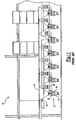
- a sectional view of a typical powder application booth is generally shown at 10 in Figure 1.
- Each reclamation collector 12 generally includes three sections.
- a lower section 14 functions as a hopper and collects powder paint funneled into the reclamation collector 12 to be returned the powder reclamation feed system (not shown) as is known to those of skill in the art of powder painting.
- a filter section 16 is disposed above the lower section 14 and includes a plurality of air filters 18 that are fluidly connected to an air return plenum 20, which returns air to an air inlet plenum (not shown) ultimately to create a downward draft of air inside the powder paint booth.
- Each of the prior art reclamation collectors 12 includes a separate air chamber 22 that rises from the filter section 16 to a porous floor 24 of the paint booth 10. Funnel walls 26 expand upwardly and outwardly from the filter section 16 and terminate at the porous floor 24 to collect powder paint particles and air from the entire surface of the porous floor 24 and funnel the particles and air into the lower section 14 and the filter section 16.
- a reclamation collector apparatus that does not have design dimensions that adversely affect the flow of air through the paint booth.
- a reclamation collector apparatus that does not adversely affect the flow of air through the paint booth would both improve the efficiency of the paint process by increasing the amount of paint recycled and reduce the number of paint defects on the product by reducing the potential of dirt type defects on the product.
- the present invention is a powder paint reclamation collector that improves the flow of fluidized paint particles through a paint booth and into a reclamation collector.
- the paint booth includes an air circulation system with an inlet plenum that provides downward draft of air through the paint booth and into a return plenum that receives filtered air from the reclamation collector to be recirculated through the paint booth.
- a plurality of discrete powder reclamation collectors are aligned in rows beneath a porous floor of an application chamber. Each collector includes an upper inlet receiving air and paint particles from the booth and a lower outlet for reclaiming particles.
- a continuous chamber is positioned above each row of reclamation collectors and is defined by having continuous side walls connecting the inlets of the reclamation collectors.
- the air chamber provides a continuous air plenum replacing the separate air funnels utilized in the prior art reclamation collectors. Air and particulate paint not adhered to the product is collected in each of the air chambers and is directed by the continuous plenum to the plurality of reclamation chambers.
- the utilization of a continuous air chamber that connects each of the reclamation collectors solves the problems identified with the prior art reclamation collector design.
- the inventive air chamber improves the consistency of the air flow velocity and the air pressure down the entire length of the booth.
- the open design allows powder to distribute more evenly in the collector filters reducing pressure drop that may occur when one air filter becomes plugged with particulate paint at a quicker rate than the other air filters in a given zone.
- the air filters may be positioned directly in a line of the air flow from the supply plenum, and do not need to be offset into external containers that are in fluid communication with the return plenum.
- Figure 1 is a side sectional view of a prior art powder paint reclamation apparatus
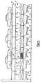
- Figure 2 is a cross-sectional elevation of the paint booth assembly showing the collector of the subject invention
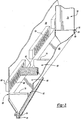
- Figure 3 is a perspective view of the reclamation collector of the subject invention.
- Figure 4 is a side sectional view of the powder reclamation apparatus of the subject invention showing separateness
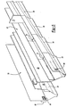
- Figure 5 is a perspective view of the inventive continuous air chamber.
- the booth includes a paint application chamber 32 wherein the powder paint is applied to a vehicle body 34 or other product.
- the application chamber 32 forms an elongated room into which the bodies 34 are conveyed for painting.
- a conveying device 28 such as, for example a conveyor, moves the products 34 through the application chamber 32.
- Paint application equipment 36 is disposed within the chamber 32 for applying the powder paint as is known in the art of powder painting.
- the application chamber 32 is enclosed by opposed walls 38, which separate the chamber 32 from control rooms 40 positioned on either side of the application chamber 32.
- the walls 38 are supported from below by a plurality of support members 42 that are arranged end to end along the entire length of the assembly 30.
- An air supply plenum 44 is affixed above the assembly 30 to provide fresh air to the application chamber 32.
- Inlet filters 46 are disposed within the plenum 44 to remove impurities from the fresh air that would otherwise result in paint defects on the car body 34.
- the fresh air provides a downward draft to the chamber 32 to force powder paint particles not adhered to the product 34 downward and out of the chamber 32.
- a plurality of grates 48 form the porous floor of the application chamber 32.
- the grates 48 are supported on one end by a conveyor support beam 50 and the other end by the support members 42.
- the support system is further disclosed in a copending U. S. Patent Application No. 09/728,337.
- the conveying device 28 operates in a channel 54 between the parallel conveyor support beams 50.
- the grates 48 allow air from the air supply plenum 44 and paint particles that have not adhered to the body 34 to pass through and into opposing air chambers 56.
- Figures 3, 4 and 5 show a continuous air chamber 56 disposed beneath each of the grates 48 (figure 4) thereby enclosing the bottom of the booth assembly 30 ( Figure 2).
- the continuous air chamber 56 includes opposed continuous side walls 69 that interconnect inlets 65 of discrete powder paint collectors 58.
- the continuous air chamber 56 defines a continuous air plenum communicating with opposing rows of collectors 58 for directing air and particulate paint not adhered to the product 34 into each of the reclamation collectors 58 as will be explained further below.
- the plurality of discrete powder reclamation collectors 58 enclose the bottom of each air chamber 56 preventing air and particulate paint from escaping out of the booth assembly 30 ( Figure 2) and into the environment surrounding the booth assembly 30.
- Each reclamation collector 58 defines a filter chamber 60 wherein a plurality of air filters 62 are disposed. Air is drawn through the air filter 62 and into the air return plenum 20 and routed through a filter house 64 before being returned to the air supply plenum 44.
- each reclamation collector 58 includes a plurality of slots 66 disposed in a side wall 68 of the filter chamber 60.
- An air filter 62 is inserted in each slot 66 to prevent powder paint particles from exiting the reclamation collector 58 through one of the slots 66.
- the air return plenum 20 draws air through the filters 62 and subsequently through the slots 66.
- some of the slots 66 may be covered to prevent the particulate paint from exiting the reclamation collector 58.
- the number of air filters 62 utilized depend upon the amount of air required to exit the booth assembly 30 to balance the flow of air through the air assembly 30.
- a filter is utilized to filter the particulate paint from the return air routed through the air return plenum 20 such as is available from Herding Filter Company.
- the Herding filter utilizes sintered filtering technology that provides a uniform pressure drop over the entirety of the filter 62 surface area. It will be understood by those of skill in the art that other types of filters providing similar properties may also be used.
- an air supply baffle 68 provides a pulse of air in a direction opposite to that of the flow of air through the return plenum 20 to displace particulate powder collected on the surface of the air filter 62.
- the pulse of air may be initiated on a cyclical schedule or may be initiated upon detection of a pressure drop in the return plenum 20.
- FIG. 4 shows a side partial sectional view of the booth assembly 30 of the present invention.
- the booth assembly 30 is shown having a first application zone 70 and a second application zone 72.
- adjacent reclamation collectors 58 are adjoined by a common panel 74 bowed to define separate surfaces within each of the reclamation collectors 58. Therefore, within each zone 70, 72, the continuous air chamber 56 defines an open area.
- each zone may contain a different powder paint, such as, for example reclaim, virgin, and color specific paint
- the zones must be physically separated to prevent contamination from one zone 70, 72 to the adjacent zone 72, 70.
- a divider wall 75 is positioned between each zone across a width of the air chamber 56.
- the wall 75 is positioned between adjacent reclamation collectors 58 from each zone 70, 72. Otherwise, the adjacent reclamation collectors 58 from each zone 70, 72 would abut.
- Each of the adjacent reclamation collectors 58 include a flange 76 ( Figure 3), which abut at the periphery of the wall 74.
- the abutting flanges 76 each include a plurality of apertures 78 that align to define a hole through which a fastener 80 may be inserted to adjoin the adjacent reclamation collectors 58.
- Each reclamation collector 58 defines a fluidizing chamber 82 disposed beneath the filter chamber 60.
- the fluidizing chamber 82 includes a porous plate 84 through which fluidizing air is dispersed from an air inlet line 58 providing enough turbulence in the reclamation collector 58 to maintain powder particles in a fluidized state.
- Each reclamation collector 58 includes a base 86 angled downwardly toward a reclamation return line (not shown) through which reclaimed powder paint particles are returned to a reclamation apparatus (not shown) to be reapplied to the product being painted as is known to those of skill in the art of powder paint application.
Landscapes
- Details Or Accessories Of Spraying Plant Or Apparatus (AREA)
- Devices And Processes Conducted In The Presence Of Fluids And Solid Particles (AREA)
- Consolidation Of Soil By Introduction Of Solidifying Substances Into Soil (AREA)
- On-Site Construction Work That Accompanies The Preparation And Application Of Concrete (AREA)
Applications Claiming Priority (2)
| Application Number | Priority Date | Filing Date | Title |
|---|---|---|---|
| US10/039,081 US6723145B2 (en) | 2002-01-02 | 2002-01-02 | Open powder booth collection design |
| EP02773346A EP1461164B1 (fr) | 2002-01-02 | 2002-09-12 | Systeme de collecte de poudre de cabine ouverte |
Related Parent Applications (1)
| Application Number | Title | Priority Date | Filing Date |
|---|---|---|---|
| EP02773346A Division EP1461164B1 (fr) | 2002-01-02 | 2002-09-12 | Systeme de collecte de poudre de cabine ouverte |
Publications (2)
| Publication Number | Publication Date |
|---|---|
| EP1649936A2 true EP1649936A2 (fr) | 2006-04-26 |
| EP1649936A3 EP1649936A3 (fr) | 2006-11-02 |
Family
ID=21903558
Family Applications (2)
| Application Number | Title | Priority Date | Filing Date |
|---|---|---|---|
| EP05028448A Withdrawn EP1649936A3 (fr) | 2002-01-02 | 2002-09-12 | Système ouvert de collecte de poudre de cabine |
| EP02773346A Expired - Lifetime EP1461164B1 (fr) | 2002-01-02 | 2002-09-12 | Systeme de collecte de poudre de cabine ouverte |
Family Applications After (1)
| Application Number | Title | Priority Date | Filing Date |
|---|---|---|---|
| EP02773346A Expired - Lifetime EP1461164B1 (fr) | 2002-01-02 | 2002-09-12 | Systeme de collecte de poudre de cabine ouverte |
Country Status (8)
| Country | Link |
|---|---|
| US (1) | US6723145B2 (fr) |
| EP (2) | EP1649936A3 (fr) |
| AT (1) | ATE320316T1 (fr) |
| AU (2) | AU2002336496A1 (fr) |
| CA (1) | CA2472005C (fr) |
| DE (1) | DE60209927D1 (fr) |
| MX (1) | MXPA04006509A (fr) |
| WO (2) | WO2003059525A1 (fr) |
Cited By (1)
| Publication number | Priority date | Publication date | Assignee | Title |
|---|---|---|---|---|
| WO2009106256A1 (fr) * | 2008-02-29 | 2009-09-03 | Dürr Systems GmbH | Installation de peinture |
Families Citing this family (11)
| Publication number | Priority date | Publication date | Assignee | Title |
|---|---|---|---|---|
| US7077740B2 (en) * | 2004-01-30 | 2006-07-18 | Ti Technologies, Llc | Paint spray booth |
| US20070166463A1 (en) * | 2005-01-28 | 2007-07-19 | Kelly Craig J | Paint spray booth |
| WO2006105235A1 (fr) | 2005-03-29 | 2006-10-05 | Dürr Systems, Inc. | Systeme de transport de recuperation de peinture en poudre |
| DE102005048580A1 (de) * | 2005-10-05 | 2007-04-19 | Dürr Systems GmbH | Vorrichtung und Verfahren zum Abtrennen von Nasslack -Overspray |
| DE102006016963B3 (de) | 2006-04-11 | 2007-10-04 | Forschungszentrum Karlsruhe Gmbh | Verfahren und Vorrichtung zur Reduzierung von Stickoxiden und halogenierten organischen Verbindungen in Verbrennungsanlagen |
| US8075674B2 (en) * | 2006-11-30 | 2011-12-13 | Donaldson Company, Inc. | Filter apparatus with pulse cleaning and methods for pulse cleaning filters |
| DE102007040899A1 (de) * | 2007-08-24 | 2009-10-01 | Dürr Systems GmbH | Verfahren zum Zuführen von Hilfsmaterial und Hilfsmaterialaufnahmebehälter |
| DE102008010189B4 (de) * | 2008-02-20 | 2018-05-09 | Dürr Systems Ag | Vorrichtung und Verfahren zum Abtrennen von Nasslack-Overspray |
| ITMI20101478A1 (it) * | 2010-08-03 | 2012-02-04 | Sms Concast Italia Spa | Cappa per l'aspirazione di fumi prodotti in un ambiente metallurgico ed edificio dotato di tale cappa |
| WO2015034774A1 (fr) * | 2013-09-03 | 2015-03-12 | Nordson Corporation | Collecteur de poudre comportant des lits de fluidisation multiples |
| CN107899827B (zh) * | 2017-12-11 | 2019-10-18 | 江西省萍乡市南坑高压电瓷厂 | 一种绝缘子生产喷涂设备及其控制方法 |
Family Cites Families (9)
| Publication number | Priority date | Publication date | Assignee | Title |
|---|---|---|---|---|
| US3814002A (en) * | 1973-04-26 | 1974-06-04 | Nordson Corp | Powder spray booth |
| US4704953A (en) * | 1986-11-12 | 1987-11-10 | Nordson Corporation | Powder spray system |
| US5095811A (en) * | 1990-10-09 | 1992-03-17 | Nordson Corporation | Automotive powder coating booth with modulated air flow |
| US5326599A (en) * | 1993-02-11 | 1994-07-05 | Nordson Corporation | Cabin purge system for automotive powder coating |
| US5743958A (en) * | 1993-05-25 | 1998-04-28 | Nordson Corporation | Vehicle powder coating system |
| DE69435065T2 (de) | 1993-05-25 | 2009-01-02 | Nordson Corp., Westlake | Pulverbeschichtungssystem |
| CA2126802C (fr) * | 1994-06-27 | 1999-08-17 | Hermann Ophardt | Appareil de filtration a nettoyage a contre-courant pour cabine de peinturage electrostatique |
| US6432173B1 (en) * | 2000-10-27 | 2002-08-13 | Donaldson Company, Inc. | Centrifugal separator arrangement for powder coating recovery system and methods |
| US6471737B2 (en) * | 2000-12-26 | 2002-10-29 | Durr Industries, Inc. | Underbooth powder paint collector |
-
2002
- 2002-01-02 US US10/039,081 patent/US6723145B2/en not_active Expired - Lifetime
- 2002-09-12 EP EP05028448A patent/EP1649936A3/fr not_active Withdrawn
- 2002-09-12 CA CA002472005A patent/CA2472005C/fr not_active Expired - Fee Related
- 2002-09-12 EP EP02773346A patent/EP1461164B1/fr not_active Expired - Lifetime
- 2002-09-12 AT AT02773346T patent/ATE320316T1/de not_active IP Right Cessation
- 2002-09-12 DE DE60209927T patent/DE60209927D1/de not_active Expired - Lifetime
- 2002-09-12 WO PCT/US2002/028998 patent/WO2003059525A1/fr not_active Ceased
- 2002-09-12 AU AU2002336496A patent/AU2002336496A1/en not_active Abandoned
- 2002-09-12 MX MXPA04006509A patent/MXPA04006509A/es active IP Right Grant
- 2002-12-03 AU AU2002367014A patent/AU2002367014A1/en not_active Abandoned
- 2002-12-03 WO PCT/US2002/038829 patent/WO2003059526A1/fr not_active Ceased
Cited By (2)
| Publication number | Priority date | Publication date | Assignee | Title |
|---|---|---|---|---|
| WO2009106256A1 (fr) * | 2008-02-29 | 2009-09-03 | Dürr Systems GmbH | Installation de peinture |
| CN101959614A (zh) * | 2008-02-29 | 2011-01-26 | 杜尔系统有限公司 | 喷漆设备 |
Also Published As
| Publication number | Publication date |
|---|---|
| ATE320316T1 (de) | 2006-04-15 |
| CA2472005C (fr) | 2009-08-04 |
| US20030121239A1 (en) | 2003-07-03 |
| WO2003059526A1 (fr) | 2003-07-24 |
| AU2002336496A1 (en) | 2003-07-30 |
| EP1461164B1 (fr) | 2006-03-15 |
| CA2472005A1 (fr) | 2003-07-24 |
| DE60209927D1 (de) | 2006-05-11 |
| WO2003059525A1 (fr) | 2003-07-24 |
| AU2002367014A1 (en) | 2003-07-30 |
| MXPA04006509A (es) | 2004-10-04 |
| US6723145B2 (en) | 2004-04-20 |
| EP1649936A3 (fr) | 2006-11-02 |
| EP1461164A1 (fr) | 2004-09-29 |
Similar Documents
| Publication | Publication Date | Title |
|---|---|---|
| EP1461164B1 (fr) | Systeme de collecte de poudre de cabine ouverte | |
| EP0974400B1 (fr) | Système de revêtement en poudre | |
| US7074274B1 (en) | Quick color change powder coating system | |
| CA1245439A (fr) | Systeme de pistolage de poudres | |
| US4401445A (en) | Method for converting a liquid paint spray booth to a powder paint spray booth | |
| WO2019020308A1 (fr) | Enveloppe de module filtrant, ainsi que dispositif pour la séparation des pertes de peinture à la pulverisation | |
| US5833751A (en) | Powder coating booth having smooth internal surfaces | |
| EP0238238B1 (fr) | Cabines de pulvérisation de poudre | |
| GB2164586A (en) | Removing dust from particulate material | |
| EP2244840B1 (fr) | Procede et dispositif d'amenee d'air dans une zone d'application d'une installation de peinture | |
| US6471737B2 (en) | Underbooth powder paint collector | |
| CA1182997A (fr) | Cabine de pistolage a la poudre | |
| JP3492747B2 (ja) | 自動車粉体コーティング用の車内浄化システム | |
| EP0581505A2 (fr) | Caisson d'alimentation en air pour cabine de pulvérisation de peinture | |
| DE102008013713A1 (de) | Lackieranlage | |
| US6432173B1 (en) | Centrifugal separator arrangement for powder coating recovery system and methods | |
| US7407346B2 (en) | Methods and apparatus for air conveyor dust emission control | |
| CA1231838A (fr) | Methode et systeme de deposition en phase gazeuse et de recuperation d'une installation d'enduction continue | |
| US5244499A (en) | Powdered paint recovery tent for vertical extrusions | |
| US4729340A (en) | Method and apparatus for powder coating elongated objects | |
| US6780247B2 (en) | Modular powder coating booth | |
| US5512100A (en) | Powder spray booth with multiple filter modules | |
| US20010050049A1 (en) | Central powder supply plant | |
| EP0581506A2 (fr) | Circuit d'eau de lavage pour cabine de pulvérisation de peinture | |
| US20030051663A1 (en) | Powder collection system for a powder paint spray booth |
Legal Events
| Date | Code | Title | Description |
|---|---|---|---|
| PUAI | Public reference made under article 153(3) epc to a published international application that has entered the european phase |
Free format text: ORIGINAL CODE: 0009012 |
|
| AC | Divisional application: reference to earlier application |
Ref document number: 1461164 Country of ref document: EP Kind code of ref document: P |
|
| AK | Designated contracting states |
Kind code of ref document: A2 Designated state(s): AT BE BG CH CY CZ DE DK EE ES FI FR GB GR IE IT LI LU MC NL PT SE SK TR |
|
| PUAL | Search report despatched |
Free format text: ORIGINAL CODE: 0009013 |
|
| AK | Designated contracting states |
Kind code of ref document: A3 Designated state(s): AT BE BG CH CY CZ DE DK EE ES FI FR GB GR IE IT LI LU MC NL PT SE SK TR |
|
| AKX | Designation fees paid | ||
| REG | Reference to a national code |
Ref country code: DE Ref legal event code: 8566 |
|
| STAA | Information on the status of an ep patent application or granted ep patent |
Free format text: STATUS: THE APPLICATION IS DEEMED TO BE WITHDRAWN |
|
| 18D | Application deemed to be withdrawn |
Effective date: 20070503 |