EP1649964A1 - Dispositif de détermination de la position d'un rayon laser - Google Patents
Dispositif de détermination de la position d'un rayon laser Download PDFInfo
- Publication number
- EP1649964A1 EP1649964A1 EP04025297A EP04025297A EP1649964A1 EP 1649964 A1 EP1649964 A1 EP 1649964A1 EP 04025297 A EP04025297 A EP 04025297A EP 04025297 A EP04025297 A EP 04025297A EP 1649964 A1 EP1649964 A1 EP 1649964A1
- Authority
- EP
- European Patent Office
- Prior art keywords
- laser beam
- generating
- light
- center
- visualization
- Prior art date
- Legal status (The legal status is an assumption and is not a legal conclusion. Google has not performed a legal analysis and makes no representation as to the accuracy of the status listed.)
- Withdrawn
Links
- 238000012800 visualization Methods 0.000 claims abstract description 11
- 239000013307 optical fiber Substances 0.000 claims abstract description 4
- 230000003287 optical effect Effects 0.000 claims description 8
- 239000000835 fiber Substances 0.000 claims description 2
- 238000001514 detection method Methods 0.000 description 2
- 230000005855 radiation Effects 0.000 description 2
- 230000001419 dependent effect Effects 0.000 description 1
- 238000010438 heat treatment Methods 0.000 description 1
- 238000009434 installation Methods 0.000 description 1
- 238000003754 machining Methods 0.000 description 1
- 239000000463 material Substances 0.000 description 1
Images


Classifications
-
- B—PERFORMING OPERATIONS; TRANSPORTING
- B23—MACHINE TOOLS; METAL-WORKING NOT OTHERWISE PROVIDED FOR
- B23K—SOLDERING OR UNSOLDERING; WELDING; CLADDING OR PLATING BY SOLDERING OR WELDING; CUTTING BY APPLYING HEAT LOCALLY, e.g. FLAME CUTTING; WORKING BY LASER BEAM
- B23K26/00—Working by laser beam, e.g. welding, cutting or boring
- B23K26/02—Positioning or observing the workpiece, e.g. with respect to the point of impact; Aligning, aiming or focusing the laser beam
- B23K26/04—Automatically aligning, aiming or focusing the laser beam, e.g. using the back-scattered light
Definitions
- the invention relates to a device for determining the position of a laser beam.
- the exact position of the beam axis is a necessary prerequisite for obtaining the maximum laser power and a high-quality intensity distribution at the processing location.
- the position, shape and size of the focus change with a deviation from the desired position of the laser beam.
- the adjustment and thus also the determination of the position of the laser beam must be made with an accuracy of 0.1 to 1 mm, in order to achieve an optimal machining result.
- the optical elements of the beam guide must be adjusted so that the laser beam strikes at the end of the beam path in a predefined position prior to startup.
- Another possibility is the detection of the intensity distribution of the laser beam about a target position by means of needles, the heating of which is determined by means of temperature sensors and thus the position of the laser beam can be determined.
- this device can only be used very slowly, and if the diameter of the laser beam changes, the needles must be readjusted.
- a device from DE 3812091 is also known in which a temperature-dependent sensor is moved through the laser beam with the aid of a complicated device and a multiplicity of measured values of the intensity within the laser beam are recorded. These are then used to determine the beam area and the beam edge in many automated arithmetic operations. The position of the beam center or the position of the laser beam can then be determined from the beam surface and the beam edge.
- a means for deflecting at least parts of the laser beam (pilot laser or directional laser having a wavelength in the visible range) is introduced into the beam path.
- This deflection means is mounted in the desired position of the laser beam.
- the device is adjusted so that the desired position is in the center of the support plate for the deflection.
- the adjustment of the optimum position of the laser beam can be recognized by the maximum intensity of the generated signal of the means for generating a perceptible signal.
- This can be an optical signal of a visualization means or an acoustic signal (beep).
- a visualization means is understood to mean that the redirected laser light emerges visibly to the user, for example at the end of a fiber optic cable, through deflection at an optical element, through a sensor or the like.
- Another embodiment has a plurality of deflection means at equal distances from the desired position of the laser beam substantially in the desired position of the laser beam.
- Light components of the laser beam which hit the deflection means are directed radially outwards to the center and made visible.
- At least three deflection means are required to determine the position of the laser beam, four or more deflection means at a distance from the desired position facilitate the adjustment. For example, if the setting of the straightening laser so that it impinges on the device above the desired position, the intensity of the light, which is passed through the deflecting units above the center of the device to the outside, greater than the intensity of the light passing through the deflecting units below of the center is directed to the outside. This can be recognized by the greater distance between the light points directed outwards onto the visualization means and the desired position, even from a greater distance. Similarly, with an audible signal, the frequency may change and increase to a continuous tone that reflects the best setting.
- a further embodiment is that in addition exactly in the center of the device there is a deflection means, which directs the light components exactly in the center of the device and thus the target position to a point at the outside, at which it is indicated that strike lights in the center of the target position.
- the optimum adjustment of the straightening laser is then indicated by a maximum of the intensity of the light directed out through the central diverter and a uniform intensity at the diverters spaced from the center.
- the deviation or the distance of the laser beam from the center can be displayed in many different ways. This can be in particular an electronic display.
- the deviation detection detector and the deviation visualization means may be spatially separated to facilitate adjustment for the user.
- the means for visualization can be arranged in the vicinity of the adjusting device.
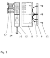
- a laser beam 1 between two optical elements 2 and 3 must be adjusted.
- the laser beam 1 should be adjusted by means of adjustment options on the optical element 3 (rotation axis 4 and 5) , so that the laser beam 1 hits the center of the optical element 2.
- a device 6 for determining the position of the incident laser beam 1 is detachably attached to the optical element 2.
- the device 6 for determining the position of the laser beam 1 has radially arranged light guides 7 .
- the inner ends of the four light guides 7 are arranged at a regular pitch on a circle which is concentric with the center of a circular support plate 8 .
- the outer ends of the optical fibers 7 as visualization means (scattering surface for the laser beam) are mounted on a turn concentric circle with a larger diameter.
- the ends of the light guides 7 are fixed in through holes of the support plate 8 so that they are inserted through the support plate 8 and terminate flush on the surface 9 .
- a light guide 10 In the center of the support plate 8, the one end of a light guide 10 (see FIGS. 4 and 5) is positioned, whose outer end terminates at a position on the support plate 8, which lies outside of the spanned by the outer ends of the light guide 1 cross.
- the ends of this light guide 10 are also inserted through through holes through the plate and secured therein flush with the surface 9.
- the support plate 8 is positively in a cylindrical recess which is fixed concentrically to a cylindrical housing 11 at one end face by means of screws 12 .
- the depth of the countersink is chosen to ensure safe centering.
- the housing 11 has on the side of the first countersinking a further deeper countersinking of smaller diameter. The diameter and the depth are chosen so that they ensure the required installation space for the light guides 1 and 10.
- the housing 11 is connected with screws 13 and at least two cylindrical pins 14 with a fastening ring 15 .
- the mounting ring 15 has an outer diameter which corresponds approximately to the outer diameter of the housing 11, and an inner diameter which is adapted to the diameter of a mounting flange at the end of the beam path.
- the mounting ring 15 is radially interrupted at a position with a defined gap width and has at this point on one side tangentially a bore with a cylinder counterbore and on the other side tangentially a thread with a corresponding thread diameter.
- the cross-section of the ring 15 is only partially interrupted, and the material is continuously present at the outer diameter with a wall thickness which corresponds approximately to half of the cross-sectional area.
- the ring 15 can be slightly widened due to the interruptions and then clamped by means of a screw 16 on the mounting flange at the end of the beam path.
- the attachment of the housing 11 by means of screws and cylindrical pins on the ring portion on the same side of the column ensures the most accurate centric mounting of the device for determining the position of the laser beam.
- the light guide 10 absorbs most of the radiation and its outer end lights up most intensely. If the laser beam 1 is not adjusted, one of the light guides 7 absorbs most of the radiation and its outer end lights up most intensely. From the view of the front of the support plate 8 of FIG. 4 , the user can easily control the adjustment and perform.
- the arrangement of the light guides 7 and 10 on the back of the support plate 8 can be seen in FIG. 5 .
Landscapes
- Physics & Mathematics (AREA)
- Optics & Photonics (AREA)
- Engineering & Computer Science (AREA)
- Plasma & Fusion (AREA)
- Mechanical Engineering (AREA)
- Photometry And Measurement Of Optical Pulse Characteristics (AREA)
Priority Applications (1)
| Application Number | Priority Date | Filing Date | Title |
|---|---|---|---|
| EP04025297A EP1649964A1 (fr) | 2004-10-25 | 2004-10-25 | Dispositif de détermination de la position d'un rayon laser |
Applications Claiming Priority (1)
| Application Number | Priority Date | Filing Date | Title |
|---|---|---|---|
| EP04025297A EP1649964A1 (fr) | 2004-10-25 | 2004-10-25 | Dispositif de détermination de la position d'un rayon laser |
Publications (1)
| Publication Number | Publication Date |
|---|---|
| EP1649964A1 true EP1649964A1 (fr) | 2006-04-26 |
Family
ID=34927094
Family Applications (1)
| Application Number | Title | Priority Date | Filing Date |
|---|---|---|---|
| EP04025297A Withdrawn EP1649964A1 (fr) | 2004-10-25 | 2004-10-25 | Dispositif de détermination de la position d'un rayon laser |
Country Status (1)
| Country | Link |
|---|---|
| EP (1) | EP1649964A1 (fr) |
Citations (5)
| Publication number | Priority date | Publication date | Assignee | Title |
|---|---|---|---|---|
| GB2184831A (en) * | 1985-12-20 | 1987-07-01 | Atomic Energy Authority Uk | Radiation beam position sensor |
| US4918284A (en) * | 1988-10-14 | 1990-04-17 | Teradyne Laser Systems, Inc. | Calibrating laser trimming apparatus |
| US5166505A (en) * | 1990-04-24 | 1992-11-24 | Messerschmitt-Bolkow-Blohm Gmbh | Measuring process and arrangement for the three-dimensional position control of the focal point of high-energy laser beam |
| US5939704A (en) * | 1994-04-05 | 1999-08-17 | British Nuclear Fuels Plc | Radiation beam position sensor |
| DE10222786A1 (de) * | 2002-05-23 | 2003-11-20 | Bosch Gmbh Robert | Verfahren zur Positionierung von Werkstücken bei Laserbearbeitungsprozessen |
-
2004
- 2004-10-25 EP EP04025297A patent/EP1649964A1/fr not_active Withdrawn
Patent Citations (5)
| Publication number | Priority date | Publication date | Assignee | Title |
|---|---|---|---|---|
| GB2184831A (en) * | 1985-12-20 | 1987-07-01 | Atomic Energy Authority Uk | Radiation beam position sensor |
| US4918284A (en) * | 1988-10-14 | 1990-04-17 | Teradyne Laser Systems, Inc. | Calibrating laser trimming apparatus |
| US5166505A (en) * | 1990-04-24 | 1992-11-24 | Messerschmitt-Bolkow-Blohm Gmbh | Measuring process and arrangement for the three-dimensional position control of the focal point of high-energy laser beam |
| US5939704A (en) * | 1994-04-05 | 1999-08-17 | British Nuclear Fuels Plc | Radiation beam position sensor |
| DE10222786A1 (de) * | 2002-05-23 | 2003-11-20 | Bosch Gmbh Robert | Verfahren zur Positionierung von Werkstücken bei Laserbearbeitungsprozessen |
Similar Documents
| Publication | Publication Date | Title |
|---|---|---|
| DE102007063627B4 (de) | Verfahren zur Bestimmung der Lage eines Laserstrahls relativ zu einer Öffnung, sowie Laserbearbeitungsmaschine | |
| DE4328671B4 (de) | Streulichtrauchmelder | |
| DE19654276A1 (de) | Vorrichtung zur berührungslosen Temperaturmessung | |
| EP3490752B1 (fr) | Ensemble broche pour une machine-outil comprenant un élément optique ainsi qu'élément optique, en particulier pour un ensemble broche de ce type | |
| DE68922181T2 (de) | Optisches Transmissionsspektrometer. | |
| EP2855930B1 (fr) | Procédé d'installation de capteurs dans des pales de rotor et dispositif d'installation | |
| DE3441429C2 (fr) | ||
| EP0421135A2 (fr) | Méthode et procédé pour la détermination de la position et du diamètre de la tache focale d'un rayon laser, en particulier pour l'usinage de matériaux avec un laser haute puissance | |
| DE3615874A1 (de) | Verfahren zur messung der entfernung einer handwerkzeugmaschine von einem werkstueck | |
| EP1750891B1 (fr) | Procede de determination de la position focale d'un faisceau laser | |
| EP4526662B1 (fr) | Système de spectromètre pour l'analyse spectrale du plasma induite par laser | |
| DE2837743C3 (de) | Opto-elektronischer Positionsgeber | |
| EP1649964A1 (fr) | Dispositif de détermination de la position d'un rayon laser | |
| DE10335207A1 (de) | Visiereinrichtung und Vorrichtung mit einer kontaktlos oder kontaktbehaftet einsetzbaren Mess-, Arbeits- und/oder Wirkeinrichtung | |
| DE102012021891B4 (de) | Sensor, insbesondere optischer Sensor | |
| DE3919067A1 (de) | Verfahren und vorrichtung zur herstellung eines lichtwellenleiters | |
| EP3278060B1 (fr) | Procédé servant à disposer un système d'alignement à laser sur un dispositif comprenant deux arbres reliés l'un à l'autre par un couplage | |
| DE4005453A1 (de) | Einrichtung zur abstandsmessung bei der laser-materialbearbeitung | |
| DE102010015641B4 (de) | Spektrometer | |
| DE10041692A1 (de) | Längen- oder Winkelmeßgerät | |
| DE69705656T2 (de) | Verfahren und Vorrichtung für die Aufgabe von Material an Wachstum auf einer Oberfläche | |
| DE102007032249B3 (de) | Tastendes Lichtgitter | |
| DE102010000973B4 (de) | Handwerkzeug mit Projektionselement sowie Projektionselement | |
| DE19830473C1 (de) | Vorrichtung zum Erzeugen und Erfassen von induzierter Wärmestrahlung | |
| DE19837152A1 (de) | Medizinisches Therapie- und/oder Diagnosegerät mit einer Positionserfassungseinrichtung |
Legal Events
| Date | Code | Title | Description |
|---|---|---|---|
| PUAI | Public reference made under article 153(3) epc to a published international application that has entered the european phase |
Free format text: ORIGINAL CODE: 0009012 |
|
| 17P | Request for examination filed |
Effective date: 20050916 |
|
| AK | Designated contracting states |
Kind code of ref document: A1 Designated state(s): AT BE BG CH CY CZ DE DK EE ES FI FR GB GR HU IE IT LI LU MC NL PL PT RO SE SI SK TR |
|
| AX | Request for extension of the european patent |
Extension state: AL HR LT LV MK |
|
| AKX | Designation fees paid |
Designated state(s): AT BE BG CH CY CZ DE DK EE ES FI FR GB GR HU IE IT LI LU MC NL PL PT RO SE SI SK TR |
|
| 17Q | First examination report despatched |
Effective date: 20070912 |
|
| STAA | Information on the status of an ep patent application or granted ep patent |
Free format text: STATUS: THE APPLICATION IS DEEMED TO BE WITHDRAWN |
|
| 18D | Application deemed to be withdrawn |
Effective date: 20090421 |