EP1649966A1 - Düse für einen Laserbohrkopf - Google Patents
Düse für einen Laserbohrkopf Download PDFInfo
- Publication number
- EP1649966A1 EP1649966A1 EP05109916A EP05109916A EP1649966A1 EP 1649966 A1 EP1649966 A1 EP 1649966A1 EP 05109916 A EP05109916 A EP 05109916A EP 05109916 A EP05109916 A EP 05109916A EP 1649966 A1 EP1649966 A1 EP 1649966A1
- Authority
- EP
- European Patent Office
- Prior art keywords
- nozzle
- laser beam
- mirror
- drilling
- blades
- Prior art date
- Legal status (The legal status is an assumption and is not a legal conclusion. Google has not performed a legal analysis and makes no representation as to the accuracy of the status listed.)
- Granted
Links
Images
Classifications
-
- B—PERFORMING OPERATIONS; TRANSPORTING
- B23—MACHINE TOOLS; METAL-WORKING NOT OTHERWISE PROVIDED FOR
- B23K—SOLDERING OR UNSOLDERING; WELDING; CLADDING OR PLATING BY SOLDERING OR WELDING; CUTTING BY APPLYING HEAT LOCALLY, e.g. FLAME CUTTING; WORKING BY LASER BEAM
- B23K26/00—Working by laser beam, e.g. welding, cutting or boring
- B23K26/36—Removing material
- B23K26/38—Removing material by boring or cutting
- B23K26/382—Removing material by boring or cutting by boring
-
- B—PERFORMING OPERATIONS; TRANSPORTING
- B23—MACHINE TOOLS; METAL-WORKING NOT OTHERWISE PROVIDED FOR
- B23K—SOLDERING OR UNSOLDERING; WELDING; CLADDING OR PLATING BY SOLDERING OR WELDING; CUTTING BY APPLYING HEAT LOCALLY, e.g. FLAME CUTTING; WORKING BY LASER BEAM
- B23K26/00—Working by laser beam, e.g. welding, cutting or boring
- B23K26/02—Positioning or observing the workpiece, e.g. with respect to the point of impact; Aligning, aiming or focusing the laser beam
- B23K26/06—Shaping the laser beam, e.g. by masks or multi-focusing
- B23K26/064—Shaping the laser beam, e.g. by masks or multi-focusing by means of optical elements, e.g. lenses, mirrors or prisms
- B23K26/0643—Shaping the laser beam, e.g. by masks or multi-focusing by means of optical elements, e.g. lenses, mirrors or prisms comprising mirrors
-
- B—PERFORMING OPERATIONS; TRANSPORTING
- B23—MACHINE TOOLS; METAL-WORKING NOT OTHERWISE PROVIDED FOR
- B23K—SOLDERING OR UNSOLDERING; WELDING; CLADDING OR PLATING BY SOLDERING OR WELDING; CUTTING BY APPLYING HEAT LOCALLY, e.g. FLAME CUTTING; WORKING BY LASER BEAM
- B23K26/00—Working by laser beam, e.g. welding, cutting or boring
- B23K26/08—Devices involving relative movement between laser beam and workpiece
- B23K26/10—Devices involving relative movement between laser beam and workpiece using a fixed support, i.e. involving moving the laser beam
- B23K26/103—Devices involving relative movement between laser beam and workpiece using a fixed support, i.e. involving moving the laser beam the laser beam rotating around the fixed workpiece
- B23K26/106—Devices involving relative movement between laser beam and workpiece using a fixed support, i.e. involving moving the laser beam the laser beam rotating around the fixed workpiece inside the workpiece
-
- B—PERFORMING OPERATIONS; TRANSPORTING
- B23—MACHINE TOOLS; METAL-WORKING NOT OTHERWISE PROVIDED FOR
- B23K—SOLDERING OR UNSOLDERING; WELDING; CLADDING OR PLATING BY SOLDERING OR WELDING; CUTTING BY APPLYING HEAT LOCALLY, e.g. FLAME CUTTING; WORKING BY LASER BEAM
- B23K26/00—Working by laser beam, e.g. welding, cutting or boring
- B23K26/14—Working by laser beam, e.g. welding, cutting or boring using a fluid stream, e.g. a jet of gas, in conjunction with the laser beam; Nozzles therefor
- B23K26/142—Working by laser beam, e.g. welding, cutting or boring using a fluid stream, e.g. a jet of gas, in conjunction with the laser beam; Nozzles therefor for the removal of by-products
-
- B—PERFORMING OPERATIONS; TRANSPORTING
- B23—MACHINE TOOLS; METAL-WORKING NOT OTHERWISE PROVIDED FOR
- B23K—SOLDERING OR UNSOLDERING; WELDING; CLADDING OR PLATING BY SOLDERING OR WELDING; CUTTING BY APPLYING HEAT LOCALLY, e.g. FLAME CUTTING; WORKING BY LASER BEAM
- B23K26/00—Working by laser beam, e.g. welding, cutting or boring
- B23K26/14—Working by laser beam, e.g. welding, cutting or boring using a fluid stream, e.g. a jet of gas, in conjunction with the laser beam; Nozzles therefor
- B23K26/1462—Nozzles; Features related to nozzles
- B23K26/1488—Means for protecting nozzles, e.g. the tip surface
-
- B—PERFORMING OPERATIONS; TRANSPORTING
- B23—MACHINE TOOLS; METAL-WORKING NOT OTHERWISE PROVIDED FOR
- B23K—SOLDERING OR UNSOLDERING; WELDING; CLADDING OR PLATING BY SOLDERING OR WELDING; CUTTING BY APPLYING HEAT LOCALLY, e.g. FLAME CUTTING; WORKING BY LASER BEAM
- B23K26/00—Working by laser beam, e.g. welding, cutting or boring
- B23K26/36—Removing material
- B23K26/38—Removing material by boring or cutting
- B23K26/382—Removing material by boring or cutting by boring
- B23K26/389—Removing material by boring or cutting by boring of fluid openings, e.g. nozzles, jets
-
- B—PERFORMING OPERATIONS; TRANSPORTING
- B23—MACHINE TOOLS; METAL-WORKING NOT OTHERWISE PROVIDED FOR
- B23K—SOLDERING OR UNSOLDERING; WELDING; CLADDING OR PLATING BY SOLDERING OR WELDING; CUTTING BY APPLYING HEAT LOCALLY, e.g. FLAME CUTTING; WORKING BY LASER BEAM
- B23K26/00—Working by laser beam, e.g. welding, cutting or boring
- B23K26/36—Removing material
- B23K26/40—Removing material taking account of the properties of the material involved
-
- B—PERFORMING OPERATIONS; TRANSPORTING
- B23—MACHINE TOOLS; METAL-WORKING NOT OTHERWISE PROVIDED FOR
- B23K—SOLDERING OR UNSOLDERING; WELDING; CLADDING OR PLATING BY SOLDERING OR WELDING; CUTTING BY APPLYING HEAT LOCALLY, e.g. FLAME CUTTING; WORKING BY LASER BEAM
- B23K2101/00—Articles made by soldering, welding or cutting
- B23K2101/001—Turbines
-
- B—PERFORMING OPERATIONS; TRANSPORTING
- B23—MACHINE TOOLS; METAL-WORKING NOT OTHERWISE PROVIDED FOR
- B23K—SOLDERING OR UNSOLDERING; WELDING; CLADDING OR PLATING BY SOLDERING OR WELDING; CUTTING BY APPLYING HEAT LOCALLY, e.g. FLAME CUTTING; WORKING BY LASER BEAM
- B23K2103/00—Materials to be soldered, welded or cut
- B23K2103/18—Dissimilar materials
- B23K2103/26—Alloys of Nickel and Cobalt and Chromium
Definitions
- the present invention relates to the drilling of metallic or non-metallic parts by means of a laser beam.
- It relates in particular to a nozzle for a laser beam drilling head of a laser beam machining apparatus used in particular for drilling holes in a metal wall or not, inaccessible or difficult to access to the laser beam drilling tools of the prior art.
- the YAG-Nd type pulsed laser beam technique is commonly used to drill small diameter orifices in the wall of certain engine parts comprising a turbine or a compressor. These are, for example, parts subjected to high temperatures such as turbine blades or distributor fins in the high-pressure part of the machine or even wall elements of the combustion chamber of the engine. These holes have the function of allowing the flow of air streams from inside the room, which provide cooling and thermal protection.
- a pulsed laser beam of appropriate energy is directed against the wall by focusing it on the zone to be pierced.
- the material is then raised to a high temperature locally causing its melting and partly its vaporization.
- the molten material is expelled by the assisting fluid that is injected into the axis of the beam; it leaves an orifice in the wall.
- generally cylindrical orifices with a diameter ranging from 0.2 mm to 1.5 mm for a depth of 0.8 to 20 mm, and holes of various shapes: diamond, shape holes, etc., are commonly drilled.
- the materials concerned in the field of gas turbine engines are mainly nickel-based or cobalt-based alloys, possibly with a coating forming a thermal barrier. However all materials are concerned.
- a YAG Nd type pulsed laser beam used in this field of application produces, according to one example, an energy of 4 Joules at a frequency of 30 Hz with a pulse duration of 1.2 ms and a peak power of 3. 3 kW for an average power of 120 W.
- the laser beam machining apparatuses currently used comprise a machining head of substantially tubular or frustoconical shape comprising an optical system, comprising at least one beam focusing lens, through which the emitted beam is concentrated in a denser beam to a distance determined by the focal length of the optics.
- the head ends with a straight nozzle through which the beam also forms an injection nozzle for the assist fluid, for example gaseous.
- the beam is placed at a given angle relative to the surface of the area to be treated, for drilling holes. Because of the structure of the machining head and its geometry, sufficient space must therefore be available in the axis of the hole to be drilled in the wall to be able to place the tool. This space in the current technology is at least that between the focusing point (piercing zone) and the focusing lens, ie a large size greatly limiting the possibilities of access to the holes
- the applicant company has therefore set itself the goal of creating a nozzle allowing access to areas with poor accessibility.
- this objective is achieved with a laser beam drilling head nozzle, for a drilling machine, emitting a pulsed laser beam, the piercing head comprising a means suitable for mounting the nozzle, the nozzle comprising a first laser beam input aperture and a second pulsed laser beam output aperture, a beam focusing means being provided upstream of the second aperture.
- This nozzle is characterized in that a mirror is placed on the optical path of the laser beam downstream of said collimating means, so that the outgoing beam forms an angle less than 180 ° with the incoming beam, the nozzle comprising a feed a laser beam assist fluid arranged such that said fluid is emitted from the second aperture in the direction of the laser beam.
- a nozzle that can be strongly inclined relative to the surface of the workpiece, depending on the space available above the surface and in the axis of the hole to be drilled.
- a nozzle according to the invention allowing the production of holes in previously inaccessible areas, opens the possibility of achieving significant gains in cooling efficiency.
- Such a nozzle also makes it possible to optimize the manufacturing methods and to open the design possibilities of certain parts insofar as these are not related to the need to provide accessibility by means of drilling.
- the assisting fluid is advantageously a gas whose function is not only to participate in the evacuation of the slag produced by the beam but also to cool the mirror which is subjected to the impact of the focused laser beam and to assist to the melting and evacuation of the particles if necessary.
- Laser beam welding heads are already known with an end nozzle having a beam deflection mirror at 90 °.
- the applicant holds a patent, EP 1 273 382, relating to a miniaturized laser beam welding apparatus.
- the subject of this patent relates to a welding head whose front opening can be brought very close to the surface to be welded without the optical components being smeared by the vapors and projections of molten metal and without this molten metal. is disturbed by the flow of gas leaving the front opening.
- this type of tool is designed to come in the extension of an optical fiber and comprises a suitable optical system including collimation lens and focusing lens. Even if it is said to be miniaturized, there remains a large size compared to the application envisaged in the present invention.
- the lasers used for welding are continuous CO 2 gas equipment unlike machining lasers which are characterized by pulse mode operation with a determined peak power. The teaching of this patent is not appropriate for an application to the machining of metal parts.
- the mirror is held by a removable fastening means which makes it possible to quickly replace the mirror after a series of shots, without having to change the nozzle.
- the second opening of the nozzle is provided with a means of protection against the projection of slag by the part in treatment.
- This means of protection which is for example a blade, prevents the return mirror from being stained by the slag.
- such a nozzle is used for drilling cooling orifices on the blades of a gas turbine engine distributor element, in particular an aeronautical, consisting of at least two blades.
- a complete wheel such as a monobloc disk.
- the diameter is then adapted to allow positioning between the blades of a gas turbine engine turbine high pressure distributor sector.
- the focal point of the beam is distant from the mirror by a distance of less than 15 mm.
- this distance allows a sufficient miniaturization of the nozzle relative to the available space between the blades of the block for optimal access in all points of the intrados and extrados surfaces.
- This distance very low, allows very great accessibility for all other types of room, such as combustion chamber rings for example or any other application requiring holes not accessible with the right nozzle technology in the prior art.
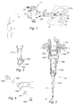
- FIG. 1 shows an exemplary embodiment of a laser beam drilling device according to the invention. Only the essential elements are reproduced. They are here in position for the drilling of valve blades.
- the laser source 1 is, for example, of YAG-Nd type pulsed at a wavelength of 1064 ⁇ m; a laser beam 2 is transmitted by the apparatus to the machining head 3.
- This head comprises an input 31 of assist fluid and a tubular portion 32 along the optical path C of the beam.
- the optical system 33 beam focusing. It is a lens whose focal length determines the point of focus of the beam downstream thereof.
- a nozzle 4 made of metal, for example, is removably attached to the downstream end of the head 3 in the extension of the optical path of the laser beam.
- the nozzle comprises a first opening 41 for entering the laser beam coming from the tubular portion of the head 3, and a second opening 42 for outputting the beam.
- the output 42 is lateral.
- a reflecting mirror 5 is disposed across the optical path C with an angle of 45 ° here and thus deflects the beam at 90 °.
- the converging laser beam concentrates at a point at a distance from the reflecting mirror, called the focusing point.
- This nozzle 4 according to the invention is mounted on the head 3 to replace a straight nozzle of the prior art. In this embodiment, the head 3 and the entire device therefore do not require modification. Only the nozzle 4 is new.
- the reflecting mirror intercepting the beam after focusing, the reflected energy density is very important.
- the factors to be considered regarding the mirror are in particular its limit of resistance and its lifetime.
- the first is determined by the energy density of the laser and the second by the peak power.
- the high-flux mirrors consist of a substrate and a treatment according to the wavelength used.
- Two examples of materials for forming the substrate are fused silica and borosilicate glass (BK7). They have a flow resistance of 73J / cm 2 for BK7 and 75 J / cm 2 for silica molten.
- the treatments consist of dielectric layers that determine the wavelength and angle of incidence of the mirror.
- the part 71, respectively 72 is a blade of a gas turbine engine distributor block 8, consisting of two blades 71 and 72. Thanks to the device of the invention, it is it is not necessary to separate the two blades.
- the nozzle 4 at the end of the head 3 can slide into the space provided between the two blades of the block, and come to pierce the orifices both along the extrados of the blade 71 and along the lower surface of the blade. adjacent blade 72.
- the diameter of the nozzle is for example 10 mm near its end. It can be set up in a space as small as 20 mm.
- FIG. 2 a second embodiment of the nozzle.
- the head 13 comprises a plate 131 with a focusing lens 132 protected by a blade 133.
- the assembly is covered with a shell 134 extended by a support 135 for the nozzle 14.
- the nozzle 14 is mounted on the support 135 by a external coupling member 140.
- the body of the nozzle itself consists of cylindrical portions 141 of decreasing diameters towards its end.
- FIG. 3 shows the end of the nozzle in more detail, and Figure 4 the different parts that it comprises an exploded representation.
- the nozzle is pierced in the extension of its tubular portion and comprises a housing 142 for a mirror 145.
- the mirror is held in its housing by a clip 146 consisting of a ring and two branches with hooks which are housed in notches formed in the tube.
- the ring allows the portion of the beam transmitted and not reflected by the mirror not to be absorbed by the nozzle.
- the mirror is placed in the housing to form a predetermined angle with the optical path of the laser beam.
- the nozzle In the direction formed by the optical path after its reflection on the mirror 145, the nozzle comprises a tube portion 143 which terminates in a transverse housing 144 for a protection blade 147 disposed transversely to the optical path; the blade 147 is held by an injector part 148 and having a screw thread.
- a channel not visible in the figures places the inside of the tube 141 in communication with the injector 148.
- the laser beam is focused by the lens 132 and reflected by the mirror 145; the beam density is maximum at the focal point located downstream of the injector 148.
- An assisting fluid is introduced under pressure into the nozzle, coaxially with the beam and is injected in the direction of the outgoing beam by the injector 148 This fluid contributes to the cooling of the mirror by sweeping its surface.
- the protection blade prevents slag ejected from the treatment area from smearing the mirror.
- the angle that the beam exiting through the second opening of the nozzle with the incident beam is determined by the geometry of the workpiece.
- the angle is 45 °, it can be different.
- it is less than 85 °, for example between 30 ° and 80 °.
- the focal length can be lengthened by using a suitable focusing lens.
- the mirror 145 is concave type.
- a complementary lens focusing is placed downstream of the mirror 145 a complementary lens focusing.
- Drilling tests were carried out on a block consisting of two blades assembled between two platforms for a cooled single-crystal or equiaxed high-pressure distributor of a gas turbine engine.
- the nozzle and in particular its end supporting the mirror, was sufficiently miniaturized to have access to the majority of the two surfaces intrados and extrados vis-à-vis.
- the laser source used was pulsed YAG Nd type having the characteristics of that presented above.
Landscapes
- Physics & Mathematics (AREA)
- Optics & Photonics (AREA)
- Engineering & Computer Science (AREA)
- Plasma & Fusion (AREA)
- Mechanical Engineering (AREA)
- Laser Beam Processing (AREA)
- Turbine Rotor Nozzle Sealing (AREA)
Applications Claiming Priority (1)
| Application Number | Priority Date | Filing Date | Title |
|---|---|---|---|
| FR0452437A FR2876933B1 (fr) | 2004-10-25 | 2004-10-25 | Buse pour tete de percage ou d'usinage par faisceau laser |
Publications (2)
| Publication Number | Publication Date |
|---|---|
| EP1649966A1 true EP1649966A1 (de) | 2006-04-26 |
| EP1649966B1 EP1649966B1 (de) | 2011-05-18 |
Family
ID=34950257
Family Applications (1)
| Application Number | Title | Priority Date | Filing Date |
|---|---|---|---|
| EP05109916A Expired - Lifetime EP1649966B1 (de) | 2004-10-25 | 2005-10-24 | Anwendung einer Düse für einen Laserbohrkopf |
Country Status (7)
| Country | Link |
|---|---|
| US (1) | US7671296B2 (de) |
| EP (1) | EP1649966B1 (de) |
| JP (1) | JP2006123005A (de) |
| CN (1) | CN1788917B (de) |
| CA (1) | CA2526328C (de) |
| FR (1) | FR2876933B1 (de) |
| RU (1) | RU2393072C2 (de) |
Cited By (4)
| Publication number | Priority date | Publication date | Assignee | Title |
|---|---|---|---|---|
| EP2065121A1 (de) * | 2007-11-28 | 2009-06-03 | Siemens Aktiengesellschaft | Fokussiervorrichtung mit Umlenkung für elektromagnetische Strahlung |
| EP2206575A1 (de) * | 2009-01-12 | 2010-07-14 | Rolls-Royce Deutschland Ltd & Co KG | Vorrichtung zur Reparatur der Schaufeln von BLISK-Trommeln mittels Laserstrahlauftragsschweißen |
| WO2015108916A1 (en) * | 2014-01-15 | 2015-07-23 | Siemens Energy, Inc. | Apparatus for laser processing of hidden surfaces |
| EP2670564B1 (de) * | 2011-02-04 | 2020-01-08 | Fraunhofer-Gesellschaft zur Förderung der angewandten Forschung e.V. | Werkzeugwechselträger und werkzeugsystem |
Families Citing this family (10)
| Publication number | Priority date | Publication date | Assignee | Title |
|---|---|---|---|---|
| GB2467130B (en) * | 2009-01-22 | 2012-11-28 | Cav Advanced Technologies Ltd | Method for perforating material |
| CN102861935A (zh) * | 2011-07-06 | 2013-01-09 | 邱金和 | 一种切削的方法 |
| FR2991214B1 (fr) * | 2012-06-01 | 2014-06-13 | Snecma | Procede de percage d'une piece par impulsions laser |
| TWI508810B (zh) * | 2013-12-13 | 2015-11-21 | Metal Ind Res & Dev Ct | 雷射輔助加工裝置 |
| DE102017200080A1 (de) * | 2017-01-05 | 2018-07-05 | Volkswagen Aktiengesellschaft | Laserwerkzeug mit Hohlwellenantrieb und nicht-rotierender Linse |
| CN109202307A (zh) * | 2017-11-24 | 2019-01-15 | 中国航空制造技术研究院 | 一种激光制孔装置 |
| US11273520B2 (en) * | 2019-01-31 | 2022-03-15 | General Electric Company | System and method for automated laser ablation |
| WO2021014516A1 (ja) * | 2019-07-19 | 2021-01-28 | ヤマザキマザック株式会社 | レーザ加工機、及び、レーザ加工機の保守方法 |
| CN110497545B (zh) * | 2019-08-13 | 2021-06-08 | 安徽晶天新能源科技有限责任公司 | 一种太阳能硅片生产加工工艺 |
| CN112496616B (zh) * | 2020-11-20 | 2022-06-21 | 安徽铭大汽车科技有限公司 | 一种自动化汽车防撞梁焊接熔孔设备 |
Citations (5)
| Publication number | Priority date | Publication date | Assignee | Title |
|---|---|---|---|---|
| US5083006A (en) * | 1990-03-02 | 1992-01-21 | Rolls-Royce Plc | Laser drilling of components |
| EP0876870A1 (de) * | 1997-04-21 | 1998-11-11 | Automobiles Peugeot | Vorrichtung und Verfahren zum Laserbehandeln der Zylinderinnenfläche einer Brennkraftmaschine |
| EP1127652A1 (de) * | 2000-02-26 | 2001-08-29 | Volkswagen Aktiengesellschaft | Verfahren und Vorrichtung zum Bearbeiten einer Innenfläche einer zylinderförmigen Bohrung mittels Laser und gekühlter Umlenkoptik |
| EP1273382A1 (de) | 2001-07-05 | 2003-01-08 | Snecma Moteurs | Schweissvorrichtung mit einem miniturisierten Laserstrahl |
| FR2850892A1 (fr) * | 2003-02-06 | 2004-08-13 | Process Conception Ing Sa | Dispositif de striation sectorielle non lineaire par laser a commande numerique et procede de striation associe, pieces striees obtenues a l'aide de ce dispositif |
Family Cites Families (16)
| Publication number | Priority date | Publication date | Assignee | Title |
|---|---|---|---|---|
| FR2516597A1 (fr) * | 1981-11-16 | 1983-05-20 | Snecma | Dispositif annulaire de joint d'usure et d'etancheite refroidi par l'air pour aubage de roue de turbine a gaz ou de compresseur |
| SU1472200A1 (ru) * | 1984-05-11 | 1989-04-15 | Научно-исследовательский центр по технологическим лазерам АН СССР | Установка дл лазерной обработки |
| EP0300458B1 (de) * | 1987-07-21 | 1991-12-18 | Mitsubishi Jukogyo Kabushiki Kaisha | Laserstrahlschweissverfahren für eine Innenumfangsfläche eines Rohres |
| DE59002985D1 (de) * | 1989-07-14 | 1993-11-11 | Maho Ag | Verfahren und Vorrichtung zum Herstellen von Hohlräumen in Werkstücken mittels Laserstrahls. |
| JP2619737B2 (ja) * | 1990-09-28 | 1997-06-11 | 三菱電機株式会社 | レ−ザ加工装置 |
| FR2683896B1 (fr) | 1991-11-15 | 1996-05-15 | Etia | Appareil pour le traitement thermique a haute temperature d'un corps solide divise. |
| JP3282316B2 (ja) * | 1993-10-25 | 2002-05-13 | 石川島播磨重工業株式会社 | レーザー照射装置 |
| US5645740A (en) * | 1993-11-01 | 1997-07-08 | Naiman; Charles S. | System and assemblage for producing microtexturized substrates and implants |
| JPH07290261A (ja) * | 1994-04-26 | 1995-11-07 | Nakata Seisakusho:Kk | 自動造管機の溶接方法 |
| NZ272635A (en) * | 1994-08-02 | 1998-02-26 | Mcneil Ppc Inc | Laser cutting/drilling processing head that creates a vortex gas flow within the head to clean and prevent back spatting of particles onto the lens therein |
| JPH1190664A (ja) * | 1997-09-17 | 1999-04-06 | Mitsubishi Heavy Ind Ltd | レーザ加工ヘッド |
| JP4155489B2 (ja) * | 2000-09-28 | 2008-09-24 | 株式会社東芝 | 水中レーザ補修溶接装置 |
| ITTO20010102A1 (it) * | 2001-02-05 | 2002-08-05 | Prima Ind Spa | Sistema e metodo di saldatura laser remota. |
| US6380512B1 (en) * | 2001-10-09 | 2002-04-30 | Chromalloy Gas Turbine Corporation | Method for removing coating material from a cooling hole of a gas turbine engine component |
| FR2860741B1 (fr) * | 2003-10-10 | 2007-04-13 | Snecma Moteurs | Procede de reparation de pieces metalliques notamment d'aubes de turbine de moteur a turbine a gaz |
| US7259353B2 (en) * | 2004-09-30 | 2007-08-21 | Honeywell International, Inc. | Compact coaxial nozzle for laser cladding |
-
2004
- 2004-10-25 FR FR0452437A patent/FR2876933B1/fr not_active Expired - Lifetime
-
2005
- 2005-10-24 CA CA2526328A patent/CA2526328C/fr not_active Expired - Lifetime
- 2005-10-24 EP EP05109916A patent/EP1649966B1/de not_active Expired - Lifetime
- 2005-10-25 CN CN2005101182811A patent/CN1788917B/zh not_active Expired - Lifetime
- 2005-10-25 JP JP2005310091A patent/JP2006123005A/ja active Pending
- 2005-10-25 RU RU2005132920/02A patent/RU2393072C2/ru active
- 2005-10-25 US US11/257,002 patent/US7671296B2/en active Active
Patent Citations (5)
| Publication number | Priority date | Publication date | Assignee | Title |
|---|---|---|---|---|
| US5083006A (en) * | 1990-03-02 | 1992-01-21 | Rolls-Royce Plc | Laser drilling of components |
| EP0876870A1 (de) * | 1997-04-21 | 1998-11-11 | Automobiles Peugeot | Vorrichtung und Verfahren zum Laserbehandeln der Zylinderinnenfläche einer Brennkraftmaschine |
| EP1127652A1 (de) * | 2000-02-26 | 2001-08-29 | Volkswagen Aktiengesellschaft | Verfahren und Vorrichtung zum Bearbeiten einer Innenfläche einer zylinderförmigen Bohrung mittels Laser und gekühlter Umlenkoptik |
| EP1273382A1 (de) | 2001-07-05 | 2003-01-08 | Snecma Moteurs | Schweissvorrichtung mit einem miniturisierten Laserstrahl |
| FR2850892A1 (fr) * | 2003-02-06 | 2004-08-13 | Process Conception Ing Sa | Dispositif de striation sectorielle non lineaire par laser a commande numerique et procede de striation associe, pieces striees obtenues a l'aide de ce dispositif |
Non-Patent Citations (1)
| Title |
|---|
| VANDERWERT T L ET AL: "LASER DRILLING EFFUSION COOLING HOLES IN LOW NOX TURBINE ENGINE COMPONENTS", ASME TURBO ASIA CONFERENCE, XX, XX, November 1996 (1996-11-01), pages 1 - 8, XP002925532 * |
Cited By (4)
| Publication number | Priority date | Publication date | Assignee | Title |
|---|---|---|---|---|
| EP2065121A1 (de) * | 2007-11-28 | 2009-06-03 | Siemens Aktiengesellschaft | Fokussiervorrichtung mit Umlenkung für elektromagnetische Strahlung |
| EP2206575A1 (de) * | 2009-01-12 | 2010-07-14 | Rolls-Royce Deutschland Ltd & Co KG | Vorrichtung zur Reparatur der Schaufeln von BLISK-Trommeln mittels Laserstrahlauftragsschweißen |
| EP2670564B1 (de) * | 2011-02-04 | 2020-01-08 | Fraunhofer-Gesellschaft zur Förderung der angewandten Forschung e.V. | Werkzeugwechselträger und werkzeugsystem |
| WO2015108916A1 (en) * | 2014-01-15 | 2015-07-23 | Siemens Energy, Inc. | Apparatus for laser processing of hidden surfaces |
Also Published As
| Publication number | Publication date |
|---|---|
| JP2006123005A (ja) | 2006-05-18 |
| FR2876933A1 (fr) | 2006-04-28 |
| RU2005132920A (ru) | 2007-04-27 |
| CA2526328A1 (fr) | 2006-04-25 |
| CN1788917B (zh) | 2010-11-03 |
| RU2393072C2 (ru) | 2010-06-27 |
| FR2876933B1 (fr) | 2008-05-09 |
| CA2526328C (fr) | 2013-02-12 |
| EP1649966B1 (de) | 2011-05-18 |
| CN1788917A (zh) | 2006-06-21 |
| US7671296B2 (en) | 2010-03-02 |
| US20060096965A1 (en) | 2006-05-11 |
Similar Documents
| Publication | Publication Date | Title |
|---|---|---|
| EP1649966B1 (de) | Anwendung einer Düse für einen Laserbohrkopf | |
| EP1931496B1 (de) | Verfahren und installation für laserschneiden/-schweissen | |
| CA2835968C (fr) | Buse laser a element mobile | |
| EP1927426B1 (de) | Verfahren zum Laserbohren eines Werkstücks aus einem Verbundwerkstoff mit einer keramischen Matrix | |
| EP1818130B1 (de) | Verfahren zum Schneiden einer Öffnung in einer metallischen Platte mit einem Laserstrahl mit Hilfe einer eine Öffnung aufweisenden Schutzplatte | |
| EP2390046A1 (de) | Anlage zur Laserbearbeitung mit optischen Fasern zum Eingravieren von Kerben als Bruchansätze | |
| FR2978070A1 (fr) | Procede de reparation d'une piece de turbomachine | |
| WO2003004214A1 (fr) | Appareil de soudage par faisceau laser miniaturise | |
| WO2014072611A1 (fr) | Buse laser avec élément mobile interne et coiffe externe | |
| EP2776206B1 (de) | Laserdüse mit einem auf einer gasschicht beweglichen element | |
| CA2640219C (fr) | Procede de retouche de pieces metalliques | |
| CN113967787A (zh) | 一种激光焊接方法 | |
| FR2766115A1 (fr) | Dispositif et procede de decoupe a distance etendue par laser, en mode impulsionnel | |
| CA2868207A1 (fr) | Buse laser avec element mobile a profil externe ameliore | |
| EP4532939A1 (de) | Verfahren zum zusammenbauen von metallteilen unterschiedlicher grösse und zentrifugaldiffusor hergestellt nach diesem verfahren | |
| EP4017672B1 (de) | Additives fertigungsverfahren für ein teil einer turbomaschine | |
| FR2963749A1 (fr) | Tete de soudage pour laser yag a double soufflage | |
| EP4149714A1 (de) | Laserbeheizung zur herstellung oder reparatur einer turbinenschaufel |
Legal Events
| Date | Code | Title | Description |
|---|---|---|---|
| PUAI | Public reference made under article 153(3) epc to a published international application that has entered the european phase |
Free format text: ORIGINAL CODE: 0009012 |
|
| 17P | Request for examination filed |
Effective date: 20051024 |
|
| AK | Designated contracting states |
Kind code of ref document: A1 Designated state(s): AT BE BG CH CY CZ DE DK EE ES FI FR GB GR HU IE IS IT LI LT LU LV MC NL PL PT RO SE SI SK TR |
|
| AX | Request for extension of the european patent |
Extension state: AL BA HR MK YU |
|
| AKX | Designation fees paid |
Designated state(s): DE FR GB |
|
| GRAP | Despatch of communication of intention to grant a patent |
Free format text: ORIGINAL CODE: EPIDOSNIGR1 |
|
| RTI1 | Title (correction) |
Free format text: USE OF A NOZZLE FOR A LASER DRILLING HEAD |
|
| GRAS | Grant fee paid |
Free format text: ORIGINAL CODE: EPIDOSNIGR3 |
|
| GRAA | (expected) grant |
Free format text: ORIGINAL CODE: 0009210 |
|
| AK | Designated contracting states |
Kind code of ref document: B1 Designated state(s): DE FR GB |
|
| REG | Reference to a national code |
Ref country code: GB Ref legal event code: FG4D Free format text: NOT ENGLISH |
|
| REG | Reference to a national code |
Ref country code: DE Ref legal event code: R096 Ref document number: 602005028078 Country of ref document: DE Effective date: 20110630 |
|
| PLBE | No opposition filed within time limit |
Free format text: ORIGINAL CODE: 0009261 |
|
| STAA | Information on the status of an ep patent application or granted ep patent |
Free format text: STATUS: NO OPPOSITION FILED WITHIN TIME LIMIT |
|
| 26N | No opposition filed |
Effective date: 20120221 |
|
| REG | Reference to a national code |
Ref country code: DE Ref legal event code: R097 Ref document number: 602005028078 Country of ref document: DE Effective date: 20120221 |
|
| REG | Reference to a national code |
Ref country code: FR Ref legal event code: PLFP Year of fee payment: 11 |
|
| REG | Reference to a national code |
Ref country code: FR Ref legal event code: PLFP Year of fee payment: 12 |
|
| REG | Reference to a national code |
Ref country code: FR Ref legal event code: PLFP Year of fee payment: 13 |
|
| REG | Reference to a national code |
Ref country code: FR Ref legal event code: CD Owner name: SAFRAN AIRCRAFT ENGINES, FR Effective date: 20170719 |
|
| REG | Reference to a national code |
Ref country code: FR Ref legal event code: PLFP Year of fee payment: 14 |
|
| PGFP | Annual fee paid to national office [announced via postgrant information from national office to epo] |
Ref country code: GB Payment date: 20240919 Year of fee payment: 20 |
|
| PGFP | Annual fee paid to national office [announced via postgrant information from national office to epo] |
Ref country code: FR Payment date: 20240919 Year of fee payment: 20 |
|
| PGFP | Annual fee paid to national office [announced via postgrant information from national office to epo] |
Ref country code: DE Payment date: 20240919 Year of fee payment: 20 |
|
| REG | Reference to a national code |
Ref country code: DE Ref legal event code: R071 Ref document number: 602005028078 Country of ref document: DE |
|
| REG | Reference to a national code |
Ref country code: GB Ref legal event code: PE20 Expiry date: 20251023 |