EP1649979A2 - Outil de serrage - Google Patents
Outil de serrage Download PDFInfo
- Publication number
- EP1649979A2 EP1649979A2 EP05023028A EP05023028A EP1649979A2 EP 1649979 A2 EP1649979 A2 EP 1649979A2 EP 05023028 A EP05023028 A EP 05023028A EP 05023028 A EP05023028 A EP 05023028A EP 1649979 A2 EP1649979 A2 EP 1649979A2
- Authority
- EP
- European Patent Office
- Prior art keywords
- driving
- side clutch
- clutch element
- clutch
- driven
- Prior art date
- Legal status (The legal status is an assumption and is not a legal conclusion. Google has not performed a legal analysis and makes no representation as to the accuracy of the status listed.)
- Granted
Links
Images




Classifications
-
- B—PERFORMING OPERATIONS; TRANSPORTING
- B25—HAND TOOLS; PORTABLE POWER-DRIVEN TOOLS; MANIPULATORS
- B25F—COMBINATION OR MULTI-PURPOSE TOOLS NOT OTHERWISE PROVIDED FOR; DETAILS OR COMPONENTS OF PORTABLE POWER-DRIVEN TOOLS NOT PARTICULARLY RELATED TO THE OPERATIONS PERFORMED AND NOT OTHERWISE PROVIDED FOR
- B25F5/00—Details or components of portable power-driven tools not particularly related to the operations performed and not otherwise provided for
- B25F5/001—Gearings, speed selectors, clutches or the like specially adapted for rotary tools
-
- B—PERFORMING OPERATIONS; TRANSPORTING
- B25—HAND TOOLS; PORTABLE POWER-DRIVEN TOOLS; MANIPULATORS
- B25B—TOOLS OR BENCH DEVICES NOT OTHERWISE PROVIDED FOR, FOR FASTENING, CONNECTING, DISENGAGING, OR HOLDING
- B25B21/00—Portable power-driven screw or nut setting or loosening tools; Attachments for drilling apparatus serving the same purpose
-
- B—PERFORMING OPERATIONS; TRANSPORTING
- B25—HAND TOOLS; PORTABLE POWER-DRIVEN TOOLS; MANIPULATORS
- B25B—TOOLS OR BENCH DEVICES NOT OTHERWISE PROVIDED FOR, FOR FASTENING, CONNECTING, DISENGAGING, OR HOLDING
- B25B23/00—Details of, or accessories for, spanners, wrenches, screwdrivers
- B25B23/14—Arrangement of torque limiters or torque indicators in wrenches or screwdrivers
- B25B23/141—Mechanical overload release couplings
Definitions
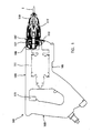
- the body 103 includes a motor housing 105 and a clutch housing 107.
- the motor housing 103 houses a driving motor 111.
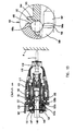
- the clutch housing 107 houses a clutch mechanism 131 that transmits the rotating output of the motor 111 to the spindle 117 or stops the transmission of the rotating output.
- the direction of rotation of the driving motor 111 can be selected between normal and reverse directions by operating a rotation selection switch (rotation selecting member) which is not shown.
- the auxiliary clutch teeth 137a are located forward of the driving-side clutch teeth 133a in the direction of normal rotation when the driving-side clutch member 133 is caused to rotate by the torque of the driving motor 111 in the normal direction.
- the driven-side clutch teeth 135a of the spindle-side clutch member 135 engage with the auxiliary clutch teeth 137a before the driving-side clutch teeth 133a.
- the mating surfaces of the clutch teeth 133a and the auxiliary clutch teeth 137a with the driven-side clutch teeth 135a are shaped such that they engage in surface contact.
- the lead grooves 153 are formed in the driving-side clutch member 133 at equal intervals (of 120°) with respect to each other in the circumferential direction and have a predetermined length in the circumferential direction.
- the lead grooves 153 are open on the rear side of the driving-side clutch member 133.
- the inside of a groove bottom 153a of each of the lead grooves 153 is continuous with the above-mentioned circular recess 133b. Therefore, parts of the steel balls 151 in the lead grooves 153 face the rear surface of the clutch cam 137 and engage with concave cam faces 155 that are formed in the clutch cam 137 at intervals of 120° with respect to each other in the circumferential direction.
- a stepped portion 166 is radially formed in a portion of the outer peripheral surface of the support shaft 143 which is inserted into the cylindrical portion 163 of the spindle 117.
- the stepped portion 166 has an inclined surface 166a that is inclined or tapered forward (rightward as viewed in the drawings).
- the support shaft 143 has a small-diameter portion 167 and a large-diameter portion 168, and the stepped portion 166 contiguously connect the small-diameter portion 167 and the large-diameter portion 168 by means of the inclined surface 166a.
- the projection 171d of the driving-side end surface cam portion 171 and the projection 173d of the driven-side end surface cam portion 173 are rectangular as shown in the drawings. Therefore, as shown in FIG. 15, the projections 171d, 173d slide on the inclined surfaces 171a, 173a in line contact via corners 171e, 173e. Thus, the projections 171d, 173d can slide smoothly with low friction. Further, the projections 171d, 173d make surface contact with the flat engagement position holding surfaces 171c, 173c. Therefore, the engagement between the auxiliary clutch teeth 137a and the driven-side clutch teeth 135a can be maintained even if, for example, the driving-side clutch member 133 and the clutch cam 137 slightly move in the circumferential direction with respect to each other.
- FIGS. 3 to 6 show the operation of the clutch mechanism 131 during the tightening operation step by step.
- FIGS. 7 to 10 show the operation of components of the clutch mechanism 131 during the tightening operation in the order corresponding to that of FIGS. 3 to 6.
- FIGS. 11 to 13 show the operation of the engagement speedup mechanism 161 of the clutch mechanism 131 step by step.
- the steel balls 162 of the engagement speedup mechanism 161 contact the small-diameter portion 167 of the support shaft 143 and protrude deepest into the inside of the cylindrical portion 163 of the spindle 117 (see FIG. 11). Further, the auxiliary clutch teeth 137a are located forward of the driving-side clutch teeth 133a in the rotational direction by the angle ⁇ . Each of the steel balls 151 is located in the deepest part of the groove bottom 153a of the associated lead groove 153 of the driving-side clutch member 133 (see FIG. 7).
- each of the steel balls 151 fitted in the lead grooves 153 of the driving-side clutch member 133 is pushed by the associated cam face 155 of the clutch cam 137 and moved along the inclined surface of the groove bottom 153a toward a shallower part of the groove bottom 153a (upward as viewed in FIG. 9) within the associated lead groove 153 (see FIGS. 9(A) and 9(C)).
- part of the steel ball 151 protrudes from the rear surface 133c of the driving-side clutch member 133 toward the thrust bearing 147.
- the clutch cam 137 which has engaged with the driven-side clutch teeth 135a of the spindle-side dutch member 135 receives a rotating torque from the spindle-side clutch member 135 and moves in a direction that delays (retracts) with respect to the rotation in the normal direction while compressing the compression coil spring 149. Therefore, the impact of engagement between the auxiliary clutch teeth 137a and the driven-side clutch teeth 135a can also be alleviated. Further, the driving-side clutch teeth 133a and the auxiliary clutch teeth 137a engage with the driven-side clutch teeth 135a in surface contact.
- the mating surfaces of the clutch teeth 133a, 135a, 137a are flat and extend in directions crossing the circumferential direction. Therefore, the load per unit contact area on the mating surfaces can be reduced, and friction can be reduced.
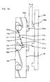
- the engagement position changing mechanism 181 includes a disc-like washer 183 and a plate-like engagement position selection lever 185. As shown in FIGS. 17 to 20, the washer 183 and the engagement position selection lever 185 are disposed between the fan housing 106 and the thrust bearing 147.
- the fan housing 106 is disposed between the motor housing 105 and the clutch housing 107.
- the washer 183 serves also as one roller bearing which is a component of the thrust bearing 147.
- two projections 183b extend from the outer peripheral surface of the washer 183 and slidably engage in associated guide grooves 106a of the fan housing 106.
- the washer 183 can move in the axial direction of the support shaft 143 via the projections 183b.
- FIGS. 23 and 24 are sectional views taken along line B-B in FIG. 17, and in the circles above the sectional views are shown the engaged or disengaged state of the end surface teeth 183a, 185a.
- the operation of selecting the direction of rotation of the motor 111 is interlocked with the operation of selecting the mode of operation of the driver bit 119.
- the ease of operation can be improved and the operational misidentification can be avoided.
- the electric screwdriver 101 for tightening the screw S has been described as a representative example of the "tightening tool" according to the present invention.
- the present invention is not limited to the screwdriver 101, but may be applied to any tightening tool in which the torque of the driving motor 111 is transmitted to the tool bit via the clutch mechanism.
- the driving-side clutch member 133 is disposed on the outer side and the clutch cam 137 is disposed on the inner side, they may be disposed vice versa.
- the engagement speedup mechanism 161 has been described as being disposed between the spindle 117 and the spindle-side clutch member 135. However, it may be constructed without the engagement speedup mechanism 161. In this case, the spindle 117 and the spindle-side clutch member 135 may be formed into one piece.
- the engagement position selection lever 185 may be manually operated at a position outside of the rotating radius of the end surface teeth 183a, 185a such that the lever 185 functions as a cantilever.
- the engagement position selection lever 185 may extend to cross the longitudinal axis of the driving-side clutch member 133. Further, the extending direction of the engagement position selection lever 185 may preferably coincides with the longitudinal direction of the body 103 in the cross-section of the body 103 in order to utilize inner space of the body 103. Further, the engagement position selection lever 185 may be operated in the circumferential direction by utilizing a linkage defined by the arm 193b.
Landscapes
- Engineering & Computer Science (AREA)
- Mechanical Engineering (AREA)
- Details Of Spanners, Wrenches, And Screw Drivers And Accessories (AREA)
Applications Claiming Priority (1)
| Application Number | Priority Date | Filing Date | Title |
|---|---|---|---|
| JP2004307465A JP4327061B2 (ja) | 2004-10-21 | 2004-10-21 | 締付け工具 |
Publications (3)
| Publication Number | Publication Date |
|---|---|
| EP1649979A2 true EP1649979A2 (fr) | 2006-04-26 |
| EP1649979A3 EP1649979A3 (fr) | 2008-01-23 |
| EP1649979B1 EP1649979B1 (fr) | 2012-12-12 |
Family
ID=35587044
Family Applications (1)
| Application Number | Title | Priority Date | Filing Date |
|---|---|---|---|
| EP05023028A Expired - Fee Related EP1649979B1 (fr) | 2004-10-21 | 2005-10-21 | Outil de serrage |
Country Status (4)
| Country | Link |
|---|---|
| US (1) | US7669507B2 (fr) |
| EP (1) | EP1649979B1 (fr) |
| JP (1) | JP4327061B2 (fr) |
| CN (1) | CN100372652C (fr) |
Cited By (2)
| Publication number | Priority date | Publication date | Assignee | Title |
|---|---|---|---|---|
| EP2200772A4 (fr) * | 2007-09-06 | 2011-04-27 | Demain Technology Pty Ltd | Ensemble mécanique destiné à une machine-outil |
| CN102343573A (zh) * | 2010-07-22 | 2012-02-08 | 株式会社牧田 | 螺钉拧紧工具 |
Families Citing this family (17)
| Publication number | Priority date | Publication date | Assignee | Title |
|---|---|---|---|---|
| JP5099440B2 (ja) * | 2008-05-27 | 2012-12-19 | 日立工機株式会社 | ねじ締め機 |
| ES2389326T3 (es) * | 2008-05-27 | 2012-10-25 | Hitachi Koki Co., Ltd. | Destornillador |
| US8479964B2 (en) * | 2010-04-05 | 2013-07-09 | Makita Corporation | Dust collecting devices |
| TWI491477B (zh) * | 2012-09-21 | 2015-07-11 | Nitto Kohki Co | Electric screwdriver |
| DE102012221906B4 (de) * | 2012-11-29 | 2021-12-30 | Robert Bosch Gmbh | Handwerkzeugmaschine mit einer Drehmomentkupplung |
| JP6235872B2 (ja) * | 2013-11-07 | 2017-11-22 | 株式会社マキタ | 作業工具 |
| JP6290041B2 (ja) * | 2014-08-27 | 2018-03-07 | 株式会社マキタ | ねじ締め工具 |
| TWI501841B (zh) * | 2014-10-17 | 2015-10-01 | Chung Taan Ind Co Ltd | 接頭 |
| CN105619342B (zh) * | 2014-10-28 | 2018-01-19 | 南京德朔实业有限公司 | 电动工具 |
| DE102015111570A1 (de) * | 2015-07-16 | 2017-01-19 | Jörg Hohmann | Drehschrauber |
| CN105666393B (zh) * | 2015-12-31 | 2018-01-09 | 宁波中旺工具有限公司 | 一种电动螺丝刀 |
| JP6759815B2 (ja) * | 2016-07-29 | 2020-09-23 | 工機ホールディングス株式会社 | 電動工具 |
| JP7231329B2 (ja) * | 2018-02-19 | 2023-03-01 | 株式会社マキタ | ネジ締め工具 |
| US11607780B2 (en) | 2018-02-19 | 2023-03-21 | Makita Corporation | Work tool |
| JP7217077B2 (ja) * | 2019-04-16 | 2023-02-02 | 株式会社マキタ | ネジ締め工具 |
| US12233523B2 (en) | 2020-12-07 | 2025-02-25 | Black & Decker Inc. | Power tool with multiple modes of operation and ergonomic handgrip |
| DE102022213145A1 (de) | 2022-12-06 | 2024-06-06 | Robert Bosch Gesellschaft mit beschränkter Haftung | Schrauber mit Rastkupplung |
Family Cites Families (14)
| Publication number | Priority date | Publication date | Assignee | Title |
|---|---|---|---|---|
| US4573370A (en) * | 1983-07-08 | 1986-03-04 | The Rotor Tool Company | Gear reversing mechanism for power tools |
| JPS61121877A (ja) * | 1984-11-16 | 1986-06-09 | 松下電器産業株式会社 | 電動ドライバ− |
| DE3510605A1 (de) * | 1985-03-23 | 1986-10-02 | C. & E. Fein Gmbh & Co, 7000 Stuttgart | Kupplung fuer kraftgetriebene schraubwerkzeuge |
| DE3831960A1 (de) * | 1988-09-21 | 1990-03-22 | Scintilla Ag | Geraeuscharme schrauberkupplung |
| US5156244A (en) * | 1990-08-31 | 1992-10-20 | The Aro Corporation | Torque sensing automatic shut-off and reset clutch for screwdrivers, nutsetters and the like |
| JPH0825146B2 (ja) * | 1990-09-19 | 1996-03-13 | 株式会社マキタ | 電動スクリュードライバにおけるクラッチ装置 |
| JP3071523B2 (ja) * | 1991-10-08 | 2000-07-31 | 株式会社マキタ | スクリュードライバーにおける回り止め装置 |
| US5372206A (en) * | 1992-10-01 | 1994-12-13 | Makita Corporation | Tightening tool |
| JP3298944B2 (ja) | 1992-10-01 | 2002-07-08 | 株式会社マキタ | サイレントクラッチ付締付工具 |
| US5538089A (en) * | 1995-06-05 | 1996-07-23 | The Black & Decker Corporation | Power tool clutch assembly |
| DE19845024C2 (de) | 1998-09-30 | 2000-08-03 | Fein C & E | Kraftgetriebener Schrauber |
| DE10308272B4 (de) * | 2002-03-05 | 2012-05-24 | Makita Corp. | Schraubendreher |
| JP3996475B2 (ja) * | 2002-09-13 | 2007-10-24 | 株式会社信濃製作所 | エアインパクトレンチ |
| JP4270927B2 (ja) | 2003-04-14 | 2009-06-03 | 株式会社マキタ | 電動スクリュードライバ |
-
2004
- 2004-10-21 JP JP2004307465A patent/JP4327061B2/ja not_active Expired - Fee Related
-
2005
- 2005-07-04 CN CNB2005100820196A patent/CN100372652C/zh not_active Expired - Fee Related
- 2005-10-21 EP EP05023028A patent/EP1649979B1/fr not_active Expired - Fee Related
- 2005-10-21 US US11/254,739 patent/US7669507B2/en not_active Expired - Fee Related
Cited By (3)
| Publication number | Priority date | Publication date | Assignee | Title |
|---|---|---|---|---|
| EP2200772A4 (fr) * | 2007-09-06 | 2011-04-27 | Demain Technology Pty Ltd | Ensemble mécanique destiné à une machine-outil |
| CN102343573A (zh) * | 2010-07-22 | 2012-02-08 | 株式会社牧田 | 螺钉拧紧工具 |
| CN102343573B (zh) * | 2010-07-22 | 2014-05-07 | 株式会社牧田 | 螺钉拧紧工具 |
Also Published As
| Publication number | Publication date |
|---|---|
| EP1649979B1 (fr) | 2012-12-12 |
| JP2006116657A (ja) | 2006-05-11 |
| EP1649979A3 (fr) | 2008-01-23 |
| US7669507B2 (en) | 2010-03-02 |
| CN100372652C (zh) | 2008-03-05 |
| JP4327061B2 (ja) | 2009-09-09 |
| CN1762665A (zh) | 2006-04-26 |
| US20060086215A1 (en) | 2006-04-27 |
Similar Documents
| Publication | Publication Date | Title |
|---|---|---|
| EP1649979B1 (fr) | Outil de serrage | |
| EP1574294B1 (fr) | Dispositif de commande à percussion | |
| US7131503B2 (en) | Impact driver having a percussion application mechanism which operation mode can be selectively switched between percussion and non-percussion modes | |
| US8944179B2 (en) | Power tool | |
| EP1714745A2 (fr) | Mécanisme de sélecteur de mode pour un outil à percussion | |
| US20040211576A1 (en) | Multispeed power tool transmission | |
| US6176162B1 (en) | Power-driven screwdriver with removable depth stop | |
| EP2103390A2 (fr) | Outil électrique comportant des moyens pour sélectionner un mode de fonctionnement parmi plusieurs modes de fonctionnement | |
| US7712546B2 (en) | Power tool having torque limiter | |
| EP1759792B1 (fr) | Outil motorisé avec système de mandrin avec verrouillage de la broche et manchon coulissant | |
| US6105450A (en) | Speed change device for power tool | |
| EP0666145A1 (fr) | Méchanisme d'embrayage pour tournevis motorisé | |
| US20030233917A1 (en) | Screwdriver | |
| EP1649978A2 (fr) | Outil de serrage | |
| EP2409814B1 (fr) | Mécanismes d'embrayage pour tournevis électriques | |
| JPH11123671A (ja) | 電動工具の変速装置 | |
| JP4557673B2 (ja) | 締付け工具 |
Legal Events
| Date | Code | Title | Description |
|---|---|---|---|
| PUAI | Public reference made under article 153(3) epc to a published international application that has entered the european phase |
Free format text: ORIGINAL CODE: 0009012 |
|
| AK | Designated contracting states |
Kind code of ref document: A2 Designated state(s): AT BE BG CH CY CZ DE DK EE ES FI FR GB GR HU IE IS IT LI LT LU LV MC NL PL PT RO SE SI SK TR |
|
| AX | Request for extension of the european patent |
Extension state: AL BA HR MK YU |
|
| PUAL | Search report despatched |
Free format text: ORIGINAL CODE: 0009013 |
|
| AK | Designated contracting states |
Kind code of ref document: A3 Designated state(s): AT BE BG CH CY CZ DE DK EE ES FI FR GB GR HU IE IS IT LI LT LU LV MC NL PL PT RO SE SI SK TR |
|
| AX | Request for extension of the european patent |
Extension state: AL BA HR MK YU |
|
| 17P | Request for examination filed |
Effective date: 20080716 |
|
| AKX | Designation fees paid |
Designated state(s): DE FR GB |
|
| 17Q | First examination report despatched |
Effective date: 20090326 |
|
| GRAP | Despatch of communication of intention to grant a patent |
Free format text: ORIGINAL CODE: EPIDOSNIGR1 |
|
| GRAS | Grant fee paid |
Free format text: ORIGINAL CODE: EPIDOSNIGR3 |
|
| GRAA | (expected) grant |
Free format text: ORIGINAL CODE: 0009210 |
|
| AK | Designated contracting states |
Kind code of ref document: B1 Designated state(s): DE FR GB |
|
| REG | Reference to a national code |
Ref country code: GB Ref legal event code: FG4D |
|
| REG | Reference to a national code |
Ref country code: DE Ref legal event code: R096 Ref document number: 602005037372 Country of ref document: DE Effective date: 20130207 |
|
| PLBE | No opposition filed within time limit |
Free format text: ORIGINAL CODE: 0009261 |
|
| STAA | Information on the status of an ep patent application or granted ep patent |
Free format text: STATUS: NO OPPOSITION FILED WITHIN TIME LIMIT |
|
| 26N | No opposition filed |
Effective date: 20130913 |
|
| REG | Reference to a national code |
Ref country code: DE Ref legal event code: R097 Ref document number: 602005037372 Country of ref document: DE Effective date: 20130913 |
|
| PGFP | Annual fee paid to national office [announced via postgrant information from national office to epo] |
Ref country code: DE Payment date: 20131016 Year of fee payment: 9 Ref country code: FR Payment date: 20131009 Year of fee payment: 9 Ref country code: GB Payment date: 20131016 Year of fee payment: 9 |
|
| REG | Reference to a national code |
Ref country code: DE Ref legal event code: R119 Ref document number: 602005037372 Country of ref document: DE |
|
| GBPC | Gb: european patent ceased through non-payment of renewal fee |
Effective date: 20141021 |
|
| PG25 | Lapsed in a contracting state [announced via postgrant information from national office to epo] |
Ref country code: GB Free format text: LAPSE BECAUSE OF NON-PAYMENT OF DUE FEES Effective date: 20141021 Ref country code: DE Free format text: LAPSE BECAUSE OF NON-PAYMENT OF DUE FEES Effective date: 20150501 |
|
| REG | Reference to a national code |
Ref country code: FR Ref legal event code: ST Effective date: 20150630 |
|
| PG25 | Lapsed in a contracting state [announced via postgrant information from national office to epo] |
Ref country code: FR Free format text: LAPSE BECAUSE OF NON-PAYMENT OF DUE FEES Effective date: 20141031 |