EP1649979B1 - Spannwerkzeug - Google Patents
Spannwerkzeug Download PDFInfo
- Publication number
- EP1649979B1 EP1649979B1 EP05023028A EP05023028A EP1649979B1 EP 1649979 B1 EP1649979 B1 EP 1649979B1 EP 05023028 A EP05023028 A EP 05023028A EP 05023028 A EP05023028 A EP 05023028A EP 1649979 B1 EP1649979 B1 EP 1649979B1
- Authority
- EP
- European Patent Office
- Prior art keywords
- side clutch
- driving
- clutch element
- clutch
- driven
- Prior art date
- Legal status (The legal status is an assumption and is not a legal conclusion. Google has not performed a legal analysis and makes no representation as to the accuracy of the status listed.)
- Expired - Fee Related
Links
- 238000003825 pressing Methods 0.000 claims description 13
- 230000007246 mechanism Effects 0.000 description 105
- 229910000831 Steel Inorganic materials 0.000 description 46
- 239000010959 steel Substances 0.000 description 46
- 230000006835 compression Effects 0.000 description 23
- 238000007906 compression Methods 0.000 description 23
- 238000010276 construction Methods 0.000 description 11
- 230000004048 modification Effects 0.000 description 8
- 238000012986 modification Methods 0.000 description 8
- 230000001934 delay Effects 0.000 description 6
- 238000000034 method Methods 0.000 description 6
- 230000002093 peripheral effect Effects 0.000 description 6
- 230000005540 biological transmission Effects 0.000 description 5
- 230000013011 mating Effects 0.000 description 5
- 230000008859 change Effects 0.000 description 4
- 230000008878 coupling Effects 0.000 description 3
- 238000010168 coupling process Methods 0.000 description 3
- 238000005859 coupling reaction Methods 0.000 description 3
- 230000000994 depressogenic effect Effects 0.000 description 3
- 238000006073 displacement reaction Methods 0.000 description 3
- 230000002035 prolonged effect Effects 0.000 description 2
- 240000006829 Ficus sundaica Species 0.000 description 1
- 230000002411 adverse Effects 0.000 description 1
- 230000004323 axial length Effects 0.000 description 1
- 230000007423 decrease Effects 0.000 description 1
- 230000001419 dependent effect Effects 0.000 description 1
- 230000000881 depressing effect Effects 0.000 description 1
- 230000000694 effects Effects 0.000 description 1
- 230000006872 improvement Effects 0.000 description 1
- 238000004519 manufacturing process Methods 0.000 description 1
- 238000011017 operating method Methods 0.000 description 1
- 238000005096 rolling process Methods 0.000 description 1
Images


Classifications
-
- B—PERFORMING OPERATIONS; TRANSPORTING
- B25—HAND TOOLS; PORTABLE POWER-DRIVEN TOOLS; MANIPULATORS
- B25F—COMBINATION OR MULTI-PURPOSE TOOLS NOT OTHERWISE PROVIDED FOR; DETAILS OR COMPONENTS OF PORTABLE POWER-DRIVEN TOOLS NOT PARTICULARLY RELATED TO THE OPERATIONS PERFORMED AND NOT OTHERWISE PROVIDED FOR
- B25F5/00—Details or components of portable power-driven tools not particularly related to the operations performed and not otherwise provided for
- B25F5/001—Gearings, speed selectors, clutches or the like specially adapted for rotary tools
-
- B—PERFORMING OPERATIONS; TRANSPORTING
- B25—HAND TOOLS; PORTABLE POWER-DRIVEN TOOLS; MANIPULATORS
- B25B—TOOLS OR BENCH DEVICES NOT OTHERWISE PROVIDED FOR, FOR FASTENING, CONNECTING, DISENGAGING OR HOLDING
- B25B21/00—Portable power-driven screw or nut setting or loosening tools; Attachments for drilling apparatus serving the same purpose
-
- B—PERFORMING OPERATIONS; TRANSPORTING
- B25—HAND TOOLS; PORTABLE POWER-DRIVEN TOOLS; MANIPULATORS
- B25B—TOOLS OR BENCH DEVICES NOT OTHERWISE PROVIDED FOR, FOR FASTENING, CONNECTING, DISENGAGING OR HOLDING
- B25B23/00—Details of, or accessories for, spanners, wrenches, screwdrivers
- B25B23/14—Arrangement of torque limiters or torque indicators in wrenches or screwdrivers
- B25B23/141—Mechanical overload release couplings
Definitions
- the present invention relates to a tightening tool such as an electric screwdriver used for screw-tightening operation and more patticuiarty, to a tightening tool having a clutch which appropriately provides not only for normal rotation but for reverse rotation.
- the clutch is engaged when the user applies a pressing force on the body of the screwdriver, so that the torque of the driving motor is transmitted to the tool bit. Further, the clutch is disengaged in relation to the tightening depth of the screw. Therefore, when a pressing force of the user is not applied on the body, it may be difficult to keep the clutch in the engaged state in the screwdriver. As a result, screw-loosing operation by rotating the driving motor in a reverse direction may be basically impossible. In this respect, further improvement is required.
- the tightening tool comprises a body, a driving motor housed in the body, a driving-side clutch element, an auxiliary clutch element, a driven-side clutch element, a driven shaft and a tool bit.
- the driving-side clutch element receives torque of the driving motor both in normal rotation and in reverse rotation.
- the auxiliary clutch element is rotated by the driving-side clutch element and can move in the axial direction with respect to the driving-side clutch element.
- the driven-side clutch element releasably engages with the auxiliary clutch element or with both the driving-side clutch element and the auxiliary clutch element.
- the driven-side clutch element receives the torque of the driving-side clutch element and rotates.
- the driven shaft is driven by rotation of the driving-side clutch element.
- the tool bit is connected to the driven shaft to perform a tightening operation and a loosening operation via rotating torque of the driven shaft.
- the driven shaft moves in the axial direction with respect to the body together with the driving-side clutch element.
- the driven-side clutch element is caused to move in the axial direction by application of a pressing force of the user to the body to engage with the driving-side clutch element.
- the torque of the driving motor in the normal direction is transmitted to the tool bit to perform a tightening operation.
- the driving-side clutch element and the auxiliary clutch element are caused to move relatively with respect to each other in the axial direction by rotating torque of the driving-side clutch element and the driving-side clutch element or the auxiliary clutch element engages with the driven-side clutch element.
- the torque of the driving motor in the reverse direction is transmitted to the tool bit to perform a loosening operation.
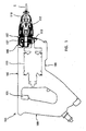
- FIG. 1 shows an entire view of an electric suewdriver 101 as a representative example of the power tool according to the present invention.
- the screwdriver 101 of this embodiment includes a body 103, a driver bit 119 and a handgrip 109.
- the driver bit 119 is detachably coupled to the tip end region of the body 103 via a spindle 117.
- the handgrip 109 is connected to the body 103 on the side opposite to the driver bit 119.
- the spindle 117 is a feature that corresponds to the "driven shaft” according to the present invention.
- the driver bit 119 is a feature that corresponds to the "tool bit” according to the present invention.
- the side of the driver bit 119 is taken as the front side and the side of the handgrip 109 as the rear side.
- the body 103 includes a motor housing 105 and a clutch housing 107.
- the motor housing 103 houses a driving motor 111.
- the clutch housing 107 houses a clutch mechanism 131 that transmits the rotating output of the motor 111 to the spindle 117 or stops the transmission of the rotating output.
- the direction of rotation of the driving motor 111 can be selected between normal and reverse directions by operating a rotation selection switch (rotation selecting member) which is not shown.
- an operation of tightening a screw S on a workpiece W is performed by normal rotation of the motor 111, while an operation of loosening the screw S is performed by reverse rotation of the motor 111.
- rotation of the clutch mechanism 131 as driven by the torque of the motor 111 in the normal direction is referred to as normal rotation or rotation in the normal direction
- rotation of the clutch mechanism 131 as driven by the torque of the motor 111 in the reverse direction is referred to as reverse rotation or rotation in the reverse direction.
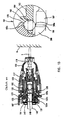
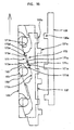
- FIG. 2 shows a detailed construction of the clutch mechanism 131.
- the clutch mechanism 131 includes a driving-side clutch member 133 that is driven by the motor 111, a clutch cam 137 that is disposed on the side of the driving-side clutch member 133 and a spindle-side clutch member 135 that is mounted on the spindle 117, all of which are disposed coaxially.
- the driving-side clutch member 133, the spindle-side clutch member 135 and the clutch cam 137 are features that correspond to the "driving-side clutch element", "driven-side clutch element” and “auxiliary clutch element", respectively, according to the present invention.
- the state in which the driver bit 119 is pressed against the workpiece W via the screw S and a force is acting upon the spindle 117 in the direction that pushes (retracts) the spindle 117 into the body 103 will be referred to as "loaded conditions", while the state in which such force is not acting upon the spindle 117 will be referred to as "unloaded conditions”.
- the clutch teeth 133a of the driving-side clutch member 133, the clutch teeth 135a of the spindle-side clutch member 135 and the clutch teeth 137a of the clutch cam 137 will be referred to as driving-side clutch teeth 133a, driven-side clutch teeth 135a and auxiliary clutch teeth 137a, respectively.
- the spindle 117 is rotatably and axially moveably supported by the clutch housing 107 via a bearing 141.
- the forward movement of the spindle 117 is restricted by contact between a flange 117a of the spindle 117 and an axial end surface of the bearing 141.
- the spindle-side clutch member 135 is fitted on an axially rear end portion of the spindle 117.
- the spindle-side clutch member 135 can rotate together with the spindle 117 and move in the axial direction at higher speed than the spindle 117, via an engagement speedup mechanism 161 which will be described below.
- the driving-side clutch member 133 is press-fitted onto a support shaft 143 and has a driving gear 134 on the outer periphery.
- the driving gear 134 engages with a pinion gear 115 on the output shaft 113 of the motor 111.
- One end of the support shaft 143 is inserted into the bore of a cylindrical portion 163 formed in the rear end portion of the spindle 117 and is supported by the cylindrical portion 163 via a bearing 145 such that the support shaft 143 can move in the axial direction with respect to the spindle 117. Further, the other end of the support shaft 143 is supported by a fan housing 106 via a support ring 186 such that the support shaft 143 can move in the axial direction.
- the fan housing 106 is disposed and joined between the motor housing 105 and the clutch housing 107.
- a thrust bearing 147 is disposed on the rear side (the left side as viewed in FIG. 2 ) of the driving-side clutch member 133.
- the thrust bearing 147 receives a thrust load that is applied to the driving-side clutch member 133 via the compression coil spring 149 during operation of tightening the screw S.
- the axial movement of the thrust bearing 147 is restricted by a steel ball 151 which will be described below.
- a circular recess 133b is centrally formed in the front side of the driving-side clutch member 133 and has a larger diameter than the support shaft 143.
- the ring-shaped clutch cam 137 is fitted in the circular recess 133b.
- the driving-side clutch member 133 and the clutch cam 137 are disposed like coaxially arranged outer and inner rings.
- the rear surface of the clutch cam 137 contacts the bottom of the circular recess 133b.
- the front surface of the clutch cam 137 is flush with or protrudes forward from the front surface of the driving-side clutch member 133.
- the driving-side clutch member 133 and the clutch cam 137 are opposed to the spindle-side clutch member 135.
- the compression coil spring 149 is disposed between the opposed surfaces or between the front-side inner peripheral region of the clutch cam 137 and the rear-side inner peripheral region of the spindle-side clutch member 135.
- the compression coil spring 149 urges the driving-side clutch member 133 and clutch cam 137 and the spindle-side clutch member 135 away from each other.
- a rear surface 133c of the driving-side clutch member 133 is pushed against the thrust bearing 147 by the compression coil spring 149.
- a plurality of (three in this embodiment) driving-side clutch teeth 133a are formed on the front surface of the driving-side clutch member 133 at equal intervals (of 120°) with respect to each other in the circumferential direction.
- three auxiliary clutch teeth 137a are formed on the front surface of the clutch cam 137 at equal intervals of 120° with respect to each other in the circumferential direction.
- three driven-side clutch teeth 135a are formed on the rear surface of the spindle-side clutch member 135 at equal intervals (of 120°) with respect to each other in the circumferential direction.
- the driven-side clutch teeth 135a has a radial length long enough to engage with the driving-side clutch teeth 133a and the auxiliary clutch teeth 137a.
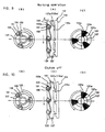
- the dutch teeth 133a, 135a and 137a are shown in FIGS. 7(A), 8(A) , 9(A) and 10(A) in developed view and in FIGS. 7(C). 8(C) , 9(C) and 10(C) in plan view.
- the driving-side clutch member 133 and clutch cam 137 and the spindle-side clutch member 135 are held in the disengaged position (as shown in FIG.
- the driving-side clutch teeth 133a, the driven-side clutch teeth 135a and the auxiliary clutch teeth 137a form the "driving-side clutch part", "driven-side clutch part” and "auxiliary clutch part”, respectively.
- the spindle 117 retracts together with the driver bit 119 with respect to the body 103 of the screwdriver 101.
- the spindle-side clutch member 135 is then caused to move toward the driving-side clutch member 133.
- the driven-side clutch teeth 135a engage with the driving-side clutch teeth 133a and the auxiliary clutch teeth 137a.
- a phase difference of an angle ⁇ is provided in the rotational direction between the driving-side clutch teeth 133a and the auxiliary clutch teeth 137a.
- the auxiliary clutch teeth 137a are located forward of the driving-side clutch teeth 133a in the direction of normal rotation when the driving-side clutch member 133 is caused to rotate by the torque of the driving motor 111 in the normal direction.
- the driven-side clutch teeth 135a of the spindle-side clutch member 135 engage with the auxiliary clutch teeth 137a before the driving-side clutch teeth 133a.
- the mating surfaces of the clutch teeth 133a and the auxiliary clutch teeth 137a with the driven-side clutch teeth 135a are shaped such that they engage in surface contact.
- the driving-side clutch teeth 133a, the driven-side clutch teeth 135a and the auxiliary clutch teeth 137a have flat end surfaces in the circumferential direction which are parallel to each other in the axial direction.
- each of the clutch teeth has flat mating surfaces that extend in directions crossing the circumferential direction.
- the auxiliary clutch teeth 137a are flush with or protrude forward from the front surface of the driving-side clutch teeth 133a.
- the driving-side clutch member 133 and the clutch cam 137 are connected to each other such that they are allowed to move with respect to each other within a predetermined range in the circumferential direction via a plurality of (three in this embodiment) steel balls 151.
- the connection by the steel balls 151 is shown in FIGS. 7(A), 8(A) , 9(A) and 10(A) in developed view and in FIGS. 7(B), 8(B) , 9(B) and 10(B) in plan view.
- the steel balls 151 are fitted in lead grooves 153.
- the lead grooves 153 are formed in the driving-side clutch member 133 at equal intervals (of 120°) with respect to each other in the circumferential direction and have a predetermined length in the circumferential direction.
- the lead grooves 153 are open on the rear side of the driving-side clutch member 133.
- the inside of a groove bottom 153a of each of the lead grooves 153 is continuous with the above-mentioned circular recess 133b. Therefore, parts of the steel balls 151 in the lead grooves 153 face the rear surface of the clutch cam 137 and engage with concave cam faces 155 that are formed in the clutch cam 137 at intervals of 120° with respect to each other in the circumferential direction.
- the driving-side clutch member 133 when the driving-side clutch member 133 is caused to rotate in the normal direction by the driving motor 111, the driving-side clutch member 133 and the clutch cam 137 are allowed to move with respect to each other in the circumferential direction via the steel balls 151 within a predetermined range that is defined by the circumferential length of the lead grooves 153.
- each of the steel balls 151 is located in the deepest region of the groove bottom 153a of the associated lead groove 153 and is flush with the rear surface (the contact surface with the thrust bearing 147) of the driving-side clutch member 133.
- the phase difference of the angle ⁇ is provided in the direction of normal rotation between the driving-side clutch teeth 133a of the driving-side clutch member 133 and the auxiliary clutch teeth 137a of the clutch cam 137. This state is maintained under unloaded conditions in which the driver bit 119 is not pressed against the workpiece W.
- each of the cam faces 155 of the clutch cam 137 pushes the associated steel ball 151 toward a shallower part of the groove bottom 153a of the associated lead groove 153.
- parts of the steel balls 151 protrude from the rear surface 133c of the driving-side clutch member 133 toward the thrust bearing 147.
- the driving-side clutch member 133 moves forward (toward the spindle-side clutch member 135) against the biasing force of tha compression coil spring 149.
- the clutch cam 137 receives a load in the circumferential direction from the spindle-side clutch member 135, which causes the clutch cam 137 to move in a direction that delays its rotation with respect to the driving-side clutch member 133.
- the steel balls 151 form axial displacement means for displacing the driving-side clutch member 133 in the axial direction in cooperation with the compression coil spring 149.
- each of the steel balls 151 is caused to move toward a shallower part of the groove bottom 153a within the associated lead groove 153.
- the phase difference of an angle ⁇ between the driving-side clutch teeth 133a and the auxiliary clutch teeth 137a becomes zero, and the driving-side clutch teeth 133a engage with the driven-side clutch teeth 135a.
- it may be constructed such that both the driving-side clutch teeth 133a and the auxiliary clutch teeth 137a engage with the driven-side clutch teeth 135a and transmit the power.
- connection between the driving-side clutch member 133 and the clutch cam 137 in the circumferential direction by using the steel balls 151 is made with respect to the direction of normal rotation when the motor 111 is driven in the normal direction.
- Connection between the driving-side clutch member 133 and the clutch cam 137 with respect to the direction of reverse rotation when the motor 111 is driven in the reverse direction will be described below.
- the driver bit 119 is detachably coupled to the tip end portion (front end portion) of the spindle 117. Further, an adjuster sleeve 123 is fitted on the front end portion of the clutch housing 107 and can adjust its axial position. A stopper sleeve 125 is detachably mounted on the front end of the adjuster sleeve 123. The amount of protrusion of the driver bit 119 from the tip end of the stopper sleeve 125 is adjusted by adjusting the axial position of the adjuster sleeve 123. In this manner, the tightening depth of the screw S can be adjusted.
- the engagement speedup mechanism 161 of the clutch mechanism 131 will now be explained.
- the driver bit 119 is pressed against the workpiece W via the screw S in order to tighten the screw S, the spindle 117 retracts with respect to the body 103.
- the engagement speedup mechanism 161 serves to engage the driven-side clutch teeth 135a of the spindle-side clutch member 135 with the driving-side clutch teeth 133a and the auxiliary clutch teeth 137a at higher speed than the moving speed of the spindle 117.
- the engagement speedup mechanism 161 includes a plurality of (three in this embodiment) steel balls 162.
- the steel balls 162 are disposed between the spindle 117 and the spindle-side clutch member 135 and serves to connect the spindle 117 and the spindle-side clutch member 135.
- FIGS. 11 to 13 show the operation of the engagement speedup mechanism 161 and only the engagement speedup mechanism 161 is shown in enlarged view in a circle on the right side of each of the drawings.
- the cylindrical portion 163 is formed in the rear end portion of the spindle 117.
- the spindle-side clutch member 135 is fitted on the rear end of the cylindrical portion 163 such that it can move in the axial direction with respect to the spindle 117. Forward movement of the spindle-side clutch member 135 is prevented by contact of the inclined front surface of the spindle-side clutch member 135 with the inclined surface of a stopper ring 127 that is mounted to the clutch housing 107.
- Three through holes 164 are formed in a portion of the cylindrical portion 163 of the spindle 117 which engages with the spindle-side clutch member 135 and extend radially through the cylindrical portion 163.
- the through holes 164 are arranged at equal intervals (of 120°) with respect to each other in the circumferential direction. Further, engagement recesses 165 are formed in the inner peripheral surface of the spindle-side clutch member 135 in positions which correspond to the positions of the through holes 164.
- the steel balls 162 engage with the engagement recesses 165.
- Each of the engagement recesses 165 has a generally quarter-spherical, inclined surface 165a that is inclined in such a manner as to widen forward (rightward as viewed in the drawings).
- Each of the steel balls 162 has such a large diameter that the steel ball 162 fitted in the associated through hole 164 protrudes to the outside and inside of the cylindrical portion 163.
- the portion of the steel ball 162 which protrudes to the outside engages with the associated engagement recess 165 of the spindle-side clutch member 135.
- the portion of the steel ball 162 which protrudes to the inside engages with the outer peripheral surface of the above-mentioned support shaft 143 within the cylindrical portion 163.
- the spindle-side clutch member 135 and the spindle 117 are integrated in the circumferential direction via the steel balls 162, but can move in the axial direction with respect to each other.
- a stepped portion 166 is radially formed in a portion of the outer peripheral surface of the support shaft 143 which is inserted into the cylindrical portion 163 of the spindle 117.
- the stepped portion 166 has an inclined surface 166a that is inclined or tapered forward (rightward as viewed in the drawings).
- the support shaft 143 has a small-diameter portion 167 and a large-diameter portion 168, and the stepped portion 166 contiguously connect the small-diameter portion 167 and the large-diameter portion 168 by means of the inclined surface 166a.
- the steel balls 162 contact the small-diameter portion 167 of the support shaft 143.
- the steel balls 162 slide over the stepped portion 166.
- each of the steel balls 162 further protrudes to the outside of the cylindrical portion 163 and pushes the inclined surface 165a of the associated engagement recess 165 of the spindle-side clutch member 135.
- the spindle-side clutch member 135 is pushed rearward by axial component force acting upon the inclined surface 165a of the engagement recess 165.
- the spindle-side clutch member 135 retracts at higher speed than the retracting speed of the spindle 117.
- the driving-side clutch member 133 and the dutch cam 137 can move in the circumferential and axial directions with respect to each other via a driving-side end surface cam portion 171 of the driving-side clutch member 133 and a driven-side end surface cam portion 173 of the clutch cam 137.
- the driving-side and driven-side end surface cam portions 171 and 173 are features that correspond to the "inclined surface portions" in the present invention.
- the driving-side and driven-side end surface cam portions 171 and 173 face with each other in the axial direction and have inclined surfaces 171a and 173a, respectively, that are inclined at the same angle and extend in the circumferential direction.
- the driving-side and driven-side end surface cam portions 171 and 173 have flat surfaces 171b and 173b for holding the disengagement position and flat surfaces 171c and 173c for holding the engagement position, respectively.
- the flat surfaces 171b and 173b extend from one longitudinal end of the inclined surfaces 171a and 173a in a direction perpendicular to the axial direction.
- the flat surfaces 171c and 173c extend from the other longitudinal end of the inclined surfaces 171a and 173a in a direction perpendicular to the axial direction.
- projections 171d and 173d are formed on the side of the flat surfaces 171c and 173c for holding the disengagement position and extend from the end surface cam portions 171 and 173 in the axial direction.
- the clutch cam 137 is located apart from the spindle-side clutch member 135, so that the auxiliary clutch teeth 137a are disengaged from the drivcn-side clutch teeth 135a.
- the driving-side clutch member 133 and the clutch cam 137 are prevented from moving in the circumferential direction with respect to each other by contact of a circumferential end surface of the projection 171d of the driving-side end surface cam portion 171 and a circumferential end surface of the projection 173d of the driven-side end surface cam portion 173.
- the projection 171d of the driving-side end surface cam portion 171 contacts the flat engagement position holding surface 173c of the driven-side end surface cam portion 173, while the projection 173d of the driven-side end surface cam portion 173 contacts the flat engagement position holding surface 171c of the driving-side end surface cam portion 171.
- the axial movement of the clutch cam 137 with respect to the driving-side clutch member 133 is limited, so that engagement of the auxiliary clutch teeth 137a and the driven-side clutch teeth 135a is maintained.
- the projection 171d of the driving-side end surface cam portion 171 and the projection 173d of the driven-side end surface cam portion 173 are rectangular as shown in the drawings. Therefore, as shown in FIG. 15 , the projections 171d, 173d slide on the inclined surfaces 171a, 173a in line contact via corners 171e, 173e. Thus, the projections 171d, 173d can slide smoothly with low friction. Further, the projections 171d, 173d make surface contact with the flat engagement position holding surfaces 171c, 173c. Therefore, the engagement between the auxiliary clutch teeth 137a and the driven-side clutch teeth 135a can be maintained even if, for example, the driving-side clutch member 133 and the clutch cam 137 slightly move in the circumferential direction with respect to each other.
- a predetermined clearance C is provided in the circumferential direction between the cam face 155 that is formed in the clutch cam 137 for pressing the steel ball 151 and the projection 171 d of the driving-side end surface cam portion 171.
- the clearance C allows the driving-side clutch member 133 and the clutch cam 137 to move in the circumferential direction with respect to each other when the motor 11 is driven in the normal direction.
- FIGS. 3 to 6 show the operation of the clutch mechanism 131 during the tightening operation step by step.
- FIGS. 7 to 10 show the operation of components of the clutch mechanism 131 during the tightening operation in the order corresponding to that of FIGS. 3 to 6 .
- FIGS. 11 to 13 show the operation of the engagement speedup mechanism 161 of the clutch mechanism 131 step by step.
- FIG. 3 shows the state in which the screw S is set on the driver bit 119 and placed in position on the workpiece W under unloaded conditions in which the screwdriver 101 is not pressed in the screw-tightening direction.
- the spindle-side clutch member 135 is separated from the driving-side clutch member 133 and the clutch cam 137 by the biasing force of the compression coil spring 149.
- the driven-side clutch teeth 135a are not engaged with the driving-side clutch teeth 133a and the auxiliary clutch teeth 137a, so that the clutch mechanism 131 is held disengaged.
- the steel balls 162 of the engagement speedup mechanism 161 contact the small-diameter portion 167 of the support shaft 143 and protrude deepest into the inside of the cylindrical portion 163 of the spindle 117 (see FIG. 11 ). Further, the auxiliary clutch teeth 137a are located forward of the driving-side clutch teeth 133a in the rotational direction by the angle ⁇ . Each of the steel balls 151 is located in the deepest part of the groove bottom 153a of the associated lead groove 153 of the driving-side clutch member 133 (see FIG. 7 ).
- the steel balls 151 do not protrude from the rear surface 133c of the driving-side clutch member 133, and the rear surface 133c of the driving-side clutch member 133 contacts the thrust bearing 147.
- a rotation selecting member of the motor 111 is switched to normal rotation and the trigger 121 is depressed to drive the motor 111, the driving-side clutch member 133 and the clutch cam 137 idle in the direction of normal rotation via the pinion gear 115 and the driving gear 134.
- each of the steel balls 162 is pushed to the outside of the cylindrical portion 163 and pushes the inclined surface 165a of the associated engagement recess 165 of the spindle-side clutch member 135.
- the spindle-side clutch member 135 is pushed rearward by axial component force acting upon the inclined surface 165a of the engagement recess 165.
- the spindle-side clutch member 135 retracts at higher speed than the retracting speed of the spindle 117 (see FIG. 12 ).
- This retracting movement causes the driven-side clutch teeth 135a to move toward the driving-side clutch member 133 and the clutch cam 137.
- the driven-side clutch teeth 135a then engage with the auxiliary clutch teeth 137a before the driving-side clutch teeth 133a because the auxiliary clutch teeth 137a is located forward of the driving-side clutch teeth 133a in the rotational direction by the angle ⁇ .
- the clutch mechanism 131 is engaged and the rotating torque is transmitted to the spindle 117 via the spindle-side clutch member 135 (see FIGS. 4 , 8 and 13 ).
- the spindle 117 and the driver bit 119 rotate in the normal direction and the operation of tightening the screw S is started.
- the clutch cam 137 When the screw-tightening operation is started, the clutch cam 137 receives a load in the circumferential direction via the spindle-side clutch member 135, which causes the clutch cam 137 to move in a direction that delays its rotation with respect to the driving-side clutch member 133. As a result, the phase difference (of an angle ⁇ ) between the driving-side clutch teeth 133a and the auxiliary clutch teeth 137a becomes zero, and the driving-side clutch teeth 133a engage with the driven-side clutch teeth 135a (see FIG. 9(C) ).
- each of the steel balls 151 fitted in the lead grooves 153 of the driving-side clutch member 133 is pushed by the associated cam face 155 of the clutch cam 137 and moved along the inclined surface of the groove bottom 153a toward a shallower part of the groove bottom 153a (upward as viewed in FIG. 9 ) within the associated lead groove 153 (see FIGS. 9(A) and 9(C) ).
- part of the steel ball 151 protrudes from the rear surface 133c of the driving-side clutch member 133 toward the thrust bearing 147.
- the driving-side clutch member 133 and the clutch cam 137 move forward (toward the spindle-side clutch member 135) while compressing the compression coil spring 149.
- the driving-side clutch teeth 133a and the auxiliary clutch teeth 137a engage deeply (completely) with the driven-side clutch teeth 135a.
- a clearance C is created between the rear surface 133c of the driving-side clutch member 133 and the front surface of the thrust bearing 147 (see FIGS. 5 and 9(A) ).
- this clearance C serves to allow the driving-side clutch member 133 and the clutch cam 137 to idle quietly while holding the clutch mechanism 131 in the disengaged state.
- the movement of the driving-side clutch member 133 and the clutch cam 137 toward the spindle-side clutch member 135 to create the clearance C is a silent clutch operation.
- the screw-tightening operation proceeds in the completely engaged state of the clutch mechanism 131 and the tip end of the stopper sleeve 125 contacts the workpiece W.
- the screw S is further tightened by the rotating torque of the spindle 117 and the driver bit 119 because the clutch mechanism 131 is engaged.
- the spindle-side clutch member 135 and the spindle 117 which have been biased forward by the compression coil spring 149 move forward.
- the driven-side clutch teeth 135a gradually move away from the driving-side clutch teeth 133a and the auxiliary clutch teeth 137a into incomplete engagement and finally into complete disengagement. Then, the operation of tightening the screw S is completed.
- each of the steel balls 162 of the engagement speedup mechanism 161 moves from the large-diameter portion 168 of the support shaft 143 to the small-diameter portion 167 via the inclined surface 166a of the stepped portion 166.
- the pressing force of the steel ball 162 is no longer applied on the inclined surface 165a of the associated engagement recess 165, so that the spindle-side clutch member 135 moves forward by the biasing force of the compression coil spring 149.
- the spindle-side clutch member 135 moves forward at higher speed than the spindle 117.
- faster clutch disengagement is achieved. This state is shown in FIGS. 6 and 10 .
- the driving-side clutch member 133 and the clutch cam 137 move into contact with the thrust bearing 147.
- the amount of this travel corresponds to the amount of the clearance C created by the above-mentioned silent clutch operation.
- a proper clearance for avoiding interference is created between the driving-side clutch teeth 133a and auxiliary clutch teeth 137a and the driven-side clutch teeth 135a.
- the driven-side clutch teeth 135a can be held disengaged from the driving-side clutch teeth 133a and auxiliary clutch teeth 137a.
- the clutch mechanism 131 can idle quietly without interference of the driving-side clutch teeth 133a and auxiliary clutch teeth 137a with the driven-side clutch teeth 135a and can suitably perform the function as a silent clutch.
- the clutch mechanism 131 As mentioned above, with the clutch mechanism 131 according to this embodiment, during the operation of tightening the screw S by driving the motor 111 in the normal direction, the driving-side clutch teeth 133a of the driving-side clutch member 133 which is rotated in the normal direction by the motor 111 engage with the driven-side clutch teeth 135a of the spindle-side clutch member 135. However, before this engagement between the clutch teeth 133a and 135a, the auxiliary clutch teeth 137a of the clutch cam 137 which rotates together with the driving-side clutch member 133 engage with the driven-side clutch teeth 135a.
- the clutch cam 137 moves in the circumferential direction with respect to the driving-side clutch member 133 and the driving-side clutch teeth 133a engage with the driven-side clutch teeth 135a.
- the auxiliary clutch teeth 137a of the clutch cam 137 receives an impact load of the engagement of the clutch mechanism 131, and thereafter, the driving-side clutch teeth 133a of the driving-side clutch member 133 engage with the driven-side clutch teeth 135a of the spindle-side clutch member 135.
- the clutch cam 137 serves as a cushion for engagement between the driving-side clutch member 133 and the spindle-side clutch member 135.
- the clutch cam 137 which has engaged with the driven-side clutch teeth 135a of the spindle-side dutch member 135 receives a rotating torque from the spindle-side clutch member 135 and moves in a direction that delays (retracts) with respect to the rotation in the normal direction while compressing the compression coil spring 149. Therefore, the impact of engagement between the auxiliary clutch teeth 137a and the driven-side clutch teeth 135a can also be alleviated. Further, the driving-side clutch teeth 133a and the auxiliary clutch teeth 137a engage with the driven-side clutch teeth 135a in surface contact.
- the mating surfaces of the clutch teeth 133a, 135a, 137a are flat and extend in directions crossing the circumferential direction. Therefore, the load per unit contact area on the mating surfaces can be reduced, and friction can be reduced.
- the clutch cam 137 moves with respect to the driving-side clutch member 133 within a range defined by the circumferential length of the lead groove 153.
- the clutch cam 137 is allowed to further move in a direction that delays its rotation when the driving-side clutch teeth 133a is in engagement with the driven-side clutch teeth 135a. Therefore, the driving-side clutch member 133 can receive the load of disengagement of the clutch mechanism 131, while the clutch cam 137 can receive the load of engagement.
- the clutch mechanism 131 As mentioned above, with the clutch mechanism 131 according to this embodiment, during the operation of tightening the screw S by driving the motor 111 in the normal directio, the impact of the clutch engagement can be alleviated. As a result, durability of the driving-side clutch member 133, the clutch cam 137 and the spindle-side clutch member 135 can be increased, so that the life can be prolonged.
- the clutch cam 137 is disposed within the circular recess 133b of the driving-side clutch member 133, and the front surface of the clutch cam 137 is flush with the front surface of the driving-side clutch member 133.
- the axial length of the clutch mechanism 131 having the clutch cam 137 between the driving-side clutch member 133 and the spindle-side clutch member 135 can be shortened to the same length as a clutch mechanism without the clutch cam 137.
- the length of the screwdriver 101 can be shortened.
- the steel balls 151 are used for silent clutch operation as axial displacement means for displacing the driving-side clutch member 133 in the axial direction.
- Each of the steel balls 151 rolls along the inclined surface of the groove bottom 153a of the associated lead groove 153 of the driving-side clutch member 133. This rolling movement is utilized to move the driving-side clutch member 133 in the axial direction. Therefore, smooth movement of the driving-side clutch member 133 can be achieved with lower frictional resistance.
- the clutch mechanism 131 has the engagement speedup mechanism 161 between the spindle 117 and the spindle-side clutch member 135, which allows the spindle-side clutch member 135 to move at higher speed than the spindle 117.
- the speed of engagement of the driven-side clutch teeth 135a with the auxiliary clutch teeth 137a increases.
- the number of times that the driven-side clutch teeth 135a and the auxiliary clutch teeth 137a ride past each other the number of times that the axial end surfaces of the clutch teeth 135a, 137a interfere with each other
- the friction between the clutch teeth 135a and 137a is reduced, so that the life of the clutch mechanism 131 can be prolonged.
- the inclined surface 165a of the engagement recess 165 of the spindle-side clutch member 135 engages with the associated steel ball 162. Therefore, the rotating torque of the spindle-side clutch member 135 is transmitted to the spindle 117 via the steel balls 162.
- the steel balls 162 serve not only as an engagement speedup member for moving the spindle-side clutch member 135 at higher speed than the spindle 117, but as a member for transmitting the rotating torque. Therefore, the fit between the spindle-side clutch member 135 and the spindle 117 allows transmission of the rotating torque and can be simplified in structure without need for spline engagement.
- FIG. 14 shows the state in which the motor is stopped.
- the projection 171d of the driving-side end surface cam portion 171 and the projection 173d of the driven-side end surface cam portion 173 contact the associated flat surfaces 173b and 171b for keeping the disengagement position, respectively.
- the rotation selecting member of the motor 111 is changed to the reverse direction and the motor 111 is driven in the reverse direction by depressing the trigger 121
- the driving-side clutch member 133 is caused to rotate in the reverse direction via the pinion gear 115 and the driving gear 134.
- the clutch cam 137 is held stationary and the biasing force of the compression coil spring 149 is acting upon the clutch cam 137 as a force of holding it stationary.
- the driving-side clutch member 133 and the clutch cam 137 move in the circumferential direction with respect to each other.
- the projection 171d of the driving-side end surface cam portion 171 slides on the inclined surface 173a of the driven-side end surface cam portion 173, while the projection 173d of the driven-side end surface cam portion 173 slides on the inclined surface 171a of the driving-side end surface cam portion 171.
- this sliding movement causes the clutch cam 137 to move away from the driving-side clutch member 133 against the biasing force of the compression coil spring 149, or toward the driven-side clutch member 135.
- the auxiliary clutch teeth 137a of the clutch cam 137 engage with the driven-side clutch teeth 135a of the spindle-side clutch member 135.
- the clutch mechanism 131 can be directly engaged and the driver bit 119 is caused to rotate in the reverse direction solely by driving the motor 111 in the reverse direction.
- the tip end of the driver bit 119 is placed on the head of the screw S to be loosened, and then the motor 11 is driven in the reverse direction.
- the torque of the motor 111 in the reverse direction can be transmitted from the driving-side clutch member 133 to the driven-side clutch member 135.
- the driver bit 119 can be rotated in the reverse direction without application of the pressing force of the user to the body 103, or without pressing the tip end of the stopper sleeve 125 against the workpiece W. Therefore, the operation of loosening the screw S can be performed with the stopper sleeve 125 left attached to the body 103. Thus, the workability can be improved.
- the axial end surface of the projection 171d of the driving-side end surface cam portion 171 and the axial end surface of the projection 173d of the driven-side end surface cam portion 173 make surface contact with the flat engagement position holding surfaces 173c, 171c in the position in which the driving-side clutch member 133 and the clutch cam 137 are prevented from moving in the circumferential direction with respect to each other by contact between the projections 171d, 173d. In this manner, engagement between the auxiliary clutch teeth 137a and the driven-side clutch teeth 135a is maintained.
- the engagement between the auxiliary clutch teeth 137a and the driven-side clutch teeth 135a can be reliably maintained even if, for example, the driving-side clutch member 133 and the clutch cam 137 slightly displace in the circumferential direction with respect to each other. Therefore, the operation of loosening the screw S can be performed in a stable state.
- the driving-side end surface cam portion 171 and the driven-side end surface cam portion 173 have the inclined surfaces 171 a and 173a, respectively, either of the inclined surfaces may be omitted.
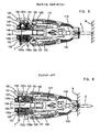
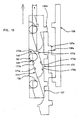
- FIG. 17 shows the entire screwdriver 101 having the clutch mechanism 131 equipped with the engagement position changing mechanism 181.
- FIGS. 18 to 20 show the operation of the clutch mechanism 131.
- FIG. 18 shows the clutch mechanism 131 immediately after operation of tightening the screw S has been completed
- FIG. 19 shows the clutch mechanism 131 at the time of change to the mode of loosening the screw S
- FIG. 20 shows the clutch mechanism 131 during operation of loosening the screw S.
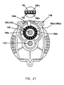
- FIG. 21 is a view taken from the direction shown by arrow "A" in FIG. 19 .
- FIG. 22 shows components of the engagement position changing mechanism 181.
- the engagement position changing mechanism 181 is provided as a means for moving the driving-side clutch teeth 133a and the auxiliary clutch teeth 137a toward and away from the driven-side clutch teeth 135a of the spindle-side clutch member 135 by moving (advancing and retracting) the driving-side clutch member 133 and the clutch cam 137 in the axial direction.
- the position of the mode of loosening the screw S is the forward position to which the driving-side clutch member 133 and the clutch cam 137 are moved toward the spindle-side clutch member 135.
- the position of the mode of tightening the screw S is the rearward position to which the driving-side clutch member 133 and the clutch cam 137 are moved away from the spindle-side clutch member 135.
- the engagement position changing mechanism 181 includes a disc-like washer 183 and a plate-like engagement position selection lever 185. As shown in FIGS. 17 to 20 , the washer 183 and the engagement position selection lever 185 are disposed between the fan housing 106 and the thrust bearing 147.
- the fan housing 106 is disposed between the motor housing 105 and the clutch housing 107.
- the washer 183 serves also as one roller bearing which is a component of the thrust bearing 147.
- two projections 183b extend from the outer peripheral surface of the washer 183 and slidably engage in associated guide grooves 106a of the fan housing 106. The washer 183 can move in the axial direction of the support shaft 143 via the projections 183b.
- the engagement position selection lever 185 is rotatably fitted onto the support ring 186 and can swing on the axis of the support shaft 143.
- the washer 183 and the engagement position selection lever 185 are arranged in a superimposed state on each other and have end surface teeth 183a and 185a, respectively, on the mating faces in the circumferential direction.
- the end surface teeth 183a and 185a can be engaged with each other.
- the end surface teeth 183a of the washer 183 and the end surface teeth 185a of the engagement position selection lever 185 can be switched between the engaged state and the disengaged state by rotation of the washer 183 and the engagement position selection lever 185 with respect to each other.
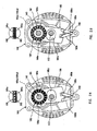
- FIGS. 23 and 24 are sectional views taken along line B-B in FIG. 17 , and in the circles above the sectional views are shown the engaged or disengaged state of the end surface teeth 183a, 185a.
- the engagement position changing mechanism 181 is configured such that the engagement position of the driven-side clutch teeth 135a with the driving-side clutch teeth 133a and the auxiliary clutch teeth 137a can be changed by changing the position of the driving-side clutch member 133 and the clutch cam 137 between the rearward position and the forward position.
- the end surface teeth 183a of the washer 183 and the end surface teeth 185a of the engagement position selection lever 185 have an inclined surface which is inclined at such an angle as to allow smooth disengagement.
- the engagement position selection lever 185 has a clearance hole 185c for avoiding interference with the output shaft 113 of the motor 111.
- a rotation selection switch 187 is mounted on a portion of the motor housing 105 and serves to change the direction of rotation of the motor 111.
- the rotation selection switch 187 has a switch lever 189 which can be operated by rotating between the normal rotation position and the reverse rotation position. The operation force of rotating the switch lever 189 is transmitted to the engagement position selection lever 185 via a coupling mechanism 191.
- the engagement position changing mechanism 181 is configured such that the change of the engagement position between the tightening mode position and the loosening mode position can be interlocked with the rotation selecting operation of the switch lever 189.
- the engagement position selection lever 185 and the switch lever 189 are features that correspond to the "mode selecting member" and the "rotation selecting member", respectively according to the invention.
- the coupling mechanism 191 includes a lever rod 193 which extends parallel to the support shaft 143.
- the lever rod 193 is disposed within the motor housing 105 and the fan housing 106 and can rotate around the axis of the lever rod 193.
- a forked arm 193a is formed on one axial end of the lever rod 193 and engages with an end projection 189a of the switch lever 189 (see FIG. 21 ).
- An arm 193b is formed on the other axial end of the lever rod 193 and engages with a recess 185b formed on the end of the engagement position selection lever 185.
- the engagement position between the clutch teeth 133a, 137a and the driven-side clutch teeth 135a of the spindle-side clutch member 135 is changed to the rearward position.
- engagement of the clutch mechanism 131 is the engagement in the tightening mode. This state is shown in FIG. 17 and corresponds to the unloaded conditions shown in FIG. 3 in the first embodiment.
- the engagement position selection lever 185 is rotated rightward (as viewed in FIG. 24 ) via the lever rod 193. Then, the end surface teeth 185a of the engagement position selection lever 185 disengage from the end surface teeth 183a of the washer 183. As a result, as shown in FIG. 19 , the engagement position selection lever 185 pushes the washer 183 forward, which causes the driving-side clutch member 133 and the clutch cam 137 to move together with the washer 183 toward the spindle-side clutch member 135 against the biasing force of the compression coil spring 149.
- the engagement position of the driven-side clutch teeth 135a with the driving-side clutch teeth 133a and the auxiliary clutch teeth 137a is changed to the forward position. Specifically, the engagement position of the clutch mechanism 131 is changed to the engagement position for the mode of loosening the screw S.
- the trigger 121 is depressed, the motor is driven in the reverse direction, and the tip end of the driver bit 119 which protrudes from the tip end of the stopper sleeve 125 is placed on and pressed against the head of the screw S.
- the spindle-side clutch member 135 is caused to retract together with the driver bit 119 and the spindle 117, and the driven-side clutch teeth 135a engage with the driving-side clutch teeth 133a and the auxiliary clutch teeth 137a.
- the engagement of the driven-side clutch teeth 135a with the driving-side clutch teeth 133a and the auxiliary clutch teeth 137a are deep enough. Therefore, the torque of the motor 11 in the reverse direction is transmitted to the driver bit 119 via the clutch mechanism 131 in the stable state.
- the operation of loosening the screw S can be performed.
- the clutch mechanism 131 engages in the forward position to which the driving-side clutch member 133 and the clutch cam 137 are moved toward the spindle-side clutch member 135.
- the operation of loosening the screw S can be performed with the stopper sleeve 125 left attached to the body 103.
- the workability can be improved.
- the operation of selecting the direction of rotation of the motor 111 is interlocked with the operation of selecting the mode of operation of the driver bit 119.
- the ease of operation can be improved and the operational misidentification can be avoided.
- FIGS. 25 to 27 show a modification of the second embodiment.
- the operating method of the engagement position changing mechanism 181 has been modified from the switch-coupled operation to the manual operation. Specifically, in the modification, the operation of selecting the direction of rotation of the motor 111 and the operation of selecting the clutch engagement position are separately performed.
- This modification has an otherwise identical construction with the second embodiment.
- the engagement position changing mechanism 181 includes the washer 183 and the engagement position selection lever 185 which are arranged in a superimposed state on each other. Part of the engagement position selection lever 185 extends outward through the fan housing 106 that houses the engagement position selection lever 185. A knob 185 is provided on the exposed end of the extended part of the engagement position selection lever 185. Specifically, the engagement position selection lever 185 can be operated from outside the body 103. When the engagement position selection lever 185 is rotated between the tightening operation mode position (see FIG. 26 ) for tightening the screw S and the loosening operation mode position (see FIG.
- the engagement position selection lever 185 is a feature that corresponds to the "mode selecting member" in this invention.
- the engagement of the clutch mechanism 131 is performed in the rearward position when the position selection lever 185 is rotated around the axis of the support shaft 143 to the tightening operation mode position, while the engagement of the clutch mechanism 131 is performed in the forward position when the position selection lever 185 is rotated to the loosening operation mode position. Therefore, according to this modification, the same effect can be obtained as in the second embodiment except for the point that it is not a switch-coupled operation
- the spindle-side clutch member 135 in the loosening operation mode, is retracted together with the driver bit 119 and the spindle 117 after the driving-side clutch teeth 133a and the auxiliary clutch teeth 137a are moved to the forward position, so that the driven-side clutch teeth 135a engage with the driving-side clutch teeth 133a and the auxiliary clutch teeth 137a.
- it may be constructed such that the driven-side clutch teeth 135a engage with the driving-side clutch teeth 133a and the auxiliary clutch teeth 137a via the movement of the driving-side clutch teeth 133a and the auxiliary clutch teeth 137a to the forward position. This construction can be readily realized by further increasing the amount of axial movement of the washer 183 with respect to the engagement position selection lever 185, or by increasing the height of the end surface teeth 183a.
- the electric screwdriver 101 for tightening the screw S has been described as a representative example of the "tightening tool" according to the present invention.
- the present invention is not limited to the screwdriver 101, but may be applied to any tightening tool in which the torque of the driving motor 111 is transmitted to the tool bit via the clutch mechanism.
- the driving-side clutch member 133 is disposed on the outer side and the clutch cam 137 is disposed on the inner side, they may be disposed vice versa.
- the engagement speedup mechanism 161 has been described as being disposed between the spindle 117 and the spindle-side clutch member 135. However, it may be constructed without the engagement speedup mechanism 161. In this case, the spindle 117 and the spindle-side clutch member 135 may be formed into one piece.
- the engagement position selection lever 185 may be manually operated at a position outside of the rotating radius of the end surface teeth 183a, 185a such that the lever 185 functions as a cantilever.
- the engagement position selection lever 185 may extend to cross the longitudinal axis of the driving-side clutch member 133. Further, the extending direction of the engagement position selection lever 185 may preferably coincides with the longitudinal direction of the body 103 in the cross-section of the body 103 in order to utilize inner space of the body 103. Further, the engagement position selection lever 185 may be operated in the circumferential direction by utilizing a linkage defined by the arm 193b.
Landscapes
- Engineering & Computer Science (AREA)
- Mechanical Engineering (AREA)
- Details Of Spanners, Wrenches, And Screw Drivers And Accessories (AREA)
Claims (9)
- Spannwerkzeug (101), enthaltend:einen Körper (103),einen Antriebsmotor (111), der in dem Körper untergebracht ist,ein antriebsseitiges Kupplungselement (133), das das Drehmoment des Antriebsmotors (111) sowohl in einer normalen Richtung als auch in einer Rückwärtsrichtung empfängt,ein Kupplungselement (135) der angetriebenen Seite zum Eingriff mit dem antriebsseitigen Kupplungselement (133), undeine angetriebene Welle (117), die durch die Rotation des antriebsseitigen Kupplungselements (133) angetrieben wird, wobeiein Werkzeugbit (119) mit der angetriebenen Welle (117) zu verbinden ist zum Durchführen eines Spannvorgangs und eines Lockerungsvorgangs über Drehmoment der angetriebenen Welle (117), wobei:die angetriebene Welle (117) sich in der axialen Richtung in Bezug auf den Körper (103) zusammen mit dem antriebsseitigen Kupplungselement (133) bewegt, undwährend einer normalen Rotation des Antriebsmotors (111) das Kupplungselement (135) der angetriebenen Seite dazu gebracht wird, sich in der axialen Richtung zu bewegen durch das Aufbringen einer Druckkraft des Benutzers auf den Körper (103) zum Ineingriffbringen mit dem Kupplungselement (133) der angetriebenen Seite, so dass das Drehmoment des Antriebsmotors (111) in der normalen Richtung an das Werkzeugbit (119) zum Durchführen eines Spannvorgangs übertragen wird,dadurch gekennzeichnet, dassdas Spannwerkzeug (101) weiter ein Hilfskupplungselement (137) enthält, das durch das antriebsseitige Kupplungselement gedreht wird, wobei das Hilfskupplungselement (137) bewegbar in der axialen Richtung in Bezug auf das antriebsseitige Kupplungselement (133) vorgesehen ist, wobei das Kupplungselement der angetriebenen Seite lösbar in Eingriff mit dem Hilfskupplungselement (137) oder mit sowohl dem antriebsseitigen Kupplungselement (133) und dem Hilfskupplungselement (137) gelangt, wenn eine Phasendifferenz eines Winkels a zwischen den antriebsseitigen Kupplungselement (133) und dem Hilfskupplungselement (137) null wird, so dass das Drehmoment des antriebsseitigen Kupplungselements (133) zur Drehung aufgenommen wird,und während der Rückwärtsrotation des Antriebsmotors (111) das antriebsseitige Kupplungselement (133) und das Hilfskupplungselement (137) dazu gebracht werden, sich relativ im Bezug zueinander in der axialen Richtung durch Drehmoment des antriebsseitigen Kupplungselements (133) zu bewegen und das Hilfskupplungselement (137) mit dem Kupplungselement (135) der angetriebenen Seite in Eingriff gelangt, so dass das Drehmoment des Antriebsmotors (111) in der Rückwärtsrichtung an das Werkzeugbit (119) zum Durchführen eines Lockerungsvorgangs übertragen wird.
- Spannwerkzeug (101) nach Anspruch 1, weiter enthaltend eine Stützwelle (143), die durch den Antriebsmotor (111) gedreht wird, wobei das antriebsseitige Kupplungselement (133) und das Hilfskupplungselement (137) koaxial auf der Stützwelle (143) im gleichen Gebiet in der Längsrichtung der Stützwelle (143) angeordnet sind, so dass eines aus dem antriebsseitigen Kupplungselement (133) und dem Hilfskupplungselement (137) einen äußeren Ring bildet und das andere einen inneren Ring bildet.
- Spannwerkzeug (101) nach Anspruch 1 oder 2, weiter enthaltend eine geneigte Oberfläche (165a), die auf zumindest einem aus dem antriebsseitigen Kupplungselement (133) und dem Kupplungselement (135) der angetriebenen Seite angeordnet ist, wobei während der Rückwärtsrotation des Antriebsmotors (111) die Axialrelativbewegung des antriebsseitigen Kupplungselements (133) und des Hilfskupplungselements (137) durch eine Bewegung in Bezug aufeinander über die geneigte Oberfläche (165a) innerhalb eines vorgegebenen Bereichs in der Umfangsrichtung hervorgerufen wird, und wobei die axiale Bewegung bewirkt, dass das antriebsseitige Kupplungselement (133) oder das Hilfskupplungselement (137) mit dem Kupplungselement (135) der angetriebenen Seite in Eingriff gelangen und der Eingriff in einer Position aufrechterhalten wird, in der die Relativbewegung in der Umfangsrichtung verhindert ist.
- Spannwerkzeug (101) nach einem der Ansprüche 1 bis 3, wobei das antriebsseitige Kupplungselement (133) sich in der Axialrichtung in Bezug auf den Körper (103) bewegen kann und die angetriebene Welle (117) sich in der Axialrichtung in Bezug auf den Körper (103) zusammen mit dem antriebsseitigen Kupplungselement (133) bewegen kann,
das Spannwerkzeug weiter ein Moduswahlelement (185) zum Wählen zwischen dem Spannbetriebsmodus und dem Lockerungsbetriebsmodus des Werkzeugbits (119) enthält, wobei:wenn das Moduswahlelement (185) betätigt ist zum Auswählen des Spannmodus, das Kupplungselement (135) der angetriebenen Seite dazu gebracht wird, sich in der Axialrichtung zu bewegen, durch Aufbringen einer Druckkraft des Benutzers auf den Körper (103) zum Ineingriffgelangen mit dem antriebsseitigen Kupplungselement (133), so dass das Drehmoment des Antriebsmotors (111) in der normalen Richtung an das Werkzeugbit (119) zum Durchführen eines Spannvorgangs übertragen wird, undwenn das Moduswahlelement (185) betätigt ist, wird zum Auswählen des Lockerungsmodus, das antriebsseitige Kupplungselement (133) dazu gebracht, sich in Richtung des Kupplungselements (135) der angetriebenen Seite durch die Bedienkraft des Moduswahlelements (185) zum Auswählen des Lockerungsmodus zu bewegen und mit dem Kupplungselement (135) der angetriebenen Seite durch diese Bewegung in Richtung des Kupplungselements (135) der angetriebenen Seite oder durch nachfolgendes Aufbringen einer Druckkraft des Benutzers auf den Körper (103) in Eingriff zu gelangen, so dass das Drehmoment des Antriebsmotors (111) in der Rückwärtsrichtung an das Werkzeugbit (119) zum Durchführen eines Lockerungsvorgangs übertragen wird. - Spannwerkzeug (101) nach Anspruch 4, weiter enthaltend ein Drehwahlelement (189), das die Richtung der Rotation des Antriebsmotors (111) zwischen einer normalen Richtung und einer Rückwärtsrichtung wählt, wobei das Moduswahlelement (185) und das Drehwahlelement (189) miteinander gekoppelt sind, so dass das Moduswahlelement (185) den Spannmodus wählt, wenn das Drehwahlelement (189) die normale Richtung wählt, während das Moduswahlelement (185) den Lockerungsmodus wählt, wenn das Drehwahlelement (189) die Rückwärtsrichtung wählt.
- Spannwerkzeug (101) nach Anspruch 4 oder 5, wobei das Moduswahlelement einen Eingriffspositionswahlhebel (185), eine Nutscheibe (183), die mit dem Eingriffspositionswahlhebel (185) überlappt, und ein Paar von Endoberflächenzähnen (183a) enthält, die jeweils auf der Eingriffsoberfläche des Eingriffspositionswahlhebels (185) und der Nutscheibe (183) vorgesehen sind, wobei der Eingriffspositionswahlhebel (185) und die Nutscheibe (183) in der Lage sind, sich relativ zueinander in einer Umfangsrichtung zu drehen, wobei die Nutscheibe (183) dazu gebracht wird, sich über ein Lösen des Paars der Endoberflächenzähne (183a) des Eingriffspositionswahlhebels (185) und der Nutscheibe (183) zu bewegen, wenn der Eingriffspositionswahlhebel (185) in einer Umfangsrichtung gedreht wird, und das antriebsseitige Kupplungselement (133) dazu gebracht wird, sich in Richtung des Kupplungselements (135) der angetriebenen Seite in Abhängigkeit von der Bewegung der Nutscheibe (183) zu bewegen.
- Spannwerkzeug (101) nach Anspruch 6, wobei der Eingriffspositionswahlhebel (185) einen Hebelbetätigungsbereich zum Drehen des Hebels in einer Umfangsrichtung enthält, wobei der Hebelbetätigungsbereich außerhalb des Drehradius der Endoberflächenzähne (183a) angeordnet ist.
- Spannwerkzeug (101) nach Anspruch 6 oder 7, wobei der Eingriffspositionswahlhebel (185) sich erstreckt, dass er die Längsachse des antriebsseitigen Kupplungselements (133) kreuzt, wobei die Erstreckungsrichtung des Eingriffspositionswahlhebels (185) mit der Längsrichtung des Körpers (103) im Querschnitt des Körpers (103) zusammenfällt.
- Spannwerkzeug (101) nach einem der Ansprüche 6 bis 8, weiter enthaltend ein Gestänge (191), wobei der Eingriffspositionswahlhebel (185) in der Umfangsrichtung mittels des Gestänges (191) betätigt wird.
Applications Claiming Priority (1)
| Application Number | Priority Date | Filing Date | Title |
|---|---|---|---|
| JP2004307465A JP4327061B2 (ja) | 2004-10-21 | 2004-10-21 | 締付け工具 |
Publications (3)
| Publication Number | Publication Date |
|---|---|
| EP1649979A2 EP1649979A2 (de) | 2006-04-26 |
| EP1649979A3 EP1649979A3 (de) | 2008-01-23 |
| EP1649979B1 true EP1649979B1 (de) | 2012-12-12 |
Family
ID=35587044
Family Applications (1)
| Application Number | Title | Priority Date | Filing Date |
|---|---|---|---|
| EP05023028A Expired - Fee Related EP1649979B1 (de) | 2004-10-21 | 2005-10-21 | Spannwerkzeug |
Country Status (4)
| Country | Link |
|---|---|
| US (1) | US7669507B2 (de) |
| EP (1) | EP1649979B1 (de) |
| JP (1) | JP4327061B2 (de) |
| CN (1) | CN100372652C (de) |
Cited By (1)
| Publication number | Priority date | Publication date | Assignee | Title |
|---|---|---|---|---|
| DE102022213145A1 (de) | 2022-12-06 | 2024-06-06 | Robert Bosch Gesellschaft mit beschränkter Haftung | Schrauber mit Rastkupplung |
Families Citing this family (18)
| Publication number | Priority date | Publication date | Assignee | Title |
|---|---|---|---|---|
| CN101918163A (zh) * | 2007-09-06 | 2010-12-15 | 迪美科技控股有限公司 | 电动工具的机械组件 |
| JP5099440B2 (ja) * | 2008-05-27 | 2012-12-19 | 日立工機株式会社 | ねじ締め機 |
| EP2127811B1 (de) * | 2008-05-27 | 2012-08-15 | Hitachi Koki CO., LTD. | Schraubendreher |
| US8479964B2 (en) * | 2010-04-05 | 2013-07-09 | Makita Corporation | Dust collecting devices |
| JP5512441B2 (ja) * | 2010-07-22 | 2014-06-04 | 株式会社マキタ | ねじ締め工具 |
| TWI491477B (zh) * | 2012-09-21 | 2015-07-11 | Nitto Kohki Co | Electric screwdriver |
| DE102012221906B4 (de) * | 2012-11-29 | 2021-12-30 | Robert Bosch Gmbh | Handwerkzeugmaschine mit einer Drehmomentkupplung |
| JP6235872B2 (ja) * | 2013-11-07 | 2017-11-22 | 株式会社マキタ | 作業工具 |
| JP6290041B2 (ja) * | 2014-08-27 | 2018-03-07 | 株式会社マキタ | ねじ締め工具 |
| TWI501841B (zh) * | 2014-10-17 | 2015-10-01 | Chung Taan Ind Co Ltd | 接頭 |
| CN105619342B (zh) * | 2014-10-28 | 2018-01-19 | 南京德朔实业有限公司 | 电动工具 |
| DE102015111570A1 (de) * | 2015-07-16 | 2017-01-19 | Jörg Hohmann | Drehschrauber |
| CN105666393B (zh) * | 2015-12-31 | 2018-01-09 | 宁波中旺工具有限公司 | 一种电动螺丝刀 |
| JP6759815B2 (ja) * | 2016-07-29 | 2020-09-23 | 工機ホールディングス株式会社 | 電動工具 |
| JP7231329B2 (ja) * | 2018-02-19 | 2023-03-01 | 株式会社マキタ | ネジ締め工具 |
| US11607780B2 (en) | 2018-02-19 | 2023-03-21 | Makita Corporation | Work tool |
| JP7217077B2 (ja) * | 2019-04-16 | 2023-02-02 | 株式会社マキタ | ネジ締め工具 |
| US12233523B2 (en) | 2020-12-07 | 2025-02-25 | Black & Decker Inc. | Power tool with multiple modes of operation and ergonomic handgrip |
Family Cites Families (14)
| Publication number | Priority date | Publication date | Assignee | Title |
|---|---|---|---|---|
| US4573370A (en) * | 1983-07-08 | 1986-03-04 | The Rotor Tool Company | Gear reversing mechanism for power tools |
| JPS61121877A (ja) * | 1984-11-16 | 1986-06-09 | 松下電器産業株式会社 | 電動ドライバ− |
| DE3510605A1 (de) | 1985-03-23 | 1986-10-02 | C. & E. Fein Gmbh & Co, 7000 Stuttgart | Kupplung fuer kraftgetriebene schraubwerkzeuge |
| DE3831960A1 (de) * | 1988-09-21 | 1990-03-22 | Scintilla Ag | Geraeuscharme schrauberkupplung |
| US5156244A (en) | 1990-08-31 | 1992-10-20 | The Aro Corporation | Torque sensing automatic shut-off and reset clutch for screwdrivers, nutsetters and the like |
| JPH0825146B2 (ja) * | 1990-09-19 | 1996-03-13 | 株式会社マキタ | 電動スクリュードライバにおけるクラッチ装置 |
| JP3071523B2 (ja) * | 1991-10-08 | 2000-07-31 | 株式会社マキタ | スクリュードライバーにおける回り止め装置 |
| JP3298944B2 (ja) | 1992-10-01 | 2002-07-08 | 株式会社マキタ | サイレントクラッチ付締付工具 |
| US5372206A (en) * | 1992-10-01 | 1994-12-13 | Makita Corporation | Tightening tool |
| US5538089A (en) * | 1995-06-05 | 1996-07-23 | The Black & Decker Corporation | Power tool clutch assembly |
| DE19845024C2 (de) * | 1998-09-30 | 2000-08-03 | Fein C & E | Kraftgetriebener Schrauber |
| DE10308272B4 (de) * | 2002-03-05 | 2012-05-24 | Makita Corp. | Schraubendreher |
| JP3996475B2 (ja) * | 2002-09-13 | 2007-10-24 | 株式会社信濃製作所 | エアインパクトレンチ |
| JP4270927B2 (ja) | 2003-04-14 | 2009-06-03 | 株式会社マキタ | 電動スクリュードライバ |
-
2004
- 2004-10-21 JP JP2004307465A patent/JP4327061B2/ja not_active Expired - Fee Related
-
2005
- 2005-07-04 CN CNB2005100820196A patent/CN100372652C/zh not_active Expired - Fee Related
- 2005-10-21 EP EP05023028A patent/EP1649979B1/de not_active Expired - Fee Related
- 2005-10-21 US US11/254,739 patent/US7669507B2/en not_active Expired - Fee Related
Cited By (1)
| Publication number | Priority date | Publication date | Assignee | Title |
|---|---|---|---|---|
| DE102022213145A1 (de) | 2022-12-06 | 2024-06-06 | Robert Bosch Gesellschaft mit beschränkter Haftung | Schrauber mit Rastkupplung |
Also Published As
| Publication number | Publication date |
|---|---|
| JP4327061B2 (ja) | 2009-09-09 |
| JP2006116657A (ja) | 2006-05-11 |
| EP1649979A3 (de) | 2008-01-23 |
| US20060086215A1 (en) | 2006-04-27 |
| CN100372652C (zh) | 2008-03-05 |
| US7669507B2 (en) | 2010-03-02 |
| CN1762665A (zh) | 2006-04-26 |
| EP1649979A2 (de) | 2006-04-26 |
Similar Documents
| Publication | Publication Date | Title |
|---|---|---|
| EP1649979B1 (de) | Spannwerkzeug | |
| US7131503B2 (en) | Impact driver having a percussion application mechanism which operation mode can be selectively switched between percussion and non-percussion modes | |
| EP1574294B1 (de) | Schlagantrieb | |
| US4809572A (en) | Power driven screwdriver | |
| US8944179B2 (en) | Power tool | |
| EP1714745A2 (de) | Betriebsartenwahlmechanismus für ein Schlagwerkzeug | |
| US5568849A (en) | Clutch mechanism in power driven screwdriver | |
| US6176162B1 (en) | Power-driven screwdriver with removable depth stop | |
| EP1834735B1 (de) | Elektrisch angetriebenes Werkzeug mit Drehmomentbegrenzung | |
| EP1759792B1 (de) | Kraftwerkzeug mit Spannfuttersystem mit Spindelverriegelung und Schiebemuffe | |
| US5947210A (en) | Power screwdriver | |
| US6105450A (en) | Speed change device for power tool | |
| US6851343B2 (en) | Screwdriver | |
| EP1649978A2 (de) | Spannwerkzeug | |
| EP2409814B1 (de) | Kupplungsmechanismen für elektrische Schraubendreher | |
| JP4557673B2 (ja) | 締付け工具 | |
| JP3298944B2 (ja) | サイレントクラッチ付締付工具 | |
| JPH06285769A (ja) | サイレントクラッチ付締付工具 |
Legal Events
| Date | Code | Title | Description |
|---|---|---|---|
| PUAI | Public reference made under article 153(3) epc to a published international application that has entered the european phase |
Free format text: ORIGINAL CODE: 0009012 |
|
| AK | Designated contracting states |
Kind code of ref document: A2 Designated state(s): AT BE BG CH CY CZ DE DK EE ES FI FR GB GR HU IE IS IT LI LT LU LV MC NL PL PT RO SE SI SK TR |
|
| AX | Request for extension of the european patent |
Extension state: AL BA HR MK YU |
|
| PUAL | Search report despatched |
Free format text: ORIGINAL CODE: 0009013 |
|
| AK | Designated contracting states |
Kind code of ref document: A3 Designated state(s): AT BE BG CH CY CZ DE DK EE ES FI FR GB GR HU IE IS IT LI LT LU LV MC NL PL PT RO SE SI SK TR |
|
| AX | Request for extension of the european patent |
Extension state: AL BA HR MK YU |
|
| 17P | Request for examination filed |
Effective date: 20080716 |
|
| AKX | Designation fees paid |
Designated state(s): DE FR GB |
|
| 17Q | First examination report despatched |
Effective date: 20090326 |
|
| GRAP | Despatch of communication of intention to grant a patent |
Free format text: ORIGINAL CODE: EPIDOSNIGR1 |
|
| GRAS | Grant fee paid |
Free format text: ORIGINAL CODE: EPIDOSNIGR3 |
|
| GRAA | (expected) grant |
Free format text: ORIGINAL CODE: 0009210 |
|
| AK | Designated contracting states |
Kind code of ref document: B1 Designated state(s): DE FR GB |
|
| REG | Reference to a national code |
Ref country code: GB Ref legal event code: FG4D |
|
| REG | Reference to a national code |
Ref country code: DE Ref legal event code: R096 Ref document number: 602005037372 Country of ref document: DE Effective date: 20130207 |
|
| PLBE | No opposition filed within time limit |
Free format text: ORIGINAL CODE: 0009261 |
|
| STAA | Information on the status of an ep patent application or granted ep patent |
Free format text: STATUS: NO OPPOSITION FILED WITHIN TIME LIMIT |
|
| 26N | No opposition filed |
Effective date: 20130913 |
|
| REG | Reference to a national code |
Ref country code: DE Ref legal event code: R097 Ref document number: 602005037372 Country of ref document: DE Effective date: 20130913 |
|
| PGFP | Annual fee paid to national office [announced via postgrant information from national office to epo] |
Ref country code: DE Payment date: 20131016 Year of fee payment: 9 Ref country code: FR Payment date: 20131009 Year of fee payment: 9 Ref country code: GB Payment date: 20131016 Year of fee payment: 9 |
|
| REG | Reference to a national code |
Ref country code: DE Ref legal event code: R119 Ref document number: 602005037372 Country of ref document: DE |
|
| GBPC | Gb: european patent ceased through non-payment of renewal fee |
Effective date: 20141021 |
|
| PG25 | Lapsed in a contracting state [announced via postgrant information from national office to epo] |
Ref country code: GB Free format text: LAPSE BECAUSE OF NON-PAYMENT OF DUE FEES Effective date: 20141021 Ref country code: DE Free format text: LAPSE BECAUSE OF NON-PAYMENT OF DUE FEES Effective date: 20150501 |
|
| REG | Reference to a national code |
Ref country code: FR Ref legal event code: ST Effective date: 20150630 |
|
| PG25 | Lapsed in a contracting state [announced via postgrant information from national office to epo] |
Ref country code: FR Free format text: LAPSE BECAUSE OF NON-PAYMENT OF DUE FEES Effective date: 20141031 |