EP1649992A1 - Agrafeuse - Google Patents
Agrafeuse Download PDFInfo
- Publication number
- EP1649992A1 EP1649992A1 EP04748259A EP04748259A EP1649992A1 EP 1649992 A1 EP1649992 A1 EP 1649992A1 EP 04748259 A EP04748259 A EP 04748259A EP 04748259 A EP04748259 A EP 04748259A EP 1649992 A1 EP1649992 A1 EP 1649992A1
- Authority
- EP
- European Patent Office
- Prior art keywords
- staple
- leading
- driver
- pusher
- end staple
- Prior art date
- Legal status (The legal status is an assumption and is not a legal conclusion. Google has not performed a legal analysis and makes no representation as to the accuracy of the status listed.)
- Withdrawn
Links
Images


Classifications
-
- B—PERFORMING OPERATIONS; TRANSPORTING
- B27—WORKING OR PRESERVING WOOD OR SIMILAR MATERIAL; NAILING OR STAPLING MACHINES IN GENERAL
- B27F—DOVETAILED WORK; TENONS; SLOTTING MACHINES FOR WOOD OR SIMILAR MATERIAL; NAILING OR STAPLING MACHINES
- B27F7/00—Nailing or stapling; Nailed or stapled work
- B27F7/17—Stapling machines
- B27F7/38—Staple feeding devices
-
- B—PERFORMING OPERATIONS; TRANSPORTING
- B27—WORKING OR PRESERVING WOOD OR SIMILAR MATERIAL; NAILING OR STAPLING MACHINES IN GENERAL
- B27F—DOVETAILED WORK; TENONS; SLOTTING MACHINES FOR WOOD OR SIMILAR MATERIAL; NAILING OR STAPLING MACHINES
- B27F7/00—Nailing or stapling; Nailed or stapled work
- B27F7/17—Stapling machines
- B27F7/19—Stapling machines with provision for bending the ends of the staples on to the work
-
- B—PERFORMING OPERATIONS; TRANSPORTING
- B27—WORKING OR PRESERVING WOOD OR SIMILAR MATERIAL; NAILING OR STAPLING MACHINES IN GENERAL
- B27F—DOVETAILED WORK; TENONS; SLOTTING MACHINES FOR WOOD OR SIMILAR MATERIAL; NAILING OR STAPLING MACHINES
- B27F7/00—Nailing or stapling; Nailed or stapled work
- B27F7/17—Stapling machines
- B27F7/30—Driving means
- B27F7/36—Driving means operated by electric power
Definitions
- the present invention relates to a stapler which staples sheets of paper to be stapled together at a desired position.
- a copier has been known in which a stack tray provided with a stapler that staples copied sheets of paper at a desired position (for example, JP-B2-2778460).
- the stapler is provided with a driver mounted on an upper frame of a frame divided up and low, and the driver is moved up and down by a link mechanism operationally coupled through a drive part such as an electric power motor and a reduction gear.
- a drive part such as an electric power motor and a reduction gear.
- a leading-edge staple is always set in a proper position, that is, in a proper position under the driver, and that unexpected slippage of the staple when the driver pushes out the leading-edge staple is prevented.
- a pusher for pressing the staple to a guide surface by means of energizing force of a spring is provided in the stapler (refer to, for example, JP-A-2000-343451).
- Figs. 3A, 3B and 3C show one example of an electric stapler provided with the pusher.
- Reference numeral 1 is a staple, and at least the leading-edge staple is formed in substantially C-shape.
- Reference numeral 2 is a driver which separates the staple 1 from the next staple 1 and pushes out the staple 1 so as to insert the both ends of the staple 1 into the sheets of paper to be stapled
- reference numeral 3 is a pusher
- reference numeral 4 is a staple guide.
- the staples 1 are formed in a sheet where many staples in straight wire conditions are connected by an adhesive bond.
- the sheet-shaped staples 1 are accommodated in a magazine (not shown) and stacked in an up-and-down direction.
- the staple 1 located in the uppermost (or lowermost) position the staple 1 located in a leading-end position in a front-and-back directionisformedin thesubstantiallyC-shape, and thereafter the C-shaped staple 1 is driven by the driver 2.
- a forming plate (not shown) that descends in synchronization with the driver 2
- the next staple 1 is formed in the C-shape.
- the driver 2 is provided with a pair of leg portions 2a which come into contact with vicinity of both corners of the staple 1 and push out the staple 1 so that the both ends of the C-shaped staple 1 are not deformed unexpectedly, when the staple 1 is penetrating into the comparatively thick sheets of paper to be stapled, by a load from a side of the sheets of paper to be stapled.
- the pusher 3 supports the leading-end staple 1 and the next staple 1, of the sheet-shaped staples 1 accommodated in the magazine and guided by the staple guide 4, in the forming state in the C-shape, and includes a contact surface 3a for pressing the leading-end staple 1 to the guide surface forward.
- the staple 1 is driven to the sheets of paper to be stapled. Therefore, space is formed near the center in the left and right direction of the staple 1.
- an object of the invention is to provide a stapler which is capable of preventing the occurrence of cutting noise when the leading-end staple is torn off from the next staple in order to drive the leading-end staple in the sheets of paper to be stapled.
- the stapler of the invention includes a driver which is movable up and down in relation to a magazine in which sheet-shaped connected staples are accommodated, and a pusher which pushes the C-shaped leading-end staple of the sheet-shaped connected staples to a guide surface for guiding a movement of the driver so that the leading-end staple is opposed to a leading end of the driver.
- the pusher has a support surface which is positioned near and under a center of the staple, and protrudes so that a part of the support surface faces to an inside of at least the C-shaped leading-end staple.
- a protrusion surface of the support surface opposed to the leading-end staple may tilt in the driving direction of the driver.
- Fig. 1A is a perspective view of a main portion of an electric stapler
- Fig. 1B is a front view of the main portion in an initial state when a leading-end staple is torn off from the next staple
- Fig. 1C is a front view of the main portion in a middle state when the leading-end staple is torn off from the next staple
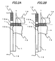
- Fig. 2A is a sectional view of the main portion in the initial state when the leading-end staple is torn off from the next staple
- Fig. 2B is a sectional view of the main portion in the middle state when the leading-end staple is torn off from the next staple.
- reference numeral 1 is a staple. At least a leading-end staple is formed in the C-shape.
- Reference numeral 12 is a driver which separates the staple 1 from the next staple 1 and pushes out the staple 1 so that both ends of the staple 1 penetrate into the sheets of paper to be stapled.
- Reference numeral 13 is a pusher.
- Reference numeral 14 is a staple guide.
- Reference numeral 15 is a guide surface for guiding a slide motion of the driver 12.
- the substantially C-shaped staple has a linear upper portion, and both end portions extending perpendicularly from the left and right ends of the upper portion.
- the driver 15 is provided so that it can move up and down in the up-and-down direction. When the driver 15 is driven downward, it drives the leading-end staple.
- the driver 12 is provided with a pair of leg portions 12a which come into contact with vicinities of both corners of the staple 1 and push out the staple 1 so that the both end of the substantially C-shaped staple 1 is not deformed unexpectedly, when the staple 1 is penetrating into the comparatively thick sheets of paper to be stapled, by a load from the side of the sheets of paper to be stapled.
- the pusher 13 is always urged toward the guide surface 15 side (in the forward direction) by a not-shown spring. Further, the pusher 13 includes a contact surface 13a for pressing the leading-end staple 1 and the next staple 1 of the sheet-shaped staples 1 accommodated in the magazine and guided by the staple guide 14, to the guide surface 15 in a state where their staples 1 are formed in the C-shape; and a support surface 13b which is located near and under the center in the left and right direction of the staple 1 and protrudes so that a part of the support surface faces to at least the leading-end staple 1. Further, it is preferable that the protrusion surface of the support surface 13b to the staple 1 side tilts in the driving direction of the driver 12.
- the leading-end staple 1 intends to separate from the next staple 1.
- the support surface 13b of the pusher 13 is located near the center portion of the leading-end staple 1, and as shown in Fig. 2B, nearly simultaneously with separation start of the leading-end staple 1, the vicinity of the center of the leading-end staple 1 comes into contact with the support surface 13b. Therefore, even if the descending power of the driver 12 is further applied to the staple 1, the leading-end staple 1 is separated from the next staple 1 without the stain, and the occurrence of the cutting noise in tearing-off of the leading-end staple 1 is prevented.
- the both ends of the staple 1 after penetrating the sheets of paper to be stapled are bent on the back surface side of the paper by the known clincher. Hereby, binding of the sheets of paper to be stapled is completed.
- the driver is provided so that it can move up and down in relation to the magazine in which sheet shaped connected staples are accommodated, the vicinity of the center of the C-shaped leading-end staple of the sheet shaped connected staples is pressed to the guide surface by the pusher so as to be opposed to the leading end of the driver, and the pusher includes the support surface which is located near and under the center of the staple and protrudes so that one part faces to the inside of at least the nearly C-shaped leading-end staple. Therefore, it is possible to prevent the cutting noise from being produced when the leading-end staple is torn off from the next staple in order to drive the leading-end staple in the sheets of paper to be stapled.
Landscapes
- Engineering & Computer Science (AREA)
- Mechanical Engineering (AREA)
- Life Sciences & Earth Sciences (AREA)
- Forests & Forestry (AREA)
- Portable Nailing Machines And Staplers (AREA)
- Dovetailed Work, And Nailing Machines And Stapling Machines For Wood (AREA)
Applications Claiming Priority (2)
| Application Number | Priority Date | Filing Date | Title |
|---|---|---|---|
| JP2003285300A JP4228828B2 (ja) | 2003-08-01 | 2003-08-01 | ステープラ |
| PCT/JP2004/011281 WO2005011939A1 (fr) | 2003-08-01 | 2004-07-30 | Agrafeuse |
Publications (2)
| Publication Number | Publication Date |
|---|---|
| EP1649992A1 true EP1649992A1 (fr) | 2006-04-26 |
| EP1649992A4 EP1649992A4 (fr) | 2008-07-02 |
Family
ID=34113875
Family Applications (1)
| Application Number | Title | Priority Date | Filing Date |
|---|---|---|---|
| EP04748259A Withdrawn EP1649992A4 (fr) | 2003-08-01 | 2004-07-30 | Agrafeuse |
Country Status (7)
| Country | Link |
|---|---|
| US (1) | US20060186168A1 (fr) |
| EP (1) | EP1649992A4 (fr) |
| JP (1) | JP4228828B2 (fr) |
| KR (1) | KR20060052944A (fr) |
| CN (1) | CN1829590A (fr) |
| TW (1) | TW200517225A (fr) |
| WO (1) | WO2005011939A1 (fr) |
Families Citing this family (5)
| Publication number | Priority date | Publication date | Assignee | Title |
|---|---|---|---|---|
| JP5262299B2 (ja) * | 2008-05-28 | 2013-08-14 | マックス株式会社 | ホッチキスにおけるクリンチ位置決め機構 |
| CN110193807A (zh) * | 2018-02-24 | 2019-09-03 | 崔成群 | 一种在订书机上的阻止订书钉弯曲的机构 |
| CN109397198A (zh) * | 2018-12-16 | 2019-03-01 | 崔成群 | 一种优化的在订书机上的阻止订书钉弯曲的机构 |
| CN109397199A (zh) * | 2018-12-18 | 2019-03-01 | 崔成群 | 一种简便的在订书机上的阻止订书钉弯曲的机构 |
| CN113561277B (zh) * | 2021-06-07 | 2022-07-08 | 杭州亚太智能装备有限公司 | 一种气动码钉枪 |
Family Cites Families (24)
| Publication number | Priority date | Publication date | Assignee | Title |
|---|---|---|---|---|
| US1554686A (en) * | 1921-03-24 | 1925-09-22 | Hotchkiss Co E H | Staple-driving machine |
| US1654170A (en) * | 1926-02-19 | 1927-12-27 | Neva Clog Products Inc | Stapling machine |
| US1815066A (en) * | 1930-01-28 | 1931-07-21 | Boston Wire Stitcher Co | Stapling machine |
| US1945377A (en) * | 1933-10-25 | 1934-01-30 | Charles B Goodstein | Stapling machine |
| US2086922A (en) * | 1936-02-15 | 1937-07-13 | Hotchkiss Co E H | Staple driving machine |
| US2556002A (en) * | 1947-09-29 | 1951-06-05 | Acme Staple Company | Stapler |
| US2959786A (en) * | 1958-02-20 | 1960-11-15 | Bostitch Inc | Fastener-applying machine |
| US3029436A (en) * | 1961-04-19 | 1962-04-17 | Bostitch Inc | Staple feed |
| US3224657A (en) * | 1962-05-31 | 1965-12-21 | Speedfast Corp | Blind anvil fastening device |
| US3524575A (en) * | 1967-03-30 | 1970-08-18 | Swingline Inc | Electric stapling machinne |
| US4184622A (en) * | 1978-07-07 | 1980-01-22 | Xerox Corporation | Stapler head |
| US4671444A (en) * | 1985-05-06 | 1987-06-09 | Textron Inc. | Stapler with improved jam clearing mechanism |
| GB2240066B (en) * | 1990-01-18 | 1993-05-05 | Jang Chen Chiah | Stapler |
| SE469112B (sv) * | 1992-04-16 | 1993-05-17 | Isaberg Ab | Kassett foer anvaendning i en haeftapparat |
| US6050471A (en) * | 1996-10-23 | 2000-04-18 | Max Co., Ltd. | Electric stapler |
| JP3518217B2 (ja) * | 1996-12-27 | 2004-04-12 | マックス株式会社 | 電動ステープラのステープル支持装置 |
| JP3344455B2 (ja) * | 1996-10-25 | 2002-11-11 | マックス株式会社 | ホッチキスにおけるクリンチ機構 |
| SE506725C2 (sv) * | 1997-04-24 | 1998-02-02 | Isaberg Rapid Ab | Häftapparat med invändig styrning av häftklammerskänklar |
| JP2000343451A (ja) | 1999-06-08 | 2000-12-12 | Max Co Ltd | ステープル打ち機の空打ち防止装置 |
| SE522763C2 (sv) * | 1999-11-19 | 2004-03-02 | Isaberg Rapid Ab | Klammerdrivare avsedd för montering i en häftapparat |
| JP3687461B2 (ja) * | 2000-02-02 | 2005-08-24 | マックス株式会社 | ステープルカートリッジのステープル飛び出し防止機構 |
| SE515951C2 (sv) * | 2000-03-08 | 2001-10-29 | Isaberg Rapid Ab | Häftpistol för både klammer och spik med en fjädrande styranordning för spiken vid utskjutningsläget |
| JP4644973B2 (ja) * | 2000-06-01 | 2011-03-09 | マックス株式会社 | 電動ステープラ |
| JP4254149B2 (ja) * | 2002-07-26 | 2009-04-15 | マックス株式会社 | ホッチキスにおけるカートリッジ |
-
2003
- 2003-08-01 JP JP2003285300A patent/JP4228828B2/ja not_active Expired - Fee Related
-
2004
- 2004-07-29 TW TW093122671A patent/TW200517225A/zh unknown
- 2004-07-30 WO PCT/JP2004/011281 patent/WO2005011939A1/fr not_active Ceased
- 2004-07-30 KR KR1020067002083A patent/KR20060052944A/ko not_active Ceased
- 2004-07-30 EP EP04748259A patent/EP1649992A4/fr not_active Withdrawn
- 2004-07-30 CN CNA2004800217766A patent/CN1829590A/zh active Pending
- 2004-07-30 US US10/566,583 patent/US20060186168A1/en not_active Abandoned
Also Published As
| Publication number | Publication date |
|---|---|
| EP1649992A4 (fr) | 2008-07-02 |
| JP2005053042A (ja) | 2005-03-03 |
| KR20060052944A (ko) | 2006-05-19 |
| TW200517225A (en) | 2005-06-01 |
| CN1829590A (zh) | 2006-09-06 |
| US20060186168A1 (en) | 2006-08-24 |
| WO2005011939A1 (fr) | 2005-02-10 |
| JP4228828B2 (ja) | 2009-02-25 |
Similar Documents
| Publication | Publication Date | Title |
|---|---|---|
| EP0904904B1 (fr) | Dispositif de repliage pour agrafeuse | |
| MXPA06006456A (es) | Carril de retencion de grapas resistente al atascamiento para engrapadoras. | |
| EP2540447A2 (fr) | Agrafeuse | |
| JP4082251B2 (ja) | ステープラーのクリンチャ装置 | |
| EP2246162B1 (fr) | Agrafeuse | |
| EP0448255B1 (fr) | Dispositif de formation et d'entraînement d'agrafes | |
| EP2656975A2 (fr) | Dispositif de traitement de feuilles | |
| EP1769888B1 (fr) | Agrafeuse et cartouche pour agrafeuse | |
| EP1649992A1 (fr) | Agrafeuse | |
| CN100340374C (zh) | 订书机和卡盘 | |
| JP4135392B2 (ja) | ステープラー | |
| EP1652627B1 (fr) | Agrafeuse a commande electrique | |
| EP0446055B1 (fr) | Dispositif de formation et d'entraînement d'agrafes | |
| JP4420208B2 (ja) | ステープラーのクリンチャ装置 | |
| EP1577061B1 (fr) | Agrafeuse électrique | |
| JP4927713B2 (ja) | ステープラ | |
| JP4650611B2 (ja) | ステープラーのクリンチャ機構 | |
| JP4093155B2 (ja) | ステープラー用のクリンチャ装置 | |
| JPH0653075U (ja) | 電動ホッチキスにおけるマガジン作動案内装置 | |
| JPH0663343U (ja) | 電動ホッチキスにおけるステープル送り装置 | |
| HK1190984B (en) | Sheet processing apparatus | |
| JP2007167990A (ja) | ステープラ |
Legal Events
| Date | Code | Title | Description |
|---|---|---|---|
| PUAI | Public reference made under article 153(3) epc to a published international application that has entered the european phase |
Free format text: ORIGINAL CODE: 0009012 |
|
| 17P | Request for examination filed |
Effective date: 20060126 |
|
| AK | Designated contracting states |
Kind code of ref document: A1 Designated state(s): DE FR GB NL SE |
|
| DAX | Request for extension of the european patent (deleted) | ||
| RBV | Designated contracting states (corrected) |
Designated state(s): DE FR GB NL SE |
|
| A4 | Supplementary search report drawn up and despatched |
Effective date: 20080529 |
|
| 17Q | First examination report despatched |
Effective date: 20081110 |
|
| GRAP | Despatch of communication of intention to grant a patent |
Free format text: ORIGINAL CODE: EPIDOSNIGR1 |
|
| STAA | Information on the status of an ep patent application or granted ep patent |
Free format text: STATUS: THE APPLICATION IS DEEMED TO BE WITHDRAWN |
|
| 18D | Application deemed to be withdrawn |
Effective date: 20100929 |