EP1650032B1 - Tintenstrahldruckgerät mit Erkennung von defekten Düsen - Google Patents
Tintenstrahldruckgerät mit Erkennung von defekten Düsen Download PDFInfo
- Publication number
- EP1650032B1 EP1650032B1 EP05109660A EP05109660A EP1650032B1 EP 1650032 B1 EP1650032 B1 EP 1650032B1 EP 05109660 A EP05109660 A EP 05109660A EP 05109660 A EP05109660 A EP 05109660A EP 1650032 B1 EP1650032 B1 EP 1650032B1
- Authority
- EP
- European Patent Office
- Prior art keywords
- evaluation value
- defective nozzle
- defective
- nozzles
- visibility evaluation
- Prior art date
- Legal status (The legal status is an assumption and is not a legal conclusion. Google has not performed a legal analysis and makes no representation as to the accuracy of the status listed.)
- Expired - Lifetime
Links
Images


Classifications
-
- B—PERFORMING OPERATIONS; TRANSPORTING
- B41—PRINTING; LINING MACHINES; TYPEWRITERS; STAMPS
- B41J—TYPEWRITERS; SELECTIVE PRINTING MECHANISMS, i.e. MECHANISMS PRINTING OTHERWISE THAN FROM A FORME; CORRECTION OF TYPOGRAPHICAL ERRORS
- B41J2/00—Typewriters or selective printing mechanisms characterised by the printing or marking process for which they are designed
- B41J2/005—Typewriters or selective printing mechanisms characterised by the printing or marking process for which they are designed characterised by bringing liquid or particles selectively into contact with a printing material
- B41J2/01—Ink jet
- B41J2/21—Ink jet for multi-colour printing
- B41J2/2132—Print quality control characterised by dot disposition, e.g. for reducing white stripes or banding
-
- B—PERFORMING OPERATIONS; TRANSPORTING
- B41—PRINTING; LINING MACHINES; TYPEWRITERS; STAMPS
- B41J—TYPEWRITERS; SELECTIVE PRINTING MECHANISMS, i.e. MECHANISMS PRINTING OTHERWISE THAN FROM A FORME; CORRECTION OF TYPOGRAPHICAL ERRORS
- B41J2/00—Typewriters or selective printing mechanisms characterised by the printing or marking process for which they are designed
- B41J2/005—Typewriters or selective printing mechanisms characterised by the printing or marking process for which they are designed characterised by bringing liquid or particles selectively into contact with a printing material
- B41J2/01—Ink jet
- B41J2/135—Nozzles
- B41J2/165—Prevention or detection of nozzle clogging, e.g. cleaning, capping or moistening for nozzles
- B41J2/16579—Detection means therefor, e.g. for nozzle clogging
Definitions
- the present invention relates to an ink jet printer, and more particularly, relates to an ink jet printer capable of adequately controlling operations of a printer depending on a defective nozzle occurrence situation in which ink droplets are not ejected from a nozzle of a recording head.
- the ink jet printer carries out printing by ejecting fine ink droplets from many nozzles formed in a recording head towards a recording medium to land the ink droplets on the recording medium.
- the nozzle becomes a defective nozzle from which the ink droplets are not ejected, causing the generation of turbulence in the image.
- JP-A-8-118 679 Japanese Patent Publication Laid-Open No. HEI 8-118679 is a technology that provides detection means for detecting an ejection state of ink droplets from each of the nozzles of a recording head and cleaning means for cleaning the recording head, detecting a defective nozzle from which the ink droplets are not ejected by the detection means, and when the defective nozzle is detected, cleaning the recording head by the cleaning means to recover the state of the recording head.
- JP-A-10-6488 Japanese Patent Publication Laid-Open No. HEI 10-6488
- JP-A-10-6488 Japanese Patent Publication Laid-Open No. HEI 10-6488
- JP-A-10-6488 Japanese Patent Publication Laid-Open No. HEI 10-6488
- the ink to be used is a light-colored yellow ink
- defective nozzles which occur in several nozzles of many nozzles in the recording head are less visible, so that a user may continue printing without minding it.
- black ink, magenta ink, and cyan ink the presence of only one defective nozzle can be visible in the image and therefor the user may mind it.
- the case in which they are sporadically present in many nozzles of one recording head or sporadically present in a plurality of recording heads is less visually apparent as compared to the case in which the defective nozzles concentrate at adjacent nozzles of one recording head or concentrate at one recording head of the plurality of recording heads even if the number of defective nozzles is the same in both cases.
- such a visual problem of defective nozzles differs depending on the type of recording medium. For example, when a defective nozzle occurs in an ink jet textile printing apparatus, the case of printing on a towel is less apparent as compared to the case of printing on a cloth having relatively smooth surface.
- JP-A-8-118 679 that carries out the cleaning operation when a defective nozzle is detected, printing is interrupted every time when a defective nozzle is detected even if the occurrence of the defective nozzle is minor and less apparent in the image, so that there are problems of the time loss during the printing interruption, the consumption of ink associated with the cleaning operation and other disadvantages.
- a technology that when defective nozzles are detected causes information such as the number of the defective nozzles to be displayed for every recording head and makes a user confirm the display to commit determination of whether to carry out the cleaning operation to the user is thought, however, the user always needs to stand by so as to confirm the display, and in this case also, printing is interrupted every time when a defective nozzle is detected, so that the problem of occurring the time loss is not solved at all.
- a system for dynamic print mode selection in an Ink Jet copy apparatus having a plurality of end-user selectable print quality levels is known ( GB-A-2 360 491 ), In which a level of defective nozzle occurrence situation Is determined in dependence of the number of defective nozzles.
- the object of the present invention is to provide an ink jet printer capable of increasing productivity with no occurrence of the time loss by making it possible to adequately control operations of the printer depending on the particular defective nozzle occurrence situation.
- the operations of the printer can be adequately controlled depending on the defective nozzle occurrence situation, time loss due to executing unnecessary cleaning operation does not occur and thereby the productivity can be improved.
- the cleaning level can be arbitrarily set by different user depending on the circumstances and the operations of the printer can be controlled based on the cleaning level, so that a highly versatile printer can be realized. Even if a defective nozzle occurs when the user confirms the image at this point and determines that the situation is within the level of no problem, subsequently it is possible to continue printing automatically without holding up the printer operation each time as long as the defective nozzle occurrence is the same level, so that printing will not be frequently interrupted each time a defective nozzle is detected, and thereby the problem of the occurrence of time loss will be eliminated.
- the degree of visibility of the defective nozzle in the image can be objectively evaluated.
- the information about the consecutive nozzle number of adjacent defective nozzles is a factor that is likely to be visually apparent in the image, so that the operations of the printer can be adequately controlled by being based on this information.
- the information about the colors of ink droplets ejected from the nozzles of the recording head is also a factor that is likely to be visually apparent in the image, so that the operations of the printer can be adequately controlled by being based on this information.
- the necessity of the cleaning operation or other related operations for each of the plurality of recording heads can be determined, so that unnecessary operation will not be executed relative to a defective nozzle in a recording head of a color that is unlikely to be visually apparent and the like.
- the defective nozzle occurrence situation in the plurality of recording heads can be determined as a whole, so that it is possible to precisely determine whether the defective nozzle is likely or unlikely to be visually apparent in the image that is printed by the plurality of recording heads.
- reference numeral 1 denotes a recording head which is herein illustrated having four recording heads 1a through 1d that eject different inks of four dark colors of yellow, magenta, cyan and black, but the number of recording heads and the colors are not specifically limited. All of the recording heads 1a through 1d are mounted in a common carriage 2.
- Connected to one pulley 4b is a main scanning motor 5, and when the main scanning motor 5 is rotated and driven, the carriage 2 is pulled by the wire 4 to slide on the guide rails 3, moving forward and backward along the main scanning direction A.
- a conveyance belt 6 is provided under the carriage 2, a conveyance belt 6 is provided.
- the conveyance belt 6 is endlessly strung between two conveyance rollers 6a, 6b that are provided in a predetermined interval in the sub-scanning direction indicated by B in the figure.
- a sub-scanning motor 7 Connected to one conveyance roller 6b is a sub-scanning motor 7 so as to be able to transmit a driving force, and when the sub-scanning motor 7 is rotated and driven, the conveyance belt 6 rotates and conveys a recording medium P such as a paper, a plastic film, or a cloth placed on the conveyance belt 6 along the sub-scanning direction B.
- Reference numeral 8 denotes a defective nozzle detector for detecting a defective nozzle, which is provided so as to be opposed to under the carriage 2 when moving to a non-printing position out of the conveyance belt 6.
- the defective nozzle detector 8 is composed of a light emitting element 8a made of an LED, a laser and the like, a light sensitive element 8b made of a photo diode and the like, an ink tray 8c for receiving ink droplets ejected in the detection, and a detection section 8d (see Fig. 3 ) for carrying out the detection operation of received light signals.
- the light emitting element 8a projects a detection light L for detecting the passage of ink droplets a ejected from each of the nozzles of the recording heads 1a through 1d as shown in Fig. 2 .
- the light sensitive element 8b receives the detection light L projected from the light emitting element 8a.
- the detection light L is projected so as to be perpendicular to the main scanning direction A of the recording heads 1a through 1d and parallel to the alignment direction of the nozzles of the recording heads 1a through 1d with the height position along the ejection direction of the ink droplets a being lower than the position of the nozzle surfaces of the recording heads 1a through 1d.
- the ink droplets "a" are not detected by the detection section 8d and thereby the occurrence of defective nozzles is detected.
- the defective nozzle detector 8 has a pair of the light emitting element 8a and light sensitive element 8b for the four recording heads 1a through 1d to carry out the detection operation in each of the recording heads 1a through 1d, however, it may be also possible that the same number of pairs of the light emitting element 8a and light sensitive element 8b as the number of recording heads provided therein are provided to simultaneously carry out the detection operation for a plurality of recording heads.
- Reference numeral 9 denotes a cleaning device for cleaning the recording heads 1a through 1d and is provided so as to be opposed to under the carriage 2 which further moves from the defective nozzle detector 8.
- the cleaning device 9 the same number of suction caps 9a as the recording heads 1a through 1d for recovering the recording heads from clogging and the like by forcibly sucking ink from the nozzles when closely contacting the nozzle surfaces of the recording heads 1a through 1d and a wiping member 9b made of an elastic member such as a plate-like rubber for wiping a nozzle surface to wipe out the ink adhering on the nozzle surface are provided on a common base 9c.
- the suction caps 9a are connected to suction pumps 9d via suction hoses 9e respectively, and when the suction pumps 9d are driven, the insides of the suction caps 9a that closely contact the nozzle surfaces of the recording heads 1a through 1d are in a state of negative pressure, so that the ink is forcibly sucked from the nozzles.
- the sucked disposal ink is discharged to a disposal ink tank not shown through the suction hoses 9e.
- the base 9c is designed to be able to move up and down by an elevation motor 9f (see Fig. 3 ) and by driving the elevation motor, the contact and removal operations of the suction caps 9a towards the nozzle surfaces are carried out.
- the base 9c is also designed to be able to move forward and backward along the main scanning direction A by a wiping motor 9g (see Fig. 3 ) and by driving the wiping motor 9g, the wiping member 9b is slid on the nozzle surfaces of the recording heads 1a through 1d and thereby stain and ink adhering on the nozzle surfaces are wiped out.
- the cleaning device 9 may have only one function of either the suction caps 9a or the wiping member 9b.
- a controller 100 shown in Fig. 3 controls a motor driving section 102 and drives a main scanning motor 5 to move the carriage 2 along the main scanning direction A, and in the process of the movement, the controller 100 controls a head driving sections 101 provided in each of the recording heads 1a through 1d to eject ink droplets towards the recording medium P suspended on the conveyance belt 6 from the recording heads 1a through 1d.
- the controller 100 controls a motor driving section 103 to drive a sub-scanning motor 7, rotating the conveyance roller 6b and intermittently rotating the conveyance belt 6 to convey a predetermined amount of the recording medium P, and similar to the above description, the controller 100 repeats the next main scanning and the operation of ejecting ink droplets to record an image corresponding to image data on the recording medium P.
- reference numeral 104 denotes a motor driving section for controlling the drive of the elevation motor 9f
- reference numeral 105 denotes a motor driving section for controlling the drive of the suction pumps 9d
- reference numeral 106 denotes a motor driving section for controlling the drive of the wiping motor 9g.
- the controller 100 when detecting a defective nozzle by the defective nozzle detector 8, determines the level of the defective nozzle occurrence situation based on the detection result of the defective nozzle.
- the defective nozzle occurrence situation may include a consecutive nozzle number of adjacent defective nozzles, the ink color of the defective nozzle, and the large or small ink droplet amount of the defective nozzle.
- the consecutive nozzle number of adjacent defective nozzles is included in the defective nozzle occurrence situation, because the case where many defective nozzles occur adjacently is more likely to be visually apparent in the image than the case where a single defective nozzle occurs.
- the defective nozzle ink color is included in the defective nozzle occurrence situation because the dark colored black ink, magenta ink and cyan ink are more likely to be visually apparent in the image than the light colored yellow ink.
- the large or small ink droplet amount of the defective nozzle is included in the defective nozzle occurrence situation, because the large ink droplet is more likely to be visually apparent in the image than the small ink droplet.
- the level of the defective occurrence situation is the level that is converted into numerical values indicating whether the defective nozzle is likely or unlikely to be visually apparent in the image, which will be hereinafter referred to as "visibility evaluation value" in the present specification.
- this level of the defective nozzle occurrence situation is calculated based on the detection result of the defective nozzle detector 8 and determined from the calculation result.
- the controller In order to calculate the level of the defective nozzle occurrence situation, the controller is provided with visibility coefficient tables in which the pieces of information on the defective nozzle ink color, defective nozzle consecutive nozzle number, and the large and small ink droplet amounts are weighted depending on the visibilities (the degrees of visibility in the image) respectively, wherein the visibility coefficient tables are previously set within the non-volatile memory not shown, and the controller 100 calculates the visibility evaluation value in accordance with a predetermined arithmetic equation based on the detection result by the defective nozzle detector 8 and on these visibility coefficient tables.
- the defective nozzle consecutive nozzle number and the defective nozzle color are the factors that are likely to be visually apparent in the mage, it is preferable to detect at least either of the consecutive nozzles number of defective nozzles or the defective nozzle color as the defective nozzle occurrence situation and thereby to set a visibility coefficient table beforehand.
- FIG. 4 An example of the visibility coefficient tables set in the controller 100 is shown in Fig. 4 . This shows the case in which the controller 100 has three tables: a) the visibility coefficient table of the defective nozzle ink color; b) the visibility coefficient table of the consecutive nozzle number of defective nozzles; and c) the visibility coefficient table of the ink droplet amount.
- the visibility coefficient table of the ink color in Fig. 4a since the light colored inks are less visible than the dark colored inks, the visibility coefficients "k" are lower in the light colored inks, and of which the yellow ink is the least visible, so that the visibility coefficient "k” is set to the lowest value.
- the defective nozzles which are consecutive in the nozzle alignment are more visible than the defective nozzles which are sporadically present in the nozzle alignment, so that the visibility coefficients "k" are set to lager values as the consecutive nozzle number increases.
- the visibility coefficient table of the ink droplet amount in Fig. 4c the smaller ink droplet amount is less visible, so that the visibility coefficient "k" is set to a smaller value.
- the visibility evaluation value can be calculated for each recording head.
- a calculation example of the visibility evaluation value Sn for each recording head is shown below.
- the visibility evaluation value Sn can be calculated as the value that is obtained by multiplying the visibility coefficients of different visibility coefficient tables.
- Sn the visibility coefficient of the ink color ⁇ ⁇ the consecutive nozzle number of the defective nozzles ⁇ the visibility coefficient of the consecutive nozzle number ⁇ the visibility coefficient of the ink droplet amount
- the visibility evaluation value can be calculated as the value for the whole recording heads all together.
- the controller 100 carries out the defective nozzle detection operation by the defective nozzle detector 8 at an adequate timing, for example, immediately after the power-on, immediately before the print start, after ink replacement, after recording head replacement, after recording medium replacement, or after a predetermined number of scans of the carriage 2, and then the controller 100 determines the level of the defective nozzle occurrence situation by calculating the visibility evaluation value based on the detection result to cause the display section 300 described below to display the determination result.
- reference numeral 200 denotes a selection switch for receiving a selective input that allows or disallows the continuation of the printing operation from the user
- reference numeral 300 denotes a display section composed of a monitor screen such as a liquid crystal panel that displays, based on the detection result of the defective nozzle detector 8, the level of the defective nozzle occurrence situation as well as various detailed information such as the detective nozzle number, color, consecutive number, and ink droplet amount.
- the selection switch 200 receives an input to select whether to stop or continue the printing operation as it is, due to the determination of the user based on the information of the level of the defective nozzle occurrence situation displayed in the display section 300, and the selection switch 200 inputs the selection result in the controller 100.
- the controller 100 determines the level of the defective nozzle occurrence situation, and then controls the execution of the next printer operation depending on the input result of the selection switch 200.
- This printer operation is the print-continue operation when the printing continuation allowance is selected by the selection switch 200, and when the printing continuation disallowance is selected, the printer operation may include the cleaning operation of the recording heads 1a through 1d by the cleaning device 9 and other operations.
- the controller 100 memorizes the level of the defective nozzle occurrence situation displayed in the display section 300 in the memory section not shown.
- the controller 100 causes the light emitting element 8a to light to cause the defective nozzle detector 8 to operate, controlling the motor drive section 102 and driving the main scanning motor 5 to move the carriage 2 above the defective nozzle detector 8, subsequently controlling the head drive sections 101 for the recording heads 1a through 1d and causing each of the nozzles of the recording heads 1a through 1d to eject ink droplets to carry out the defective nozzle detection (1001).
- the controller 100 determines the defective nozzle occurrence situation in the recording head 1a based on the detection result, and calculates the visibility evaluation value Sn based on its defective nozzle occurrence situation and the visibility coefficient tables (see Fig. 4 ) corresponding to the defective nozzle occurrence situation previously memorized (1002).
- the description will be made about calculation examples of the visibility evaluation value Sn and the visibility evaluation value St in the case of defective nozzles occurring as shown in Fig. 6 .
- the white circle indicates a normal nozzle and the black circle indicates a defective nozzle, and the ink droplet amount is assumed to be the small droplet.
- the visibility evaluation values Sn of the recording heads 1a through 1d shown in Fig. 6 are calculated based on the above described mathematical equation, wherein one defective nozzle, three consecutive defective nozzles and two consecutive defective nozzles occur in the recording head 1a that ejects the dark colored black ink, so that the visibility evaluation value Sn is as follows according to the visibility coefficient table in Fig.
- the controller 100 When having calculated the visibility evaluation values Sn for all of the recording heads 1a through 1d, the controller 100 then calculates the visibility evaluation value St that is obtained by adding each of the visibility evaluation values Sn of the whole recording heads 1a through 1d (1004).
- the calculation method of the visibility evaluation value Sn is not limited to the above described example, and any other method may be used as long as the result is weighted by the color, indicating that a defect of an image formed by the recording heads is likely to be visually apparent when defective nozzles are consecutive as the substitution value of the evaluation of the defective nozzle occurrence situation for each recording head captured by human eyes.
- Sn the visibility coefficient of the ink color ⁇ ⁇ the target nozzle is defective 1 ⁇ or not defective 0 ⁇ ⁇ the inverse number of the distance between the target nozzle and the other defective nozzle
- the controller 100 calculates the visibility evaluation value St that is obtained by adding each of the visibility evaluation values Sn of the whole recording heads 1a through 1d, causing the display section 300 to display the calculated visibility evaluation value St (1005).
- the controller 100 determines whether the visibility evaluation value St has been already calculated and this visibility evaluation value St is memorized because the printing continuation allowance is selected by the operation of the selection switch 200 from the user (1006), and when it is not memorized, the controller 100 waits an input of the selection switch 200 from the user (1007).
- the controller 100 memorizes its visibility evaluation St (1008) and begins the print-continue processing (1009).
- the controller 100 controls the motor drive section 102 and further drives the main scanning motor 5 to move the carriage 2 to the cleaning device 9, carrying out cleaning for all of the recording heads 1a through 1d by the suctions cap 9a and the wiping member 9b (1010), and then moving to the print-continue processing (1009).
- the controller 100 compares the visibility evaluation value St that is displayed in the display section 300 this time with the visibility evaluation value St memorized therein (1011).
- the controller 100 immediately moves to the print-continue processing without waiting the determination from the user by the selection switch 200 (1009). Further, when the visibility evaluation value St that is displayed in the display section 300 this time is inferior to the visibility evaluation value St previously memorized, the controller 100 moves to the above step 1007, and begins the processing of waiting the determination from the user by the selection switch 200.
- the controller 100 moves again to the above step 1001 after having carried out the cleaning processing in the above step 1010 and detects again defective nozzles to confirm the defective nozzle recovery state.
- the warning display and the like may be made in the display section 300 as the printing continuation is impossible to urge the user to replace the head and the like.
- Fig. 7 is a block diagram showing the inside configuration of the key parts of an inkjet printer according to another aspect.
- the same reference numerals as in Fig. 3 indicate the same components, and the detailed description will be omitted.
- This inkjet printer is provided with a cleaning level setting section 400 in place of the selection switch 200 shown in Fig. 3 .
- the cleaning level setting section 400 receives a cleaning level setting by a user's operation, and inputs the setting result in the controller 100.
- the cleaning level is meant as a reference of whether or not to carry out cleaning for the recording head 1 depending on the defective nozzle occurrence situation detected by the defective nozzle detector 8.
- the cleaning level can be set by stages, for example, to five levels depending on the degree of the necessity of carrying out the cleaning operation, which is selectively set and input by the user with an appropriate input means such as an input from a numeric keypad, an input from a dedicated button, or a touch input on a touch panel.
- the cleaning level also can be fixed at any level and previously memorized within a nonvolatile memory of the controller 100, which is the case where the cleaning level setting section 400 is not necessary, however, when the cleaning level setting section 400 is provided as shown in the present embodiment, the cleaning level can be arbitrarily set and modified by different user depending on the circumstances such as image data, a recording medium to be used, and a print production state, so that a highly versatile printer can be realized.
- the controller 100 causes the light emitting element 8a to light to cause the defective nozzle detector 8 to operate, controlling the motor drive section 102 and driving the main scanning motor 5 to move the carriage 2 above the defective nozzle detector 8, subsequently controlling the head drive sections 101 of the recording heads 1a through 1d and causing the nozzles of the recording heads 1a through 1d to respectively eject ink droplets to detect defective nozzles (2001).
- the detection result is input in the controller 100.
- the controller 100 determines the defective nozzle occurrence situation in the recording head 1a based on the detection result, and calculates the visibility evaluation value Sn based on the defective nozzle occurrence situation thereof and the visibility coefficient tables corresponding to the defective nozzle occurrence situation previously memorized (2002).
- the visibility evaluation values Sn are calculated similarly to the above description, wherein the visibility evaluation value Sn for the dark black is "42”, the visibility evaluation value Sn for the dark yellow is “32”, the visibility evaluation value for the dark magenta is "15”, and the visibility evaluation value Sn for the dark cyan is "6".
- the controller 100 When having calculated the visibility evaluation values Sn for all of the recording heads 1a though 1d, the controller 100 then calculates the visibility evaluation value St that is obtained by adding each of the visibility evaluation values Sn for the whole recording heads 1a through 1d (2004).
- the controller 100 first compares the visibility evaluation value St that is obtained by adding each of the visibility evaluation values Sn for the whole recording heads 1a through 1d with a comparison reference to determine the next printer operation (2005).
- This comparison reference is a reference of whether or not to carry out the cleaning operation to recover defective nozzles, as mentioned above, the reference may be previously set within the nonvolatile memory of the controller 100 or may be selected and set from the user by the cleaning level setting section 400. The latter aspect will be described herein.
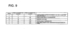
- FIG. 9 An example of the cleaning level which is set by the user is shown in Fig. 9 .
- the cleaning level is divided into five levels in order from the highest level to the lowest level of the necessity of the cleaning operation, and for each of the levels, the reference value of the visibility evaluation value Sn for each recording head and the reference value of the visibility evaluation value St for whole recording heads are set.
- the visibility evaluation value St is "95”, and this value is compared with the reference value set for the cleaning level.
- the reference value of the visibility evaluation value St is "150” and the cleaning operation is not carried out as the next printer operation
- the controller 100 controls the motor drive section 102 and further drives the main scanning motor 5 to move the carriage 2 to the cleaning device 9, and then carrying out cleaning as the next printer operation for all of the recording heads 1a through 1d by the suction caps 9a and the wiping member 9b (2006).
- the defective nozzle occurrence situation and the visibility evaluation value St thereof may be displayed on display section 300.
- the controller 100 compares each of the visibility valuation values Sn for the recording heads 1a through 1d with the comparison reference to determine the next printer operation (2007).
- the respective visibility evaluation values Sn for the recording head 1a is "42", for the recording head 1b is "32", for the recording head 1c is “15”, and for the recording head 1d is "6", and if the cleaning level is set to level 4 by the user, the visibility evaluation values Sn for the recording heads 1a and 1b both exceed the reference value "30" which is set for level 4, and thereby the controller 100 controls the motor drive section 102 and further drives the main scanning motor 5 to move the carriage 2 to the cleaning device 9, and then carrying out cleaning as the next printer operation by the suction caps 9a and the wiping member 9b for the recording heads 1a and 1b whose visibility evaluation values Sn both exceed the reference value (2008).
- the defective nozzle occurrence situation and the visibility evaluation values Sn thereof may be displayed on the display section 300.
- the controller 100 restarts the printing operation and goes to print-continue processing (2009).
- the cleaning level shown in Fig. 9 is set to level 5 so that the cleaning operation is not carried out at all in the defective nozzle occurrence situation of the recording heads 1a through 1d shown in Fig. 6 , and the time loss due to the cleaning operation will not occur.
- the printer operation can adequately controlled depending on the defective nozzle occurrence situation detected by the defective nozzle detector 8, so that the time loss due to the execution of unnecessary cleaning operation will not occur, and thereby the productivity can be improved.
- the cleaning level has been set as levels for each of the recording heads, namely, like the reference values for the visibility evaluation value Sn shown in Fig.9 , the necessity of the cleaning operation can be determined for each of the recording heads 1a through 1d depending on the defective nozzle occurrence situation, so that the unnecessary operation will not be carried out for a defective nozzle in a recording head of a color which is not likely to be visually apparent and the like.
- the cleaning level has been set as levels for the whole recording heads of the plurality of recording heads 1a through 1d all together, namely, like the reference values for the visibility evaluation value St shown in Fig. 9 , the defective nozzle occurrence situation can be determined as a whole in the plurality of recording heads, so that it will be possible to determine more precisely whether the defective nozzles are likely to be visually apparent in the image which is printed by the plurality of recording heads.
- the present invention also includes an inkjet printer with a configuration using a method other than the method as described above that, when a defective nozzle is detected, users confirm the printed image and sets the level at this point as allowable, an inkjet printer having a constitution controlling determination whether or not to carry out the printing stop operation based on this level afterward.
- the setting section is designed to set the level at which cleaning is carried out as the cleaning level setting section 400, but not limited to this, it may be configured to set the level of controlling the execution of other printer operations.
- the setting section may also be configured to simply set the level at which the printing continuation is allowed or disallowed.
- the inkjet printer of the type in which the recording head is mounted in the carriage and moves forward and backward along the main scanning direction is exemplified, but not limited to this, and the recording head may be a line-type recording head that carries out recording at a time across the width of the recording medium.
Landscapes
- Engineering & Computer Science (AREA)
- Quality & Reliability (AREA)
- Ink Jet (AREA)
- Particle Formation And Scattering Control In Inkjet Printers (AREA)
Claims (6)
- Tintenstrahldrucker, umfassend:einen Druckkopf (1) mit einer Vielzahl von Düsen (1 a bis 1 d);eine Detektiervorrichtung (8) für fehlerhafte Düsen zur Überprüfung jeder der Düsen des Druckkopfs, um so fehlerhafte Düsen zu detektieren, aus denen Tintentröpfchen nicht ausgestoßen werden;eine Bestimmungsvorrichtung zum Bestimmen eines Sichtbarkeitsbewertungswertes basierend auf dem Detektionsergebnis der Detektiervorrichtung für fehlerhafte Düsen;eine Betriebssteuervorrichtung zum Steuern des Betriebs des Druckers basierend auf einem Bestimmungsergebnis in der Bestimmungsvorrichtung;dadurch gekennzeichnet, dasseine Anzeigevorrichtung (300) zum Anzeigen des durch die Bestimmungsvorrichtung bestimmten Sichtbarkeitsbewertungswertes; undeine Empfangsvorrichtung zum Empfang einer Eingabe von einem Nutzer, die die Fortführung eines Druckbetriebs basierend auf dem auf der Anzeigevorrichtung angezeigten Ergebnis erlaubt oder nicht erlaubt;die Betriebssteuerungsvorrichtung (100) zum Speichern eines Sichtbarkeitsbewertungswertes zu einem Zeitpunkt des Empfangs einer solchen Eingabe, die die Fortführung des Druckbetriebes erlaubt, eingerichtet ist und so eingerichtet ist, dass,
wenn ein Sichtbarkeitsbewertungswert, der für einen nachfolgenden Druck bestimmt wurde, höher ist, als der gespeicherte Wert, der Druckbetrieb ohne Warten auf eine Eingabe eines Nutzers, die die Fortführung eines Druckbetriebs erlaubt oder nicht erlaubt, fortgeführt wird, und
wenn ein Sichtbarkeitsbewertungswert, der für einen nachfolgenden Druck bestimmt wurde, niedriger ist, als der gespeicherte Wert, der Druckbetrieb unterbrochen wird, bis eine Eingabe, die die Fortführung eines Druckbetriebs erlaubt oder nicht erlaubt, empfangen wird, und dann, wenn eine Eingabe, die die Fortführung des Druckbetriebs erlaubt, empfangen wird, die Betriebssteuerungsvorrichtung den Sichtbarkeitsbewertungswert als gespeicherten Wert speichert. - Tintenstrahldrucker nach Anspruch 1, wobei die
Betriebssteuervorrichtung (100) steuert, ob der Druckbetrieb des Druckers fortgeführt werden soll, oder ob der Reinigungsbetrieb zur Wiederherstellung einer fehlerhaften Düse (1a bis 1d) des Druckkopfes (1) als der Druckerbetrieb durchgeführt werden soll. - Tintenstrahldrucker nach Anspruch 1, wobei eine Situation des Auftretens fehlerhafter Düsen, die in den
Sichtbarkeitsbewertungswert umgewandelt wurde, Information über eine fortlaufende Düsennummer benachbarter fehlerhafter Düsen (1 a bis 1 d) umfasst. - Tintenstrahldrucker nach Anspruch 1 , wobei eine Situation des Auftretens fehlerhafter Düsen, die in den
Sichtbarkeitsbewertungswert umgewandelt wurde, Information über die Farben der aus den Düsen (1 a bis 1 d) des Druckkopfes (1) ausgestoßenen Tintentröpfchen umfasst. - Tintenstrahldrucker nach Anspruch 1 , wobei der Druckkopf (1) eine Vielzahl von Druckköpfen (1a bis 1 d) umfasst, und ein Level einer Situation des Auftretens fehlerhafter Düsen, die in den Sichtbarkeitsbewertungswert umgewandelt wurde, ist das Level für jeden der Druckköpfe.
- Tintenstrahldrucker nach Anspruch 1 , wobei der Druckkopf (1) eine Vielzahl von Druckköpfen (1 a bis 1 d) umfasst, und ein Level des Auftretens fehlerhafter Düsen, die in den
Sichtbarkeitsbewertungswert umgewandelt wurde, ist ein Level für alle der Druckköpfe zusammen.
Applications Claiming Priority (1)
| Application Number | Priority Date | Filing Date | Title |
|---|---|---|---|
| JP2004308737 | 2004-10-22 |
Publications (2)
| Publication Number | Publication Date |
|---|---|
| EP1650032A1 EP1650032A1 (de) | 2006-04-26 |
| EP1650032B1 true EP1650032B1 (de) | 2009-08-12 |
Family
ID=35501119
Family Applications (1)
| Application Number | Title | Priority Date | Filing Date |
|---|---|---|---|
| EP05109660A Expired - Lifetime EP1650032B1 (de) | 2004-10-22 | 2005-10-18 | Tintenstrahldruckgerät mit Erkennung von defekten Düsen |
Country Status (4)
| Country | Link |
|---|---|
| US (1) | US7380899B2 (de) |
| EP (1) | EP1650032B1 (de) |
| AT (1) | ATE439241T1 (de) |
| DE (1) | DE602005015923D1 (de) |
Families Citing this family (20)
| Publication number | Priority date | Publication date | Assignee | Title |
|---|---|---|---|---|
| KR100657335B1 (ko) * | 2005-09-15 | 2006-12-14 | 삼성전자주식회사 | 혼합식 잉크젯 화상형성장치 |
| US8223350B2 (en) * | 2006-02-21 | 2012-07-17 | Xerox Corporation | System and method for minimizing visibility of print defects |
| JP4736128B2 (ja) * | 2006-03-27 | 2011-07-27 | 富士フイルム株式会社 | 印刷装置および印刷システム |
| JP5012182B2 (ja) * | 2006-05-26 | 2012-08-29 | セイコーエプソン株式会社 | 液体滴吐出装置及び液体吐出方法 |
| KR101428479B1 (ko) * | 2007-06-22 | 2014-08-11 | 삼성전자 주식회사 | 잉크젯 화상 형성 장치 및 그 제어 방법 |
| US7815275B2 (en) | 2007-07-27 | 2010-10-19 | Shilin Guo | Interactive visual card-selection process for mitigating light-area banding in a pagewide array |
| JP5130961B2 (ja) * | 2008-03-06 | 2013-01-30 | セイコーエプソン株式会社 | インクジェットプリンタのヘッドクリーニング方法 |
| US20090257077A1 (en) * | 2008-04-15 | 2009-10-15 | Xerox Corporation | Defect avoidance in digital printing |
| KR101507061B1 (ko) * | 2008-07-02 | 2015-03-31 | 삼성전자주식회사 | 잉크젯 화상형성장치 |
| JP2015182337A (ja) * | 2014-03-25 | 2015-10-22 | セイコーエプソン株式会社 | 印刷装置、制御方法、及び、プリントシステム |
| WO2015186463A1 (ja) * | 2014-06-04 | 2015-12-10 | 富士フイルム株式会社 | 画像記録装置及び記録不良の記録素子の検出方法 |
| JP6531053B2 (ja) * | 2016-03-15 | 2019-06-12 | 富士フイルム株式会社 | 印刷装置及びその制御方法並びにプログラム |
| JP7395907B2 (ja) * | 2019-09-25 | 2023-12-12 | ブラザー工業株式会社 | 液体吐出装置及びシステム |
| US11273636B2 (en) | 2019-12-12 | 2022-03-15 | Ricoh Company, Ltd. | Adaptive printhead cleaning |
| JP2023048315A (ja) | 2021-09-28 | 2023-04-07 | 京セラドキュメントソリューションズ株式会社 | 画像形成装置 |
| JP2023048316A (ja) | 2021-09-28 | 2023-04-07 | 京セラドキュメントソリューションズ株式会社 | 画像形成装置 |
| WO2023054360A1 (ja) | 2021-09-28 | 2023-04-06 | 京セラドキュメントソリューションズ株式会社 | 画像形成装置 |
| JP2023064223A (ja) | 2021-10-26 | 2023-05-11 | 京セラドキュメントソリューションズ株式会社 | 画像形成装置 |
| JP2023064222A (ja) | 2021-10-26 | 2023-05-11 | 京セラドキュメントソリューションズ株式会社 | 画像形成装置 |
| US12459264B2 (en) | 2023-03-03 | 2025-11-04 | Ricoh Company, Ltd. | Printhead maintenance for recommending printhead replacement |
Family Cites Families (5)
| Publication number | Priority date | Publication date | Assignee | Title |
|---|---|---|---|---|
| US6089693A (en) * | 1998-01-08 | 2000-07-18 | Xerox Corporation | Pagewidth ink jet printer including multiple pass defective nozzle correction |
| US6000645A (en) * | 1999-01-27 | 1999-12-14 | Bfk Technologies, Inc. | Axial flow, bi-rotor concrete reclaimer |
| US6565179B1 (en) | 1999-02-19 | 2003-05-20 | Hewlett-Packard Company | Method of detecting the end of life of a pen |
| US6847465B1 (en) | 2000-03-17 | 2005-01-25 | Hewlett-Packard Development Company, L.P. | Dynamic ink-jet print mode adjustment |
| JP2003136764A (ja) | 2001-11-06 | 2003-05-14 | Canon Inc | インクジェット記録装置における画像補正方法 |
-
2005
- 2005-10-17 US US11/251,656 patent/US7380899B2/en active Active
- 2005-10-18 DE DE602005015923T patent/DE602005015923D1/de not_active Expired - Lifetime
- 2005-10-18 AT AT05109660T patent/ATE439241T1/de not_active IP Right Cessation
- 2005-10-18 EP EP05109660A patent/EP1650032B1/de not_active Expired - Lifetime
Also Published As
| Publication number | Publication date |
|---|---|
| DE602005015923D1 (de) | 2009-09-24 |
| ATE439241T1 (de) | 2009-08-15 |
| US20060092211A1 (en) | 2006-05-04 |
| US7380899B2 (en) | 2008-06-03 |
| EP1650032A1 (de) | 2006-04-26 |
Similar Documents
| Publication | Publication Date | Title |
|---|---|---|
| US7380899B2 (en) | Inkjet printer | |
| JP4465999B2 (ja) | 印刷装置、吐出検査方法、吐出検査用パターンの形成方法、プログラムおよび印刷システム | |
| JP5227686B2 (ja) | ノズル不良検査方法 | |
| US7101017B2 (en) | Method for testing ejection, printing apparatus, method for forming ejection-test pattern, ejection-test pattern, computer-readable medium, and printing system | |
| JP2000037866A (ja) | プリントヘッドにおける誤動作及び不動作のインクノズルを補償するインクジェットプリンタ及び方法 | |
| USRE41609E1 (en) | Liquid ejection inspecting method, liquid ejection inspector, and image forming apparatus | |
| KR100940026B1 (ko) | 잉크젯 인쇄 장치 및 잉크젯 인쇄 방법 | |
| JP4935029B2 (ja) | インクジェットプリンタ | |
| CN101462422A (zh) | 打印装置以及打印装置的控制方法 | |
| JP2017071067A (ja) | 液体を吐出する装置、プログラム | |
| JP2021049702A (ja) | 液体吐出装置及びシステム | |
| US7503638B2 (en) | Ink jet printing apparatus, and device and method for recovering ejection performance of ink printing apparatus | |
| US7497547B2 (en) | Nozzle cleaning method, nozzle cleaning device, liquid ejection apparatus, printing apparatus and computer-readable medium | |
| US7198349B2 (en) | Method for testing ejection, printing apparatus, method for forming ejection-test pattern, ejection-test pattern, computer-readable medium, and printing system | |
| JP3910133B2 (ja) | ライン型インクジェット記録装置及び記録装置メンテナンスキット | |
| JP2003300313A (ja) | インクジェット式記録装置及びその制御方法 | |
| JP2009208457A (ja) | 画像形成装置 | |
| JP3514235B2 (ja) | インクジェット式記録装置及びインク滴の吐出検査方法 | |
| CN105579235B (zh) | 打印装置以及打印装置的控制方法 | |
| JPH1148463A (ja) | インクジェット記録装置及び記録方式 | |
| JP4583876B2 (ja) | 画像形成装置及びプログラム | |
| JP4658392B2 (ja) | インクジェット記録装置 | |
| JPH09240017A (ja) | インクジェット記録装置 | |
| JP4674671B2 (ja) | インクジェット記録装置及び記録装置メンテナンスキット | |
| JP2009143134A (ja) | 画像記録装置、その装置による清掃方法及びプログラム |
Legal Events
| Date | Code | Title | Description |
|---|---|---|---|
| PUAI | Public reference made under article 153(3) epc to a published international application that has entered the european phase |
Free format text: ORIGINAL CODE: 0009012 |
|
| AK | Designated contracting states |
Kind code of ref document: A1 Designated state(s): AT BE BG CH CY CZ DE DK EE ES FI FR GB GR HU IE IS IT LI LT LU LV MC NL PL PT RO SE SI SK TR |
|
| AX | Request for extension of the european patent |
Extension state: AL BA HR MK YU |
|
| RAP1 | Party data changed (applicant data changed or rights of an application transferred) |
Owner name: KONICA MINOLTA HOLDINGS, INC. |
|
| 17P | Request for examination filed |
Effective date: 20061002 |
|
| AKX | Designation fees paid |
Designated state(s): AT BE BG CH CY CZ DE DK EE ES FI FR GB GR HU IE IS IT LI LT LU LV MC NL PL PT RO SE SI SK TR |
|
| AXX | Extension fees paid |
Extension state: YU Payment date: 20061002 Extension state: MK Payment date: 20061002 Extension state: HR Payment date: 20061002 Extension state: AL Payment date: 20061002 Extension state: BA Payment date: 20061002 |
|
| 17Q | First examination report despatched |
Effective date: 20080619 |
|
| GRAP | Despatch of communication of intention to grant a patent |
Free format text: ORIGINAL CODE: EPIDOSNIGR1 |
|
| GRAS | Grant fee paid |
Free format text: ORIGINAL CODE: EPIDOSNIGR3 |
|
| GRAA | (expected) grant |
Free format text: ORIGINAL CODE: 0009210 |
|
| AK | Designated contracting states |
Kind code of ref document: B1 Designated state(s): AT BE BG CH CY CZ DE DK EE ES FI FR GB GR HU IE IS IT LI LT LU LV MC NL PL PT RO SE SI SK TR |
|
| AX | Request for extension of the european patent |
Extension state: AL BA HR MK YU |
|
| REG | Reference to a national code |
Ref country code: GB Ref legal event code: FG4D |
|
| REG | Reference to a national code |
Ref country code: CH Ref legal event code: EP |
|
| REG | Reference to a national code |
Ref country code: IE Ref legal event code: FG4D |
|
| REF | Corresponds to: |
Ref document number: 602005015923 Country of ref document: DE Date of ref document: 20090924 Kind code of ref document: P |
|
| LTIE | Lt: invalidation of european patent or patent extension |
Effective date: 20090812 |
|
| PG25 | Lapsed in a contracting state [announced via postgrant information from national office to epo] |
Ref country code: SE Free format text: LAPSE BECAUSE OF FAILURE TO SUBMIT A TRANSLATION OF THE DESCRIPTION OR TO PAY THE FEE WITHIN THE PRESCRIBED TIME-LIMIT Effective date: 20090812 Ref country code: IS Free format text: LAPSE BECAUSE OF FAILURE TO SUBMIT A TRANSLATION OF THE DESCRIPTION OR TO PAY THE FEE WITHIN THE PRESCRIBED TIME-LIMIT Effective date: 20091212 Ref country code: FI Free format text: LAPSE BECAUSE OF FAILURE TO SUBMIT A TRANSLATION OF THE DESCRIPTION OR TO PAY THE FEE WITHIN THE PRESCRIBED TIME-LIMIT Effective date: 20090812 Ref country code: ES Free format text: LAPSE BECAUSE OF FAILURE TO SUBMIT A TRANSLATION OF THE DESCRIPTION OR TO PAY THE FEE WITHIN THE PRESCRIBED TIME-LIMIT Effective date: 20091123 Ref country code: LT Free format text: LAPSE BECAUSE OF FAILURE TO SUBMIT A TRANSLATION OF THE DESCRIPTION OR TO PAY THE FEE WITHIN THE PRESCRIBED TIME-LIMIT Effective date: 20090812 Ref country code: AT Free format text: LAPSE BECAUSE OF FAILURE TO SUBMIT A TRANSLATION OF THE DESCRIPTION OR TO PAY THE FEE WITHIN THE PRESCRIBED TIME-LIMIT Effective date: 20090812 |
|
| NLV1 | Nl: lapsed or annulled due to failure to fulfill the requirements of art. 29p and 29m of the patents act | ||
| PG25 | Lapsed in a contracting state [announced via postgrant information from national office to epo] |
Ref country code: SI Free format text: LAPSE BECAUSE OF FAILURE TO SUBMIT A TRANSLATION OF THE DESCRIPTION OR TO PAY THE FEE WITHIN THE PRESCRIBED TIME-LIMIT Effective date: 20090812 Ref country code: NL Free format text: LAPSE BECAUSE OF FAILURE TO SUBMIT A TRANSLATION OF THE DESCRIPTION OR TO PAY THE FEE WITHIN THE PRESCRIBED TIME-LIMIT Effective date: 20090812 Ref country code: LV Free format text: LAPSE BECAUSE OF FAILURE TO SUBMIT A TRANSLATION OF THE DESCRIPTION OR TO PAY THE FEE WITHIN THE PRESCRIBED TIME-LIMIT Effective date: 20090812 Ref country code: PL Free format text: LAPSE BECAUSE OF FAILURE TO SUBMIT A TRANSLATION OF THE DESCRIPTION OR TO PAY THE FEE WITHIN THE PRESCRIBED TIME-LIMIT Effective date: 20090812 |
|
| PG25 | Lapsed in a contracting state [announced via postgrant information from national office to epo] |
Ref country code: BG Free format text: LAPSE BECAUSE OF FAILURE TO SUBMIT A TRANSLATION OF THE DESCRIPTION OR TO PAY THE FEE WITHIN THE PRESCRIBED TIME-LIMIT Effective date: 20091112 Ref country code: PT Free format text: LAPSE BECAUSE OF FAILURE TO SUBMIT A TRANSLATION OF THE DESCRIPTION OR TO PAY THE FEE WITHIN THE PRESCRIBED TIME-LIMIT Effective date: 20091212 |
|
| PG25 | Lapsed in a contracting state [announced via postgrant information from national office to epo] |
Ref country code: CZ Free format text: LAPSE BECAUSE OF FAILURE TO SUBMIT A TRANSLATION OF THE DESCRIPTION OR TO PAY THE FEE WITHIN THE PRESCRIBED TIME-LIMIT Effective date: 20090812 Ref country code: DK Free format text: LAPSE BECAUSE OF FAILURE TO SUBMIT A TRANSLATION OF THE DESCRIPTION OR TO PAY THE FEE WITHIN THE PRESCRIBED TIME-LIMIT Effective date: 20090812 Ref country code: EE Free format text: LAPSE BECAUSE OF FAILURE TO SUBMIT A TRANSLATION OF THE DESCRIPTION OR TO PAY THE FEE WITHIN THE PRESCRIBED TIME-LIMIT Effective date: 20090812 Ref country code: RO Free format text: LAPSE BECAUSE OF FAILURE TO SUBMIT A TRANSLATION OF THE DESCRIPTION OR TO PAY THE FEE WITHIN THE PRESCRIBED TIME-LIMIT Effective date: 20090812 |
|
| PG25 | Lapsed in a contracting state [announced via postgrant information from national office to epo] |
Ref country code: SK Free format text: LAPSE BECAUSE OF FAILURE TO SUBMIT A TRANSLATION OF THE DESCRIPTION OR TO PAY THE FEE WITHIN THE PRESCRIBED TIME-LIMIT Effective date: 20090812 Ref country code: MC Free format text: LAPSE BECAUSE OF NON-PAYMENT OF DUE FEES Effective date: 20091031 |
|
| REG | Reference to a national code |
Ref country code: CH Ref legal event code: PL |
|
| PLBE | No opposition filed within time limit |
Free format text: ORIGINAL CODE: 0009261 |
|
| STAA | Information on the status of an ep patent application or granted ep patent |
Free format text: STATUS: NO OPPOSITION FILED WITHIN TIME LIMIT |
|
| PG25 | Lapsed in a contracting state [announced via postgrant information from national office to epo] |
Ref country code: BE Free format text: LAPSE BECAUSE OF FAILURE TO SUBMIT A TRANSLATION OF THE DESCRIPTION OR TO PAY THE FEE WITHIN THE PRESCRIBED TIME-LIMIT Effective date: 20090812 |
|
| 26N | No opposition filed |
Effective date: 20100517 |
|
| REG | Reference to a national code |
Ref country code: FR Ref legal event code: ST Effective date: 20100630 |
|
| PG25 | Lapsed in a contracting state [announced via postgrant information from national office to epo] |
Ref country code: FR Free format text: LAPSE BECAUSE OF NON-PAYMENT OF DUE FEES Effective date: 20091102 |
|
| PG25 | Lapsed in a contracting state [announced via postgrant information from national office to epo] |
Ref country code: IE Free format text: LAPSE BECAUSE OF NON-PAYMENT OF DUE FEES Effective date: 20091018 Ref country code: CH Free format text: LAPSE BECAUSE OF NON-PAYMENT OF DUE FEES Effective date: 20091031 Ref country code: GR Free format text: LAPSE BECAUSE OF FAILURE TO SUBMIT A TRANSLATION OF THE DESCRIPTION OR TO PAY THE FEE WITHIN THE PRESCRIBED TIME-LIMIT Effective date: 20091113 Ref country code: LI Free format text: LAPSE BECAUSE OF NON-PAYMENT OF DUE FEES Effective date: 20091031 |
|
| PG25 | Lapsed in a contracting state [announced via postgrant information from national office to epo] |
Ref country code: LU Free format text: LAPSE BECAUSE OF NON-PAYMENT OF DUE FEES Effective date: 20091018 |
|
| PG25 | Lapsed in a contracting state [announced via postgrant information from national office to epo] |
Ref country code: HU Free format text: LAPSE BECAUSE OF FAILURE TO SUBMIT A TRANSLATION OF THE DESCRIPTION OR TO PAY THE FEE WITHIN THE PRESCRIBED TIME-LIMIT Effective date: 20100213 |
|
| PG25 | Lapsed in a contracting state [announced via postgrant information from national office to epo] |
Ref country code: TR Free format text: LAPSE BECAUSE OF FAILURE TO SUBMIT A TRANSLATION OF THE DESCRIPTION OR TO PAY THE FEE WITHIN THE PRESCRIBED TIME-LIMIT Effective date: 20090812 |
|
| PG25 | Lapsed in a contracting state [announced via postgrant information from national office to epo] |
Ref country code: CY Free format text: LAPSE BECAUSE OF FAILURE TO SUBMIT A TRANSLATION OF THE DESCRIPTION OR TO PAY THE FEE WITHIN THE PRESCRIBED TIME-LIMIT Effective date: 20090812 |
|
| PGFP | Annual fee paid to national office [announced via postgrant information from national office to epo] |
Ref country code: DE Payment date: 20161011 Year of fee payment: 12 |
|
| REG | Reference to a national code |
Ref country code: DE Ref legal event code: R119 Ref document number: 602005015923 Country of ref document: DE |
|
| PG25 | Lapsed in a contracting state [announced via postgrant information from national office to epo] |
Ref country code: DE Free format text: LAPSE BECAUSE OF NON-PAYMENT OF DUE FEES Effective date: 20180501 |
|
| P01 | Opt-out of the competence of the unified patent court (upc) registered |
Effective date: 20230510 |
|
| PGFP | Annual fee paid to national office [announced via postgrant information from national office to epo] |
Ref country code: IT Payment date: 20230913 Year of fee payment: 19 |
|
| PGFP | Annual fee paid to national office [announced via postgrant information from national office to epo] |
Ref country code: GB Payment date: 20240829 Year of fee payment: 20 |
|
| PG25 | Lapsed in a contracting state [announced via postgrant information from national office to epo] |
Ref country code: IT Free format text: LAPSE BECAUSE OF NON-PAYMENT OF DUE FEES Effective date: 20241018 |
|
| REG | Reference to a national code |
Ref country code: GB Ref legal event code: PE20 Expiry date: 20251017 |