EP1650048B1 - Leicht öffnende Ringordnermechanik - Google Patents
Leicht öffnende Ringordnermechanik Download PDFInfo
- Publication number
- EP1650048B1 EP1650048B1 EP05022927A EP05022927A EP1650048B1 EP 1650048 B1 EP1650048 B1 EP 1650048B1 EP 05022927 A EP05022927 A EP 05022927A EP 05022927 A EP05022927 A EP 05022927A EP 1650048 B1 EP1650048 B1 EP 1650048B1
- Authority
- EP
- European Patent Office
- Prior art keywords
- binder
- trigger
- bar
- ring
- hinge plates
- Prior art date
- Legal status (The legal status is an assumption and is not a legal conclusion. Google has not performed a legal analysis and makes no representation as to the accuracy of the status listed.)
- Expired - Lifetime
Links
Images


Classifications
-
- B—PERFORMING OPERATIONS; TRANSPORTING
- B42—BOOKBINDING; ALBUMS; FILES; SPECIAL PRINTED MATTER
- B42F—SHEETS TEMPORARILY ATTACHED TOGETHER; FILING APPLIANCES; FILE CARDS; INDEXING
- B42F13/00—Filing appliances with means for engaging perforations or slots
- B42F13/16—Filing appliances with means for engaging perforations or slots with claws or rings
- B42F13/20—Filing appliances with means for engaging perforations or slots with claws or rings pivotable about an axis or axes parallel to binding edges
- B42F13/22—Filing appliances with means for engaging perforations or slots with claws or rings pivotable about an axis or axes parallel to binding edges in two sections engaging each other when closed
- B42F13/26—Filing appliances with means for engaging perforations or slots with claws or rings pivotable about an axis or axes parallel to binding edges in two sections engaging each other when closed and locked when so engaged, e.g. snap-action
Definitions
- This invention relates to ring binders for holding paper and the like, and more particularly, a ring binder which is easier to open than conventional ring binders.
- Conventional ring binders employ a pair of thumb or finger operated trigger mechanisms, one located at each end of a "metal".
- the metal includes two or more binder rings connected to a lever movable by the trigger mechanism to open and close the binder.
- the force required to operate the trigger has been relatively substantial.
- the metal is designed to not inadvertently open if a binder is, for example, dropped. Accordingly, conventional metals have been designed to withstand a reasonable amount of force and remain closed.
- the present invention is directed to an easy-open ring metal for a binder holding hole punched sheets of paper or the like.
- the metal includes two or more binder rings each of which comprises two curved ring segments one end of each of which is attached to a hinge plate. The other ends of the respective ring segments mate with each other when the binder is closed, but are separated from each other when the plates are moved to open the binder.
- a movable bar extends from one end of the metal to the other and contacts the hinge plates to move them when the binder is opened.
- a thumb or finger operated trigger is connected to one end of the bar to move the bar.
- the trigger includes a slot in which is fitted a pin attached to one end of the bar. The pin moves in the slot as the trigger is moved by a user of the binder.
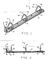
- Fig. 1 is a perspective view of an easy-open binder metal of the present invention in a binder dosed position
- Fig. 2 is a side elevation view of the metal
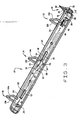
- Fig. 3 is a perspective view of the underside of the metal in the binder closed position
- Fig. 4 is a perspective of the trigger mechanism in the binder closed position
- Fig. 5 is a perspective view of the trigger mechanism in the binder open position.
- Fig. 6 is a view similar to Fig. 3 in the binder open position.
- a "metal" for use in a ring binder is indicated generally 10 and is attached to the spine portion of a binder (not shown) in a conventional manner.
- metal 10 can be of either a metal or a plastic construction, or a combination thereof.
- the metal includes three spaced rings 12, 14, and 16 each of which is comprised of two curved ring segments 12a, 12b, 14a, 14b, and 16a, 16b respectively.
- the rings 12 and 16 are located adjacent each end of the ring metal, while ring 16 is located midway the length thereof.
- Each ring segment has one end attached to a hinge plate 18, 20 respectively.
- the hinge plates are each rectangular plates which extend side-by-side, parallel to each other, substantially the length of the metal.
- the plates are generally flat
- the plates are flexed as shown in Fig. 6, the movement of the plates causes the outer, mating ends of the respective rings to separate from each other and open the binder.
- ring metal 10 could have more or fewer rings without departing from the scope of the invention.
- a cover or shield 22 extends the length of the metal.
- the shield covers the hinge plates and has spaced openings 24 through which the respective ring segments extend.
- a trigger mechanism indicated generally 30, includes a trigger 32 located at one end of the ring metal and a bar 34 attached to the trigger and extending the length of the metal.
- Trigger 32 is rotatably secured to one end of cover 22. As shown in Fig. 3, an end wall 28 of cover 22 has an outwardly extending protrusion 35.
- Trigger 32 has a pivot pin 36 extending transversely across the base of the trigger, and protrusion 35 is curled at its outer end so to enclose an intermediate portion of the pin and secure the trigger to the end of the metal. This means of attachment allows the trigger to pivot about the pin from an upright, generally vertical position, as shown in Figs. 1-4, to a substantially horizontal position as shown in Figs. 5 and 6. Pivot pin 36 therefore provides an axis of rotation for trigger 32.
- the trigger includes a thumb pad or finger pad 38 formed on an upper, inner face of the trigger so a user can apply pressure to the trigger and rotate it about its axis of rotation.
- the upper, inner face of the trigger slopes inwardly from the upper end of the trigger toward end wall 28 of cover 22, so that at its extreme inner reach, this portion of the trigger overlays the upper surface of the cover. (See Figs. 2 and 4.)
- This inner face of the trigger then extends outwardly and downwardly toward the lower, pinned base of the trigger.
- a transversely extending slot 40 is formed in the trigger, adjacent the inner surface thereof.
- the slot is a generally straight slot that extends diagonally from the upper, overhanging portion of trigger 32 toward the lower, pinned base of the trigger.
- an outer end of bar 34 extends from beneath cover 22.
- Two prongs 42 project outwardly from the outer end of bar 34, each prong extending longitudinally from opposite sides of the end of the bar.
- the outer ends of the prongs curl around opposite ends of a pin 44 which extends through slot 40 in trigger 32.
- the length of pin 44 is greater than the length of slot 40 so the respective outer ends of pin 44 project beyond the respective ends of the slot.
- the outer ends of pin 44 are captured in the curled outer ends of the prongs 42 to retain pin 44 in slot 40.
- slot 40 is therefore a "lost motion" slot meaning that initial movement of the trigger does not affect opening of the binder rings. Rather, this begins to occur only after pin 44 has traversed the to the end of the slot.
- hinge plates 18, 20 have a series of correspondingly spaced and shaped openings 46, 48, 50, and 52.
- bar 34 comprises a flat, rectangular shaped bar which extends across the abutting edges of hinge plates 18, 20.
- the bar further has a three raised sections; an inner section 34a at the end of the bar adjacent ring 12, an intermediate section 34b adjacent ring 14, and an outer section 34c adjacent ring 16.
- Each section 34a-34c has a vertical face 54 which projects outwardly from the main body of bar 34, a short flat surface 56 extending rearwardly from the outer end of face 54, and a sloping surface 58 which slopes from the rearward end of surface 56 back to the main body portion of the bar.
- bar 34 When trigger 32 is rotated to close the binder rings, or when the segments of the binder rings are manually pressed together, bar 34 is moved to the left (as viewed in Figs. 3 and 6).
- the sloping surfaces 58 of the bar sections 34a-34c now bear against the left edges of the respective openings, causing hinge plates 18, 20 to rotate outwardly back to their Fig. 3 position in which binder rings are dosed.
- Binder metal 10 of the present invention prevents this from happening.
- the end portion of bar 34 just inwardly of where the prongs 42 begin, has a button or nib 62 extending upwardly from the outer face of the bar.
- a round opening 64 sized for the nib to fit into it, is formed in cover 22.
- the nib seats in this opening and prevents movement of trigger 32 and bar 34 by any incidental forces to which the binder is subjected.
- finger or thumb pressure on pad 38 of the trigger is sufficient to draw the nib away from the opening, as shown in Fig. 5, so the binder can be opened.
Landscapes
- Sheet Holders (AREA)
- Pens And Brushes (AREA)
- Lubricants (AREA)
- Nonmetallic Welding Materials (AREA)
Claims (11)
- Leicht öffnendes Ringmetall (10) für einen Ordner mit mindestens einem Ordnerring (12 - 16), mit zwei Ringsegmenten (12a - 12b, 14a - 14b, 16a - 16b) und einem Paar von Scharnierplatten (18, 20), wobei an einem Ende jeder Platte eines der Segmente (12a - 12b, 14a - 14b, 16a-16b) angebracht ist, wobei das Ringmetall gekennzeichnet ist, durch:eine bewegliche Schiene (34), die sich von einem Ende des Metalls zu dem anderen erstreckt, wobei die Schiene (34) die Scharnierplatten (18, 20) berührt, so dass diese verschoben werden, wenn der Ordner geöffnet werden soll; undeinen Auslöser (32), der mit einem Ende der Schiene (34) verbunden ist, um die Schiene (34) zu verschieben, wenn die Schiene (34) über einen Schlitz (40) mit dem Auslöser (32) verbunden ist, so dass, wenn der Auslöser (32) aus einer ersten Position des geschlossenen Ordners an eine zweite Position des geöffneten Ordners weggezogen wird, sich die Schiene (34) im Verhältnis zu den Scharnierplatten (18, 20) bewegt, so dass bewirkt wird, dass die Scharnierplatten (18, 20) die entsprechenden Segmente (12a - 12b, 14a - 14b, 16a - 16b) der Ordnerringe (12 - 16) voneinander weg drehen und den Ordner öffnen.
- Ringmetall (10) nach Anspruch 1, wobei dieses ferner eine Abdeckung (22) für das Ringmetall (10) aufweist, wobei die Abdeckung (22) darin an einem Ende der Abdeckung, an dem sich der Auslöser (32) befindet, eine Öffnung aufweist, und wobei ein Ansatz (62) an einer Oberfläche der Schiene (34) ausgebildet ist und in der Öffnung sitzt, wenn der Ordner geschlossen ist, um es zu verhindern, dass sich der Auslöser versehentlich bewegt und dadurch bewirkt wird, dass sich der Ordner öffnet.
- Ringmetall (10) nach Anspruch 1, wobei dieses ferner eine Abdeckung (22) für das Ringmetall aufweiset, wobei die Abdeckung eine Endwand (28) aufweist, mit welcher der Auslöser (32) drehbar verbunden ist, um den Ordnerring (12 - 16) zu öffnen und zu schließen.
- Ringmetall (10) nach Anspruch 3, wobei die Endwand (28) der Abdeckung einen auswärts vorstehenden Vorsprung (35) aufweist, und wobei der Auslöser (32) einen Drehzapfen (36) aufweist, der sich transversal über die Basis des Auslösers (32) erstreckt und drehbar mit dem Vorsprung (35) verbunden ist, um es zu ermöglichen, dass sich der Auslöser (32) um dessen Basis dreht, um den Ordnerring zu öffnen und zu schließen.
- Ringmetall (10) nach Anspruch 4, wobei dieses ferner einen Schlitzstift (44) aufweist, der in dem Schlitz (40) installiert ist, und wobei die Schiene (34) mindestens einen Zinken (42) aufweist, der von einem Ende der Schiene (34) auswärts vorsteht, um den Auslöser (32) an der Schiene (34) anzubringen, so dass sich der Schlitzstift (44), wenn sich der Auslöser (32) um dessen Basis dreht, durch den Schlitz (40) bewegt, bis er ein Ende des Schlitzes erreicht, wobei die andauernde Drehbewegung des Auslösers (32) die Schiene (34) in eine Richtung bewegt, so dass eine Öffnung des Ordnerrings bewirkt wird.
- Ringmetall (10) nach Anspruch 5, wobei die Schiene (34) eine Mehrzahl erhöhter Abschnitte (34a - 34c) aufweist, die sich im Verhältnis zu den Scharnierplatten (18, 20) bewegen, wenn der Auslöser (32) gedreht wird, wobei die erhöhten Abschnitte auf die Scharnierplatten (18, 20) wirken, um sie in eine Richtung zum Öffnen des Ordnerrings zu bewegen.
- Ringmetall (10) nach Anspruch 6, wobei die Schiene (34) eine Reihe von erhöhten Abschnitten (34a, 34c) aufweist, die an einer Seite der Scharnierplatten (18, 20) lagern, wenn sich der Auslöser (32) an dessen geschlossenen Ordnerringposition befindet, wobei die Abschnitte (34a, 34c) aus dem Kontakt mit den Scharnierplatten (18, 20) bewegt werden, wenn der Auslöser (32) gedreht wird, um es zu ermöglichen, dass sich die Scharnierplatten (18, 20) bewegen.
- Ringmetall (10) nach Anspruch 7, wobei die Scharnierplatten (18, 20) eine Reihe räumlich getrennter Öffnungen (46 - 52) aufweisen, in welche die erhöhten Abschnitte (34a - 34c) der Schiene (34) gezogen werden, wenn sich der Auslöser (32) dreht, wodurch es ermöglicht wird, dass sich die Scharnierplatten (18, 20) bewegen.
- Ringmetall (10) nach Anspruch 8, wobei mindestens einer der erhöhten Abschnitte (34a, 34c) der Schiene (34) eine darin ausgebildete Kerbe (60) aufweist, die die Bewegung der Scharnierplatten (18, 20) erleichtert, wenn der erhöhte Abschnitt in eine der Öffnungen (46 - 52) gezogen wird.
- Ringmetall (10) nach Anspruch 9, wobei das Drehen des Auslösers (32) in eine Richtung zum Schließen des Ordnerrings (12 - 16) bewirkt, dass sich die Schiene (34) in die entgegengesetzte Richtung bewegt und die Scharnierplatten (18, 20) wieder zurück an die Ausgangsposition des geschlossenen Ordnerrings führt.
- Ringmetall (10) nach Anspruch 1, wobei eine Mehrzahl von Ordnerringen (12 - 16) entlang der Länge des Ringmetalls räumlich getrennt angeordnet ist, wobei jeder Ordnerring zwei Ringsegmente (12a - 12b, 14a - 14b, 16a - 16b) umfasst.
Applications Claiming Priority (2)
| Application Number | Priority Date | Filing Date | Title |
|---|---|---|---|
| US62082204P | 2004-10-21 | 2004-10-21 | |
| US11/100,679 US7530755B2 (en) | 2004-10-21 | 2005-04-07 | Easy open ring binder |
Publications (2)
| Publication Number | Publication Date |
|---|---|
| EP1650048A1 EP1650048A1 (de) | 2006-04-26 |
| EP1650048B1 true EP1650048B1 (de) | 2007-12-12 |
Family
ID=35636901
Family Applications (1)
| Application Number | Title | Priority Date | Filing Date |
|---|---|---|---|
| EP05022927A Expired - Lifetime EP1650048B1 (de) | 2004-10-21 | 2005-10-20 | Leicht öffnende Ringordnermechanik |
Country Status (5)
| Country | Link |
|---|---|
| US (1) | US7530755B2 (de) |
| EP (1) | EP1650048B1 (de) |
| AT (1) | ATE380678T1 (de) |
| CA (1) | CA2523899C (de) |
| DE (1) | DE602005003752D1 (de) |
Families Citing this family (16)
| Publication number | Priority date | Publication date | Assignee | Title |
|---|---|---|---|---|
| US7404685B2 (en) | 2004-12-30 | 2008-07-29 | World Wide Stationery Manufacturing Company, Limited | Ring binder mechanism spring biased to a locked position when ring members close |
| US7661899B2 (en) | 2005-03-22 | 2010-02-16 | World Wide Stationery Mfg. Co., Ltd. | Lever for a ring binder mechanism |
| USD585935S1 (en) | 2007-01-05 | 2009-02-03 | World Wide Stationery Mfg. Co., Ltd. | Rectilinear binder ring |
| US10118431B2 (en) * | 2006-07-06 | 2018-11-06 | World Wide Stationery Mfg. Co., Ltd. | Ring for ring binder mechanism |
| US8047737B2 (en) | 2006-09-27 | 2011-11-01 | World Wide Stationery Mfg. Co., Ltd. | Ring binder mechanism |
| US7731441B2 (en) | 2006-09-27 | 2010-06-08 | World Wide Stationery Mfg. Co., Ltd. | Ring binder mechanism |
| CN102126374B (zh) | 2010-01-14 | 2013-10-30 | 国际文具制造厂有限公司 | 具有双时间缓冲的致动器的环形活页夹机构 |
| USD745602S1 (en) | 2011-12-12 | 2015-12-15 | Kam Hold (Macao Commercial Offshore) Limited | Ring binder mechanism having a convex central rib |
| US8899866B2 (en) | 2012-04-28 | 2014-12-02 | World Wide Stationary Mfg. Co. Ltd. | Ring binder mechanism with self-locking actuator |
| US9409436B2 (en) * | 2013-01-24 | 2016-08-09 | R.R. Donnelley & Sons Company | Binder apparatus |
| US9522561B2 (en) * | 2013-08-27 | 2016-12-20 | World Wide Stationery Mfg. Co., Ltd. | Ring binder mechanism |
| US9511617B2 (en) | 2013-10-31 | 2016-12-06 | World Wide Stationary Mfg. Co., Ltd. | Ring binder mechanism |
| US9102187B1 (en) | 2014-02-19 | 2015-08-11 | Chung Tin International, Inc. | Ring binder mechanism |
| US9827808B1 (en) * | 2017-03-03 | 2017-11-28 | Sau Fung YIP | Control component for a single detent binder |
| USD949969S1 (en) * | 2019-11-19 | 2022-04-26 | Ccl Label, Inc. | Binder mechanism |
| USD1058666S1 (en) * | 2022-11-30 | 2025-01-21 | Youzhong Zhang | Ring binder mechanism |
Family Cites Families (24)
| Publication number | Priority date | Publication date | Assignee | Title |
|---|---|---|---|---|
| US566717A (en) * | 1896-08-25 | Lettel pile | ||
| US651254A (en) * | 1899-02-14 | 1900-06-05 | Armin Krah | Letter-file. |
| US924647A (en) * | 1904-03-03 | 1909-06-15 | Thomas R Eddy | Loose-leaf ledger. |
| US842851A (en) * | 1904-12-05 | 1907-02-05 | Charles G Boden | Binder. |
| US974831A (en) * | 1909-07-08 | 1910-11-08 | Tengwall Company | Loose-leaf binder. |
| US1157154A (en) * | 1915-04-07 | 1915-10-19 | Joseph De Falco | Observation apparatus. |
| US1667744A (en) * | 1919-09-02 | 1928-05-01 | Frank C Skiles | Loose-leaf binder |
| US2103307A (en) * | 1933-06-26 | 1937-12-28 | Wilson Jones Co | Loose-leaf binder |
| US2364859A (en) * | 1943-07-01 | 1944-12-12 | Lichtenstein Leo | Loose-leaf binder |
| US2612169A (en) * | 1948-06-14 | 1952-09-30 | Wilson Jones Co | Slidably actuated loose-leaf binder |
| US3077888A (en) * | 1958-07-21 | 1963-02-19 | Gen Binding Corp | Slide lock for a binding element |
| NL280196A (de) * | 1961-07-14 | |||
| US3995961A (en) * | 1970-02-18 | 1976-12-07 | Jerome S. Serchuck | Ring binder |
| US4571108A (en) * | 1982-11-26 | 1986-02-18 | Kurt Vogl | Locking ring binder mechanism with control slide |
| US4566817A (en) * | 1984-01-16 | 1986-01-28 | Barrett Jr Arthur M | Ring binder |
| US6276862B1 (en) * | 1999-09-15 | 2001-08-21 | Acco Brands, Inc. | Binder mechanism |
| US6364558B1 (en) | 2000-03-31 | 2002-04-02 | World Wide Stationery Mfg. Co., Ltd. | Ring binder having actuating lever with cushion member |
| US6840695B2 (en) * | 2000-04-25 | 2005-01-11 | Esselte Leitz Gmbh & Co Kg | Ring-binder mechanism |
| US6758621B2 (en) * | 2001-08-03 | 2004-07-06 | World Wide Stationery Manufacturing Company, Ltd. | Ring binder mechanism |
| US7296946B2 (en) * | 2001-11-30 | 2007-11-20 | Microsoft Corporation | Ring binder mechanism |
| US6749357B2 (en) * | 2001-11-30 | 2004-06-15 | World Wide Stationery Manufacturing Company, Limited | Ring binder mechanism |
| US6974273B2 (en) * | 2002-07-16 | 2005-12-13 | World Wide Stationery Manufacturing Company Limited | Ring binder |
| US7549817B2 (en) * | 2002-12-18 | 2009-06-23 | World Wide Stationery Mfg. Co., Ltd. | Ready lock ring binder mechanism |
| US6916134B2 (en) * | 2003-05-22 | 2005-07-12 | Hong Kong Stationery Manufacturing Co., Ltd. | Safety ring binder having sliding actuators |
-
2005
- 2005-04-07 US US11/100,679 patent/US7530755B2/en not_active Expired - Fee Related
- 2005-10-20 AT AT05022927T patent/ATE380678T1/de not_active IP Right Cessation
- 2005-10-20 EP EP05022927A patent/EP1650048B1/de not_active Expired - Lifetime
- 2005-10-20 DE DE602005003752T patent/DE602005003752D1/de not_active Expired - Lifetime
- 2005-10-20 CA CA2523899A patent/CA2523899C/en not_active Expired - Fee Related
Also Published As
| Publication number | Publication date |
|---|---|
| CA2523899C (en) | 2012-01-03 |
| EP1650048A1 (de) | 2006-04-26 |
| DE602005003752D1 (de) | 2008-01-24 |
| US7530755B2 (en) | 2009-05-12 |
| ATE380678T1 (de) | 2007-12-15 |
| US20060088364A1 (en) | 2006-04-27 |
| HK1093186A1 (zh) | 2007-02-23 |
| CA2523899A1 (en) | 2006-04-21 |
Similar Documents
| Publication | Publication Date | Title |
|---|---|---|
| US7491006B2 (en) | Easy open ring binder | |
| CA2523899C (en) | Easy open ring binder | |
| US6293722B1 (en) | Binder Mechanism | |
| EP0808727A1 (de) | Ring-Ordner | |
| WO1995025641A1 (en) | Ring binding tool | |
| MX2008011243A (es) | Mecanismo de carpeta de argollas con alojamiento polimerico y barra de desplazamiento. | |
| AU1677902A (en) | Device for retaining a stack of papers in a file | |
| US20070140780A1 (en) | Ring binder mechanism | |
| US20090285623A1 (en) | Locking ring metal | |
| CN100564067C (zh) | 文件夹机构 | |
| JP3955868B2 (ja) | 書類等の綴じ具 | |
| US20070134052A1 (en) | Ring binder mechanism | |
| US20070134055A1 (en) | Ring binder mechanism | |
| US20090041531A1 (en) | Lever-arch type file mechanism | |
| EP2006117A1 (de) | Ringordnerartiger Ablagemechanismus | |
| CN101224683A (zh) | 杠杆夹机构 | |
| HK1093186B (en) | Easy open ring binder | |
| CN100488783C (zh) | 易开启环式活页夹 | |
| JP2603916Y2 (ja) | 綴 具 | |
| HK1126171B (en) | Easy open ring binder | |
| US7461994B2 (en) | Twist lock ring binder | |
| EP2014481B1 (de) | Ringordnerartiger Ablagemechanismus | |
| JPH05139085A (ja) | フアイル機構バインダ | |
| KR20080064702A (ko) | 아치형-레버를 갖춘 서류철 기구 | |
| CN101224685A (zh) | 杠杆夹机构 |
Legal Events
| Date | Code | Title | Description |
|---|---|---|---|
| PUAI | Public reference made under article 153(3) epc to a published international application that has entered the european phase |
Free format text: ORIGINAL CODE: 0009012 |
|
| AK | Designated contracting states |
Kind code of ref document: A1 Designated state(s): AT BE BG CH CY CZ DE DK EE ES FI FR GB GR HU IE IS IT LI LT LU LV MC NL PL PT RO SE SI SK TR |
|
| AX | Request for extension of the european patent |
Extension state: AL BA HR MK YU |
|
| 17P | Request for examination filed |
Effective date: 20060529 |
|
| AKX | Designation fees paid |
Designated state(s): AT BE BG CH CY CZ DE DK EE ES FI FR GB GR HU IE IS IT LI LT LU LV MC NL PL PT RO SE SI SK TR |
|
| GRAP | Despatch of communication of intention to grant a patent |
Free format text: ORIGINAL CODE: EPIDOSNIGR1 |
|
| GRAS | Grant fee paid |
Free format text: ORIGINAL CODE: EPIDOSNIGR3 |
|
| GRAA | (expected) grant |
Free format text: ORIGINAL CODE: 0009210 |
|
| AK | Designated contracting states |
Kind code of ref document: B1 Designated state(s): AT BE BG CH CY CZ DE DK EE ES FI FR GB GR HU IE IS IT LI LT LU LV MC NL PL PT RO SE SI SK TR |
|
| REG | Reference to a national code |
Ref country code: GB Ref legal event code: FG4D |
|
| REG | Reference to a national code |
Ref country code: CH Ref legal event code: EP |
|
| REG | Reference to a national code |
Ref country code: IE Ref legal event code: FG4D |
|
| REF | Corresponds to: |
Ref document number: 602005003752 Country of ref document: DE Date of ref document: 20080124 Kind code of ref document: P |
|
| PG25 | Lapsed in a contracting state [announced via postgrant information from national office to epo] |
Ref country code: CH Free format text: LAPSE BECAUSE OF FAILURE TO SUBMIT A TRANSLATION OF THE DESCRIPTION OR TO PAY THE FEE WITHIN THE PRESCRIBED TIME-LIMIT Effective date: 20071212 Ref country code: LI Free format text: LAPSE BECAUSE OF FAILURE TO SUBMIT A TRANSLATION OF THE DESCRIPTION OR TO PAY THE FEE WITHIN THE PRESCRIBED TIME-LIMIT Effective date: 20071212 Ref country code: SE Free format text: LAPSE BECAUSE OF FAILURE TO SUBMIT A TRANSLATION OF THE DESCRIPTION OR TO PAY THE FEE WITHIN THE PRESCRIBED TIME-LIMIT Effective date: 20080312 |
|
| PG25 | Lapsed in a contracting state [announced via postgrant information from national office to epo] |
Ref country code: PL Free format text: LAPSE BECAUSE OF FAILURE TO SUBMIT A TRANSLATION OF THE DESCRIPTION OR TO PAY THE FEE WITHIN THE PRESCRIBED TIME-LIMIT Effective date: 20071212 Ref country code: LT Free format text: LAPSE BECAUSE OF FAILURE TO SUBMIT A TRANSLATION OF THE DESCRIPTION OR TO PAY THE FEE WITHIN THE PRESCRIBED TIME-LIMIT Effective date: 20071212 Ref country code: LV Free format text: LAPSE BECAUSE OF FAILURE TO SUBMIT A TRANSLATION OF THE DESCRIPTION OR TO PAY THE FEE WITHIN THE PRESCRIBED TIME-LIMIT Effective date: 20071212 Ref country code: NL Free format text: LAPSE BECAUSE OF FAILURE TO SUBMIT A TRANSLATION OF THE DESCRIPTION OR TO PAY THE FEE WITHIN THE PRESCRIBED TIME-LIMIT Effective date: 20071212 Ref country code: SI Free format text: LAPSE BECAUSE OF FAILURE TO SUBMIT A TRANSLATION OF THE DESCRIPTION OR TO PAY THE FEE WITHIN THE PRESCRIBED TIME-LIMIT Effective date: 20071212 Ref country code: FI Free format text: LAPSE BECAUSE OF FAILURE TO SUBMIT A TRANSLATION OF THE DESCRIPTION OR TO PAY THE FEE WITHIN THE PRESCRIBED TIME-LIMIT Effective date: 20071212 |
|
| NLV1 | Nl: lapsed or annulled due to failure to fulfill the requirements of art. 29p and 29m of the patents act | ||
| REG | Reference to a national code |
Ref country code: CH Ref legal event code: PL |
|
| PG25 | Lapsed in a contracting state [announced via postgrant information from national office to epo] |
Ref country code: AT Free format text: LAPSE BECAUSE OF FAILURE TO SUBMIT A TRANSLATION OF THE DESCRIPTION OR TO PAY THE FEE WITHIN THE PRESCRIBED TIME-LIMIT Effective date: 20071212 |
|
| PG25 | Lapsed in a contracting state [announced via postgrant information from national office to epo] |
Ref country code: IS Free format text: LAPSE BECAUSE OF FAILURE TO SUBMIT A TRANSLATION OF THE DESCRIPTION OR TO PAY THE FEE WITHIN THE PRESCRIBED TIME-LIMIT Effective date: 20080412 Ref country code: CZ Free format text: LAPSE BECAUSE OF FAILURE TO SUBMIT A TRANSLATION OF THE DESCRIPTION OR TO PAY THE FEE WITHIN THE PRESCRIBED TIME-LIMIT Effective date: 20071212 Ref country code: ES Free format text: LAPSE BECAUSE OF FAILURE TO SUBMIT A TRANSLATION OF THE DESCRIPTION OR TO PAY THE FEE WITHIN THE PRESCRIBED TIME-LIMIT Effective date: 20080323 |
|
| PG25 | Lapsed in a contracting state [announced via postgrant information from national office to epo] |
Ref country code: RO Free format text: LAPSE BECAUSE OF FAILURE TO SUBMIT A TRANSLATION OF THE DESCRIPTION OR TO PAY THE FEE WITHIN THE PRESCRIBED TIME-LIMIT Effective date: 20071212 Ref country code: BE Free format text: LAPSE BECAUSE OF FAILURE TO SUBMIT A TRANSLATION OF THE DESCRIPTION OR TO PAY THE FEE WITHIN THE PRESCRIBED TIME-LIMIT Effective date: 20071212 Ref country code: SK Free format text: LAPSE BECAUSE OF FAILURE TO SUBMIT A TRANSLATION OF THE DESCRIPTION OR TO PAY THE FEE WITHIN THE PRESCRIBED TIME-LIMIT Effective date: 20071212 |
|
| EN | Fr: translation not filed | ||
| PG25 | Lapsed in a contracting state [announced via postgrant information from national office to epo] |
Ref country code: PT Free format text: LAPSE BECAUSE OF FAILURE TO SUBMIT A TRANSLATION OF THE DESCRIPTION OR TO PAY THE FEE WITHIN THE PRESCRIBED TIME-LIMIT Effective date: 20080512 |
|
| PLBE | No opposition filed within time limit |
Free format text: ORIGINAL CODE: 0009261 |
|
| STAA | Information on the status of an ep patent application or granted ep patent |
Free format text: STATUS: NO OPPOSITION FILED WITHIN TIME LIMIT |
|
| PG25 | Lapsed in a contracting state [announced via postgrant information from national office to epo] |
Ref country code: FR Free format text: LAPSE BECAUSE OF FAILURE TO SUBMIT A TRANSLATION OF THE DESCRIPTION OR TO PAY THE FEE WITHIN THE PRESCRIBED TIME-LIMIT Effective date: 20080926 Ref country code: DE Free format text: LAPSE BECAUSE OF FAILURE TO SUBMIT A TRANSLATION OF THE DESCRIPTION OR TO PAY THE FEE WITHIN THE PRESCRIBED TIME-LIMIT Effective date: 20080313 Ref country code: DK Free format text: LAPSE BECAUSE OF FAILURE TO SUBMIT A TRANSLATION OF THE DESCRIPTION OR TO PAY THE FEE WITHIN THE PRESCRIBED TIME-LIMIT Effective date: 20071212 |
|
| 26N | No opposition filed |
Effective date: 20080915 |
|
| PG25 | Lapsed in a contracting state [announced via postgrant information from national office to epo] |
Ref country code: GR Free format text: LAPSE BECAUSE OF FAILURE TO SUBMIT A TRANSLATION OF THE DESCRIPTION OR TO PAY THE FEE WITHIN THE PRESCRIBED TIME-LIMIT Effective date: 20080313 |
|
| PG25 | Lapsed in a contracting state [announced via postgrant information from national office to epo] |
Ref country code: BG Free format text: LAPSE BECAUSE OF FAILURE TO SUBMIT A TRANSLATION OF THE DESCRIPTION OR TO PAY THE FEE WITHIN THE PRESCRIBED TIME-LIMIT Effective date: 20080312 Ref country code: EE Free format text: LAPSE BECAUSE OF FAILURE TO SUBMIT A TRANSLATION OF THE DESCRIPTION OR TO PAY THE FEE WITHIN THE PRESCRIBED TIME-LIMIT Effective date: 20071212 |
|
| PG25 | Lapsed in a contracting state [announced via postgrant information from national office to epo] |
Ref country code: MC Free format text: LAPSE BECAUSE OF NON-PAYMENT OF DUE FEES Effective date: 20081031 |
|
| PG25 | Lapsed in a contracting state [announced via postgrant information from national office to epo] |
Ref country code: CY Free format text: LAPSE BECAUSE OF FAILURE TO SUBMIT A TRANSLATION OF THE DESCRIPTION OR TO PAY THE FEE WITHIN THE PRESCRIBED TIME-LIMIT Effective date: 20071212 |
|
| PG25 | Lapsed in a contracting state [announced via postgrant information from national office to epo] |
Ref country code: IE Free format text: LAPSE BECAUSE OF NON-PAYMENT OF DUE FEES Effective date: 20081020 |
|
| PG25 | Lapsed in a contracting state [announced via postgrant information from national office to epo] |
Ref country code: LU Free format text: LAPSE BECAUSE OF NON-PAYMENT OF DUE FEES Effective date: 20081020 Ref country code: HU Free format text: LAPSE BECAUSE OF FAILURE TO SUBMIT A TRANSLATION OF THE DESCRIPTION OR TO PAY THE FEE WITHIN THE PRESCRIBED TIME-LIMIT Effective date: 20080613 |
|
| PG25 | Lapsed in a contracting state [announced via postgrant information from national office to epo] |
Ref country code: TR Free format text: LAPSE BECAUSE OF FAILURE TO SUBMIT A TRANSLATION OF THE DESCRIPTION OR TO PAY THE FEE WITHIN THE PRESCRIBED TIME-LIMIT Effective date: 20071212 |
|
| PG25 | Lapsed in a contracting state [announced via postgrant information from national office to epo] |
Ref country code: IT Free format text: LAPSE BECAUSE OF NON-PAYMENT OF DUE FEES Effective date: 20081031 |
|
| PGFP | Annual fee paid to national office [announced via postgrant information from national office to epo] |
Ref country code: GB Payment date: 20101025 Year of fee payment: 6 |
|
| GBPC | Gb: european patent ceased through non-payment of renewal fee |
Effective date: 20121020 |
|
| PG25 | Lapsed in a contracting state [announced via postgrant information from national office to epo] |
Ref country code: GB Free format text: LAPSE BECAUSE OF NON-PAYMENT OF DUE FEES Effective date: 20121020 |