EP1650141A2 - Method for mounting a storage rack structure by using an elevator apparatus - Google Patents
Method for mounting a storage rack structure by using an elevator apparatus Download PDFInfo
- Publication number
- EP1650141A2 EP1650141A2 EP20050109862 EP05109862A EP1650141A2 EP 1650141 A2 EP1650141 A2 EP 1650141A2 EP 20050109862 EP20050109862 EP 20050109862 EP 05109862 A EP05109862 A EP 05109862A EP 1650141 A2 EP1650141 A2 EP 1650141A2
- Authority
- EP
- European Patent Office
- Prior art keywords
- construction
- platform
- building
- units
- vertical
- Prior art date
- Legal status (The legal status is an assumption and is not a legal conclusion. Google has not performed a legal analysis and makes no representation as to the accuracy of the status listed.)
- Withdrawn
Links
Images


Classifications
-
- B—PERFORMING OPERATIONS; TRANSPORTING
- B66—HOISTING; LIFTING; HAULING
- B66F—HOISTING, LIFTING, HAULING OR PUSHING, NOT OTHERWISE PROVIDED FOR, e.g. DEVICES WHICH APPLY A LIFTING OR PUSHING FORCE DIRECTLY TO THE SURFACE OF A LOAD
- B66F11/00—Lifting devices specially adapted for particular uses not otherwise provided for
- B66F11/04—Lifting devices specially adapted for particular uses not otherwise provided for for movable platforms or cabins, e.g. on vehicles, permitting workmen to place themselves in any desired position for carrying out required operations
Definitions
- the present invention relates to handling-storage facilities using pallet trucks or the like in particular of heavy manufactured products, such as concrete products, for example borders, blocks, pavers, etc.
- Such products are manufactured industrially at a high rate by means of automated molding production units which deliver a very large number of products which must be dried in superimposed shelving systems served by moving robotic apparatus. on rails.
- These machines are programmed by PLCs to support, with the aid of a multi-fork carriage, a plurality of trays one above the other and each carrying one or more concrete products for conveying them from the molding unit. at pre-determined storage locations, so that the products dry, then resume them for evacuation.
- Modern shelving tends toward more and more advanced optimization, leading to an increase in storage capacity taking up the minimum space. This leads to the realization of shelving comprising a large number of storage stages with the minimum of lost space.
- These shelves generally comprise posts fixed to the ground along said transverse parallel tracks, which are obtained by back-to-back assembly of two sections having a section of overall "U" shape around a console of at least one frame.
- Each frame also includes horizontal profiles protruding in the corridors delimited between the rows of poles, these horizontal profiles thus defining in each corridor, a number of storage stages for supporting trays carrying one or more concrete products.
- Figure 1 shows a rack structure being developed according to a method of the prior art.
- the operator after having fastened to the ground two posts P 1 , P 2 having evenly spaced bores, fixes a horizontal element EH connecting the bores arranged lowest on these posts P 1 , P 2 . After having fixed this horizontal element, the operator relies on this element EH to repeat the operation on the upper stage until all the holes C of each of the columns are connected to each other.
- the operator although equipped with a harness is likely to fall thus putting his health in danger.
- the current methods of mounting on site involves firstly the realization on the ground of modules each comprising posts assembled around brackets of frames arranged at regular intervals along these poles, the number of these intervals being a function of the number of desired shelving.
- This pre-assembly on the ground, manual and tedious for the workers is done without tightening the bolts used for connecting the different parts.
- Each module thus obtained is then hoisted by means of a hoist such as a crane for example and placed on its mounting site to be fixed to the ground.
- a worker equipped with a safety harness then climbs to the upper end of this module to connect it to at least one module juxtaposed along the service path and tighten all the bolts.
- this mounting technique is not optimized. It is therefore incompatible with the economic imperatives aiming at an accelerated construction of storage structures.
- the objective of the present invention is therefore to propose a method for mounting a simple storage structure in its design and in its operating mode allowing a rapid assembly of this structure and its roof, and an improvement of the conditions of worker intervention while reducing the risks to their health.
- This method advantageously allows the construction of storage structure having vertical assembled modules perfectly aligned and parallel to each other by simultaneous positioning of operators and building elements.
- the invention relates to a method of mounting a storage structure comprising service channels (V1, V2, V3, ...) parallel to each other and orthogonal to a main channel Vp disposed in a direction Y.
- This method of mounting a storage structure can advantageously be based on a railroad rack service device, whose main and lateral service railroad tracks have a very precise leveling and alignment, such as that described in FIG. applicant's patent application EP1260458.
- Construction unit means an assembly comprising at least two posts. These posts are advantageously poles type IPE, UAP single or double, tubes, or any profile having the particularity to take the charges. It may also be masonry elements, for example posts made of concrete. Preferably, the building unit has four posts.
- the lifting device has a platform comprising longitudinal extension elements of this platform to modulate its length, so as to adapt the lifting device to the considered building unit.
- construction element means horizontal sections such as bars or preassembled elements such as frames. These building elements are, for illustrative purposes, made of steel, concrete or reinforced concrete.
- the invention also relates to a lifting device for implementing the method as described above.
- This lifting device is a device for moving and positioning at least one operator for construction or maintenance work, such as the construction of a heavy product storage structure.
- This lifting device comprises a mobile frame in a plane of displacement, a platform intended to receive this operator and his tooling and means for controlling the vertical displacement of this platform relative to the chassis, the platform having an axis longitudinal.
- each of these fine displacement means comprises second motorized drive means connected by a gear system to a threaded rod and an optical encoder for controlling the movement of the corresponding support member.
- These support members may be cylindrical rods movable in rotation about axes perpendicular to the longitudinal axis of the platform to adjust the position along this axis of the construction or maintenance elements.
- This lifting device is advantageously used in the method for mounting a storage structure described above because it makes it possible to position in height, in complete safety and in optimal working conditions at the same time one or more operators, their tools and at least two sets of construction elements or maintenance such as frames, horizontal profiles or other .... It also allows to work simultaneously on a first and a second building units arranged on each side of said platform along the track on which the chassis is moving.
- these building units each comprise a profile at each end, two assembled posts interposed between these profiles, the profiles and the assembled posts being connected in their upper part to a frame without clamping, these units can come by example in support of sets of frames in step a).
- this device is adapted to circulate on rails and comprises at least one temporary anchoring device to ensure its stability during the displacement of the platform in the event of difficult external conditions (wind, etc.) .
- This anchoring device comprises a pair of jaws mounted on an axis, driving means for moving said jaws towards each other so as to pinch or release the bead of a rail and means of self-locking. centering this pair of jaws on the central axis of the running surface of this rail.
- Each jaw may comprise at least one lug pinching the rail of the flange.
- each pair of jaws is always centered on the median axis of the running surface of the rail. This prevents the pins from striking the rail joints.
- Figure 2 there is shown a device for moving and positioning at least one operator for construction or maintenance work simultaneously with the construction or maintenance elements.
- This device comprises a mobile frame 1 in a horizontal plane.
- This frame 1 is in this particular embodiment adapted to circulate on rails 2, but it may also include tire wheels for traveling on roads for example. It is also advantageously motorized to ensure its movement autonomously but it can also be pulled by a motor vehicle such as a tractor.
- the device comprises a platform 3 for receiving the operator and his tool and means for controlling the displacement of this platform relative to the frame along a vertical axis.
- the platform 3 can thus be raised or lowered to position an operator near a mounting or maintenance area with his tools and assembly parts such as bolts, screws, etc.
- the means for controlling the displacement of the platform with respect to the chassis comprise first motorized drive means for driving the platform along two parallel and vertical rack track sections 4. Guiding means, for example rollers, ensure the displacement of the platform along these sections. However, other means for controlling the displacement of the platform relative to the frame are possible, it may be pneumatic or hydraulic actuating means or scissors for example.
- the device may include means for manually or automatically blocking the platform in an elevated position.
- the platform 3 comprises in a known manner a floor 5 along which the operator can move and side walls 6 such as barriers to protect the operator when the platform is in a raised position with respect to the operator. frame.
- the platform 3 has a median longitudinal axis 7 and preferably has a rectangular shape.
- the platform 3 may comprise longitudinal extension elements 8 to modulate its length. These elements when they are fixed in position on the main platform 3 have their longitudinal axis coincident with that of the main platform and the lateral barriers 6 of these elements form a continuity with those of the main platform. The length of the floor 5 is thus increased and thus the operative working area of the operator.
- These extension members have at the base of their frame supporting a floor, and in the direction of their longitudinal axis, support arms at one end and recesses at the other end. The recesses are intended to receive the support arms of the main platform or an extension element already secured to this main platform. Locking means such as bolts enable these extension elements to be locked in position.
- Platform 3 can also include ways to modulate its width. It is then slides guided in translation by slides.
- the platform 3 also comprises support members 9 which are removable and separate from construction or maintenance elements. These separate support members 9 are placed on either side of this platform with respect to its longitudinal axis 7 so that these construction or maintenance elements 10 are roughly placed in the mounting position with the operator during the vertical displacement of the platform 3. These support members 9 are made of a material capable of withstanding heavy loads without undergoing deformation and are therefore made, for example steel. In the particular embodiment of Figure 2, the platform 3 comprises two pairs of separate support members 9, each of these pairs being placed on either side of the platform relative to its longitudinal axis. 7. The support members 9 further comprise means for temporarily fixing construction or maintenance elements to move these elements safely.
- Fine displacement means 11 make it possible to independently control the vertical displacement of each of these support members 9 so as to accurately position the construction or maintenance elements 10.
- Each of these fine displacement means 11 comprises by example of the second motorized drive means, for example a motor, connected by a gear system to a threaded rod and an optical encoder to control the movement of said corresponding support member.
- these fine displacement means may alternatively comprise pneumatic or hydraulic actuation means.
- the support members 9 are cylindrical rods rotatable about axes perpendicular to the longitudinal axis 7 of the platform to adjust the position of the construction or maintenance elements 10 along this axis 7. It it is then possible to adjust the position of these construction elements 10 when the device for moving and positioning at least one operator is locked in position along the service road for example by temporary anchoring means 12 so as to ensure the safety of operators in a high position.
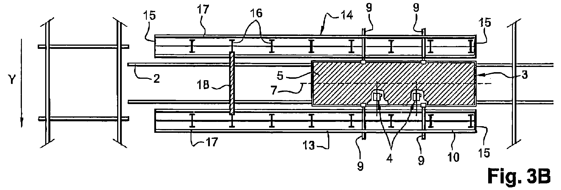
- FIG 3 there is shown a partial view of a storage structure obtained according to the method of the invention in a particular embodiment.
- This storage structure comprises an area of the shelving having ground attachment points for fixing posts and aligned in X and Y. In each corridor between these attachment points are arranged on the ground two parallel rails of a service road, V1, V2, V3, etc., orthogonal to a so-called main track Vp consisting of two horizontal rails arranged in the Y direction and slightly lower than the ground of the shelving area.
- the device for moving and positioning at least one operator is particularly intended to circulate on the service channels V1, V2, V3, etc .... to allow the construction of the storage structure.
- articulated support members 20 at the upper end of columns 16 assembled to receive a roof.
- the posts are formed for example from steel profiles having a global shape "U”, for example profiles "C”.
- U for example profiles "C”.
- Figure 4 shows a partial view of a storage structure in a particular embodiment.
- Heavy manufactured products such as concrete products, for example, taken from the group consisting of borders, blocks and blocks are arranged in shelves for drying therein. When these manufactured products have dried, they are evacuated using a multi-fork truck.
- the parallel channels of services V1, V2, V3, ... assigned to the rack are visible.
- the structure comprises means for ensuring its verticality 22 and articulated support elements 20 for receiving a roof placed at the upper end of assembled posts.
- Figure 5 shows a temporary anchoring device 12 in a particular embodiment. It comprises a pair of jaws 23 mounted on an axis 24, which are displaced by a screw 25 inverted driven by an electric motor. By this sliding of the two jaws 23 in the same plane on the part B, we obtain a pinch or loosening of the flange of the rail 2. The training of the jaws 23 is obtained by reversing the direction of rotation of the screw.
- the anchoring device also comprises a first piece A integral with the wheel support.
- the self-centering means are such that a second piece B is sliding on the piece A and that a fixed point is positioned on the piece A 26 and two fixed points 27,28 on the piece B.
Landscapes
- Engineering & Computer Science (AREA)
- Structural Engineering (AREA)
- Life Sciences & Earth Sciences (AREA)
- Geology (AREA)
- Mechanical Engineering (AREA)
- Conveying And Assembling Of Building Elements In Situ (AREA)
- Warehouses Or Storage Devices (AREA)
Abstract
L'invention concerne un procédé pour le montage d'une structure de stockage. Selon l'invention, on place en position verticale une unité de construction (13, 14) d'un seul côté, ou de chaque côté, le long d'une voie de desserte considérée, puis on fixe la partie inférieure de ces unités (13,14) à des points de fixation au sol. On distribue dans un plan vertical un ensemble d'éléments de construction (10,17) au moyen d'un dispositif élévateur en fixant chaque élément de construction à l'unité de construction correspondante pour obtenir une unité assemblée verticale. On répète ces étapes en juxtaposant le long de la voie de desserte considérée une unité de construction à chacune desdites unités assemblées verticales et en reliant lesdites unités ainsi juxtaposées jusqu'à avoir atteint la dimension longitudinale finale de ladite structure de stockage. Puis, on répète l'ensemble de ces étapes pour chacune des voies jusqu'à avoir atteint la dimension transversale finale de la structure de stockage.

Description
La présente invention se rapporte aux installations de manutention-stockage à l'aide de transpalettes ou analogues notamment de produits manufacturés lourds, tels que des produits en béton, par exemple des bordures, des blocs, des pavés, etc....The present invention relates to handling-storage facilities using pallet trucks or the like in particular of heavy manufactured products, such as concrete products, for example borders, blocks, pavers, etc.
De tels produits sont fabriqués industriellement à cadence élevée à l'aide d'unités de fabrication par moulage automatisé qui délivrent un nombre très important de produits qui doivent subir un séchage qui s'opère dans des systèmes de rayonnage superposés desservis par des appareils robotisés circulant sur des rails. Ces engins sont programmés par des automates pour prendre en charge à l'aide d'un chariot multi-fourches une pluralité de plateaux les uns au dessus des autres et portant chacun un ou plusieurs produits en béton pour les acheminer de l'unité de moulage à des emplacements de stockage pré-déterminés, afin que les produits sèchent, puis les reprendre pour les évacuer.Such products are manufactured industrially at a high rate by means of automated molding production units which deliver a very large number of products which must be dried in superimposed shelving systems served by moving robotic apparatus. on rails. These machines are programmed by PLCs to support, with the aid of a multi-fork carriage, a plurality of trays one above the other and each carrying one or more concrete products for conveying them from the molding unit. at pre-determined storage locations, so that the products dry, then resume them for evacuation.
Ces déplacements s'opèrent sur un système de voies ferrées comprenant une voie principale desservant une pluralité de voies parallèles transversales affectées au rayonnage.These displacements occur on a railroad system comprising a main track serving a plurality of transverse parallel channels assigned to the rack.
Les rayonnages modernes tendent vers une optimisation de plus en plus poussée conduisant à une augmentation des capacités de stockage occupant le minimum d'espace. Ceci amène à réaliser des rayonnages comprenant un nombre important d'étages de stockage avec le minimum d'espace perdu.Modern shelving tends toward more and more advanced optimization, leading to an increase in storage capacity taking up the minimum space. This leads to the realization of shelving comprising a large number of storage stages with the minimum of lost space.
Ces rayonnages comportent généralement des poteaux fixés au sol le long desdites voies parallèles transversales, lesquels sont obtenus par assemblage dos à dos de deux profilés ayant une section de forme globale en "U" autour d'une console d'au moins un cadre. Chaque cadre comprend par ailleurs des profilés horizontaux faisant saillie dans les couloirs délimités entre les rangées de poteaux, ces profilés horizontaux définissant ainsi dans chaque couloir, un certain nombre d'étages de stockage servant au support des plateaux portant un ou plusieurs produits en béton.These shelves generally comprise posts fixed to the ground along said transverse parallel tracks, which are obtained by back-to-back assembly of two sections having a section of overall "U" shape around a console of at least one frame. Each frame also includes horizontal profiles protruding in the corridors delimited between the rows of poles, these horizontal profiles thus defining in each corridor, a number of storage stages for supporting trays carrying one or more concrete products.
La Figure 1 représente une structure de rayonnage en cours d'élaboration selon un procédé de l'art antérieur. L'opérateur après avoir fixé au sol deux poteaux P1, P2 présentant des perçages régulièrement espacés, fixe un élément horizontal EH reliant les perçages disposés le plus bas sur ces poteaux P1, P2. Après avoir fixé cet élément horizontal, l'opérateur prend appui sur cet élément EH pour répéter l'opération à l'étage supérieure jusqu'à avoir relié l'ensemble des perçages C de chacun des poteaux entre eux. Outre la pénibilité, l'opérateur bien qu'équipé d'un harnais est susceptible de chuter mettant ainsi sa santé en danger.Figure 1 shows a rack structure being developed according to a method of the prior art. The operator after having fastened to the ground two posts P 1 , P 2 having evenly spaced bores, fixes a horizontal element EH connecting the bores arranged lowest on these posts P 1 , P 2 . After having fixed this horizontal element, the operator relies on this element EH to repeat the operation on the upper stage until all the holes C of each of the columns are connected to each other. In addition to the harshness, the operator although equipped with a harness is likely to fall thus putting his health in danger.
Alternativement, les méthodes actuelles de montage sur site implique dans un premier temps la réalisation au sol de modules comprenant chacun des poteaux assemblés autour de consoles de cadres disposées à intervalles réguliers le long de ces poteaux, le nombre de ces intervalles étant fonction du nombre de rayonnages souhaités. Ce pré-assemblage au sol, manuel et fastidieux pour les travailleurs est réalisé sans serrage des boulons servant à la liaison des différentes pièces. Chaque module ainsi obtenu est ensuite hissé au moyen d'un engin de levage tel qu'une grue par exemple et placé sur son site de montage pour être fixé au sol. Un travailleur équipé de harnais de sécurité grimpe alors à l'extrémité supérieure de ce module pour le relier à au moins un module juxtaposé le long de la voie de desserte et serrer l'ensemble des boulons. Outre les risques pour l'opérateur s'élevant à des hauteurs de rayonnages pouvant atteindre couramment une dizaine de mètres au dessus du sol, cette technique de montage est peu optimisée. Elle est donc peu compatible avec les impératifs économiques visant à une construction accélérée des structures de stockage.Alternatively, the current methods of mounting on site involves firstly the realization on the ground of modules each comprising posts assembled around brackets of frames arranged at regular intervals along these poles, the number of these intervals being a function of the number of desired shelving. This pre-assembly on the ground, manual and tedious for the workers is done without tightening the bolts used for connecting the different parts. Each module thus obtained is then hoisted by means of a hoist such as a crane for example and placed on its mounting site to be fixed to the ground. A worker equipped with a safety harness then climbs to the upper end of this module to connect it to at least one module juxtaposed along the service path and tighten all the bolts. In addition to the risks for the operator rising to rack heights that can currently reach ten meters above the ground, this mounting technique is not optimized. It is therefore incompatible with the economic imperatives aiming at an accelerated construction of storage structures.
L'objectif de la présente invention est donc de proposer un procédé pour le montage d'une structure de stockage simple dans sa conception et dans son mode opératoire permettant un montage rapide de cette structure et de sa toiture, et une amélioration des conditions d'intervention du ou des travailleurs tout en réduisant les risques pour leur santé. Ce procédé permet avantageusement la construction de structure de stockage présentant des modules assemblés verticaux parfaitement alignés et parallèles entre eux par une mise en position simultanée des opérateurs et des éléments de construction.The objective of the present invention is therefore to propose a method for mounting a simple storage structure in its design and in its operating mode allowing a rapid assembly of this structure and its roof, and an improvement of the conditions of worker intervention while reducing the risks to their health. This method advantageously allows the construction of storage structure having vertical assembled modules perfectly aligned and parallel to each other by simultaneous positioning of operators and building elements.
A cet effet, l'invention concerne un procédé de montage d'une structure de stockage comprenant des voies de desserte (V1, V2, V3, ...) parallèles entre elles et orthogonales à une voie principale Vp disposée selon une direction Y.To this end, the invention relates to a method of mounting a storage structure comprising service channels (V1, V2, V3, ...) parallel to each other and orthogonal to a main channel Vp disposed in a direction Y.
Selon l'invention, partant de ladite première voie de desserte V1, on réalise les étapes suivantes :
- a) on place en position verticale une unité de construction d'un seul côté, ou parallèlement de chaque côté, le long de la voie de desserte considérée, ces unités de construction ayant une partie supérieure et une partie inférieure,
- b) on fixe la partie inférieure de chacune de ces unités à des points de fixation au sol,
- c) on distribue dans un plan vertical un ensemble d'éléments de construction au moyen d'un dispositif élévateur en fixant chaque élément de construction à l'unité de construction correspondante pour obtenir une unité assemblée verticale,
- le dispositif élévateur comprenant un châssis mobile, une plate-forme et des moyens pour commander le déplacement vertical de ladite plate-forme par rapport à ce châssis, la plate-forme ayant un axe longitudinal,
- la plate-forme comprenant des organes de support amovibles et séparés pour recevoir les éléments de construction, lesdits organes étant placés d'un seul côté ou de part et d'autre de cette plate-forme par rapport à l'axe longitudinal, et des moyens de déplacement fin pour commander indépendamment le déplacement vertical de chacun de ces organes de support de manière à positionner avec précision les éléments de construction,
- d) on répète les étapes a) à c) en juxtaposant le long de cette voie de desserte considérée une unité de construction à chacune des unités assemblées verticales ainsi réalisées et en reliant les unités ainsi juxtaposées jusqu'à avoir atteint la dimension longitudinale finale de la structure de stockage,
- e) on répète chacune des étapes a) à d) pour au moins chacune des voies impaires V2n+1 avec n entier positif, jusqu'à avoir atteint la dimension finale de la structure de stockage le long de la voie principale Vp.
- (a) a construction unit is placed in a vertical position on one side only, or parallel to each side, along the service road in question, such building units having an upper part and a lower part,
- b) the lower part of each of these units is fixed to ground attachment points,
- c) distributing a set of building elements in a vertical plane by means of a lifting device by fastening each building element to the corresponding building unit to obtain a vertical assembled unit,
- the elevator device comprising a movable frame, a platform and means for controlling the vertical displacement of said platform relative to said frame, the platform having a longitudinal axis,
- the platform comprising removable and separate support members for receiving the construction elements, said members being placed on one side or on either side of this platform with respect to the longitudinal axis, and fine moving means for independently controlling the vertical displacement of each of said support members so as to accurately position the construction elements,
- d) repeating steps a) to c) by juxtaposing along this service route considered a construction unit to each of the vertical assembled units thus produced and connecting the units thus juxtaposed until reaching the final longitudinal dimension of the storage structure,
- e) repeating each of steps a) to d) for at least each of the odd channels V2n + 1 with n positive integer until reaching the final dimension of the storage structure along the main channel Vp.
Ce procédé de montage d'une structure de stockage peut avantageusement s'appuyer sur un dispositif de voies ferrées de desserte de rayonnages, dont les voies ferrées de desserte, principales et latérales présentent un nivellement et un alignement très précis, tel que celui décrit dans la demande de brevet EP1260458 du demandeur.
On entend par "unité de construction", un ensemble comportant au moins deux poteaux. Ces poteaux sont avantageusement des poteaux de type IPE, UAP simple ou double, des tubes, ou tout profilé ayant la particularité de reprendre les charges. Il peut encore s'agir d'éléments maçonnés, par exemple des poteaux réalisés en béton.
De préférence, l'unité de construction comporte quatre poteaux. Le dispositif élévateur présente une plateforme comprenant des éléments d'extension longitudinale de cette plate-forme pour moduler sa longueur, et ce de manière à adapter le dispositif élévateur à l'unité de construction considérée.
On entend par "élément de construction", des profilés horizontaux tels que des barres ou des éléments préassemblés tels que des cadres. Ces éléments de construction sont, à titre purement illustratif, réalisés en acier, en béton ou en béton armé.This method of mounting a storage structure can advantageously be based on a railroad rack service device, whose main and lateral service railroad tracks have a very precise leveling and alignment, such as that described in FIG. applicant's patent application EP1260458.
"Construction unit" means an assembly comprising at least two posts. These posts are advantageously poles type IPE, UAP single or double, tubes, or any profile having the particularity to take the charges. It may also be masonry elements, for example posts made of concrete.
Preferably, the building unit has four posts. The lifting device has a platform comprising longitudinal extension elements of this platform to modulate its length, so as to adapt the lifting device to the considered building unit.
The term "construction element" means horizontal sections such as bars or preassembled elements such as frames. These building elements are, for illustrative purposes, made of steel, concrete or reinforced concrete.
Dans différents modes de réalisation, la présente invention concerne également les caractéristiques suivantes qui devront être considérées isolément ou selon toutes leurs combinaisons techniquement possibles :
- ayant simultanément positionné de chaque côté de la voie de desserte considérée une unité de construction, on relie, avant l'étape c), ces unités de construction dans leur partie supérieure par au moins un élément de liaison et on fixe cet élément de liaison à ces unités,
- ayant positionné de chaque côté de la voie de desserte considérée une unité de construction, on relie avant l'étape c) relative à la dernière unité de construction considérée, ces unités de construction dans leur partie supérieure par au moins un élément de liaison et on fixe cet élément de liaison à ces unités de construction,
- l'élément de liaison comprend une traverse parallèle à la voie principale Vp,
- on dispose de plus diagonalement des traverses pour relier les unités de construction entre elles,
- chaque unité de construction comprend au moins deux poteaux comportant chacun des corbeaux ou des perçages disposés à intervalles réguliers ou non le long desdits poteaux,
- lesdits éléments de construction sont des cadres ou des profilés horizontaux.
- les moyens pour commander le déplacement de la plate-forme par rapport au châssis sont choisis dans le groupe comprenant un mécanisme du type à ciseaux, des bras articulés ou télescopiques, ou encore au moins deux tronçons de voie à crémaillère verticaux, ladite plate-forme comprenant dans ce dernier cas des moyens de guidage pour assurer son déplacement le long desdits tronçons,
- chacun desdits moyens de déplacement fin comprend des deuxièmes moyens d'entraînement motorisés reliés par un système d'engrenages à une tige filetée et un codeur optique pour contrôler le déplacement de l'organe de support correspondant.
- having simultaneously positioned a construction unit on each side of the service road in question, these building units are connected to the upper part by at least one connecting element before step c) and this connecting element is fixed to these units,
- having positioned on each side of the service road considered a building unit, is connected before step c) relative to the last building unit considered, these building units in their upper part by at least one connecting element and sets this link element to these building units,
- the connecting element comprises a cross member parallel to the main track Vp,
- diagonals are more diagonally available to connect the building units to each other,
- each building unit comprises at least two posts each having crunches or bores arranged at regular intervals or not along said posts,
- said construction elements are frames or horizontal sections.
- the means for controlling the displacement of the platform with respect to the frame are chosen from the group comprising a scissor-type mechanism, articulated or telescopic arms, or at least two vertical rack-and-pinion track sections, said platform comprising in the latter case guide means to ensure its movement along said sections,
- each of said fine moving means comprises second motorized drive means connected by a gear system to a threaded rod and an optical encoder for controlling movement of the corresponding support member.
L'invention concerne également un dispositif élévateur pour la mise en oeuvre du procédé tel que décrit précédemment. Ce dispositif élévateur est un dispositif pour déplacer et positionner au moins un opérateur pour des travaux de construction ou de maintenance, tels que la construction d'une structure de stockage de produits lourds. Ce dispositif élévateur comprend un châssis mobile dans un plan de déplacement, une plate-forme destinée à recevoir cet opérateur et son outillage et des moyens pour commander le déplacement vertical de cette plate-forme par rapport au châssis, la plate-forme ayant un axe longitudinal.The invention also relates to a lifting device for implementing the method as described above. This lifting device is a device for moving and positioning at least one operator for construction or maintenance work, such as the construction of a heavy product storage structure. This lifting device comprises a mobile frame in a plane of displacement, a platform intended to receive this operator and his tooling and means for controlling the vertical displacement of this platform relative to the chassis, the platform having an axis longitudinal.
Selon l'invention, la plate-forme comprend:
- des organes de support amovibles et séparés d'éléments de construction, ces organes étant placés d'un seul côté ou de part et d'autre de la plate-forme par rapport à l'axe longitudinal de sorte que ces éléments de construction ou de maintenance soient placés grossièrement en position de montage avec l'opérateur lors du déplacement vertical de la plateforme,
- des moyens de déplacement fin pour commander indépendamment le déplacement vertical de chacun de ces organes de support de manière à positionner avec précision les éléments de construction ou de maintenance.
- removable and separate support members of construction elements, these members being placed on one side or on either side of the platform with respect to the longitudinal axis so that these elements of construction or maintenance are placed roughly in the mounting position with the operator during the vertical movement of the platform,
- fine displacement means for independently controlling the vertical displacement of each of said support members so as to accurately position the construction or maintenance elements.
Dans un mode de réalisation préférentiel, chacun de ces moyens de déplacement fin comprend des deuxièmes moyens d'entraînement motorisés reliés par un système d'engrenages à une tige filetée et un codeur optique pour contrôler le déplacement de l'organe de support correspondant.In a preferred embodiment, each of these fine displacement means comprises second motorized drive means connected by a gear system to a threaded rod and an optical encoder for controlling the movement of the corresponding support member.
Ces organes de support peuvent être des tiges cylindriques mobiles en rotation autour d'axes perpendiculaires à l'axe longitudinal de la plate-forme pour ajuster la position le long de cet axe des éléments de construction ou de maintenance.These support members may be cylindrical rods movable in rotation about axes perpendicular to the longitudinal axis of the platform to adjust the position along this axis of the construction or maintenance elements.
Ce dispositif élévateur est avantageusement mis en oeuvre dans le procédé pour le montage d'une structure de stockage décrit plus haut car il permet de positionner en hauteur, en toute sécurité et dans des conditions de travail optimales à la fois un ou plusieurs opérateurs, leurs outils et au moins deux ensembles d'éléments de construction ou de maintenance tels que des cadres, des profilés horizontaux ou autres.... Il permet de surcroît de travailler simultanément sur une première et une deuxième unités de construction disposées de chaque coté de ladite plate-forme le long de la voie sur laquelle se déplace le châssis. Dans le cas particulier où ces unités de construction comprennent chacune un profilé à chacune de leur extrémité, deux poteaux assemblés intercalés entre ces profilés, les profilés et les poteaux assemblés étant reliés dans leur partie supérieure à un cadre sans serrage, ces unités peuvent venir par exemple en appui sur des ensembles de cadres à l'étape a).This lifting device is advantageously used in the method for mounting a storage structure described above because it makes it possible to position in height, in complete safety and in optimal working conditions at the same time one or more operators, their tools and at least two sets of construction elements or maintenance such as frames, horizontal profiles or other .... It also allows to work simultaneously on a first and a second building units arranged on each side of said platform along the track on which the chassis is moving. In the particular case where these building units each comprise a profile at each end, two assembled posts interposed between these profiles, the profiles and the assembled posts being connected in their upper part to a frame without clamping, these units can come by example in support of sets of frames in step a).
Dans un mode réalisation préféré, ce dispositif est adapté pour circuler sur des rails et comprend au moins un dispositif d'ancrage temporaire pour assurer sa stabilité lors du déplacement de la plate-forme en cas de conditions extérieures difficiles (vent, ...). Ce dispositif d'ancrage comprend une paire de mâchoires montées sur un axe, des moyens d'entraînement pour déplacer lesdites mâchoires l'une vers l'autre de manière à pincer ou relâcher le boudin d'un rail et des moyens d'auto-centrage de cette paire de mâchoires sur l'axe médian de la surface de roulement de ce rail. Chaque mâchoire peut comprendre au moins un ergot venant pincer le boudin du rail.In a preferred embodiment, this device is adapted to circulate on rails and comprises at least one temporary anchoring device to ensure its stability during the displacement of the platform in the event of difficult external conditions (wind, etc.) . This anchoring device comprises a pair of jaws mounted on an axis, driving means for moving said jaws towards each other so as to pinch or release the bead of a rail and means of self-locking. centering this pair of jaws on the central axis of the running surface of this rail. Each jaw may comprise at least one lug pinching the rail of the flange.
Ainsi même en cas de variations de la largeur du boudin des rails sur lesquelles circule le châssis du dispositif pour déplacer et positionner au moins un opérateur, chaque paire de mâchoires est toujours centrée sur l'axe médian de la surface de roulement du rail. On évite ainsi que les ergots ne puissent heurter les joints de rail.Thus, even in the case of variations in the width of the flange of the rails on which the chassis of the device travels to move and position at least one operator, each pair of jaws is always centered on the median axis of the running surface of the rail. This prevents the pins from striking the rail joints.
Dans différents modes de réalisation possibles, l'invention sera décrite plus en détail en référence aux dessins annexés dans lesquels :
- la figure 1 représente schématiquement une structure de stockage de l'art antérieur en cours de construction ; la Fig. 1a) est une vue agrandie de la partie supérieure d'un de ces poteaux ;
- la figure 2 est une représentation schématique du dispositif pour déplacer et positionner au moins un opérateur pour des travaux de construction ou de maintenance selon un mode de réalisation particulier de l'invention;
- la figure 3 représente schématiquement une vue partielle de profil d'une structure métallique de stockage en cours de construction selon un mode de réalisation particulier du procédé de l'invention (Fig. 3 a) et une vue partielle de dessus de ladite structure (Fig. 3 b);
- la figure 4 est une représentation schématique d'une vue partielle d'une structure métallique de stockage dans un autre mode de réalisation de l'invention ;
- la figure 5 est une représentation schématique du dispositif d'ancrage temporaire ;
- Figure 1 schematically shows a storage structure of the prior art under construction; FIG. 1a) is an enlarged view of the upper part of one of these posts;
- Figure 2 is a schematic representation of the device for moving and positioning at least one operator for construction or maintenance work according to a particular embodiment of the invention;
- 3 schematically represents a partial profile view of a metal storage structure being constructed according to a particular embodiment of the method of the invention (FIG 3 a) and a partial view from above of said structure (FIG. 3 (b);
- Figure 4 is a schematic representation of a partial view of a metal storage structure in another embodiment of the invention;
- Figure 5 is a schematic representation of the temporary anchor device;
Sur la figure 2, on a représenté un dispositif pour déplacer et positionner au moins un opérateur pour des travaux de construction ou de maintenance simultanément avec les éléments de construction ou de maintenance.In Figure 2, there is shown a device for moving and positioning at least one operator for construction or maintenance work simultaneously with the construction or maintenance elements.
Ce dispositif comprend un châssis mobile 1 dans un plan horizontal. Ce châssis 1 est dans ce mode de réalisation particulier adapté pour circuler sur des rails 2 mais il peut également comporter des roues à pneus pour des déplacements sur des routes par exemple. Il est de plus avantageusement motorisé pour assurer son déplacement de manière autonome mais il peut également être tiré par un véhicule motorisé tel qu'un engin tracteur.This device comprises a
Le dispositif comprend une plate-forme 3 destinée à recevoir l'opérateur et son outillage et des moyens pour commander le déplacement de cette plate-forme par rapport au châssis le long d'un axe vertical. La plate-forme 3 peut ainsi être élever ou abaisser pour positionner un opérateur à proximité d'une zone de montage ou de maintenance avec ses outils et des pièces d'assemblage telles que des boulons, vis, ...The device comprises a
Les moyens pour commander le déplacement de la plate-forme par rapport au châssis comprennent des premiers moyens d'entraînement motorisés pour entraîner la plate-forme le long de deux tronçons 4 de voie à crémaillère parallèles et verticaux. Des moyens de guidage, par exemple des galets, assurent le déplacement de la plate-forme le long de ces tronçons. Cependant, d'autres moyens pour commander le déplacement de la plate-forme par rapport au châssis sont possibles, il peut s'agir de moyens d'actionnement pneumatique ou hydraulique ou encore des ciseaux par exemple. Le dispositif peut comprendre des moyens pour bloquer manuellement ou automatiquement la plate-forme en position élevée.The means for controlling the displacement of the platform with respect to the chassis comprise first motorized drive means for driving the platform along two parallel and vertical
La plate-forme 3 comprend de manière connue un plancher 5 le long duquel peut se déplacer l'opérateur et des parois latérales 6 telles que des barrières pour assurer la protection de cet opérateur lorsque la plate-forme se trouve en position élevée par rapport au châssis. La plate-forme 3 présente un axe longitudinal médian 7 et présente de préférence une forme rectangulaire.The
La plate-forme 3 peut comprendre des éléments d'extension longitudinale 8 pour moduler sa longueur. Ces éléments lorsqu'ils sont fixés en position sur la plate-forme principale 3 ont leur axe longitudinal confondu avec celui de la plateforme principale et les barrières latérales 6 de ces éléments forment une continuité avec celles de la plate-forme principale. La longueur du plancher 5 est ainsi augmentée et de ce fait la zone opérationnelle de travail de l'opérateur. Ces éléments d'extension comportent à la base de leur bâti supportant un plancher, et dans la direction de leur axe longitudinal, des bras-supports à une extrémité et des évidements à l'autre extrémité. Les évidements sont destinés à recevoir les bras-supports de la plate-forme principale ou d'un élément d'extension déjà arrimé à cette plate-forme principale. Des moyens de blocage tels que des boulons permettent de bloquer en position ces éléments d'extension. La plate-forme 3 peut aussi comprendre des moyens pour moduler sa largeur. Il s'agit alors de coulisseaux guidés en translation par des glissières.The
La plate-forme 3 comprend également des organes de support 9 amovibles et séparés d'éléments de construction ou de maintenance. Ces organes de support 9 distincts sont placés de part et d'autre de cette plate-forme par rapport à son axe longitudinal 7 de sorte que ces éléments de construction ou de maintenance 10 sont placés grossièrement en position de montage avec l'opérateur lors du déplacement vertical de la plate-forme 3. Ces organes de support 9 sont réalisés dans un matériau apte à supporter des charges lourdes sans subir de déformation et sont donc réalisés, par exemple en acier. Dans le mode de réalisation particulier de la figure 2, la plate-forme 3 comprend deux paires d'organes de support 9 séparés, chacune de ces paires étant placée de part et d'autre de la plate-forme par rapport à son axe longitudinal 7. Les organes de support 9 comprennent par ailleurs des moyens de fixation temporaire d'éléments de construction ou de maintenance pour déplacer ces éléments en sécurité.The
Des moyens de déplacement fin 11 (figure 3a) permettent de commander indépendamment le déplacement vertical de chacun de ces organes de support 9 de manière à positionner avec précision les éléments de construction ou de maintenance 10. Chacun de ces moyens de déplacement fin 11 comprend par exemple des deuxièmes moyens d'entraînement motorisés, un moteur par exemple, reliés par un système d'engrenages à une tige filetée et un codeur optique pour contrôler le déplacement dudit organe de support correspondant. Cependant ces moyens de déplacement fin peuvent alternativement comprendre des moyens d'actionnement pneumatique ou hydraulique.Fine displacement means 11 (FIG. 3a) make it possible to independently control the vertical displacement of each of these
Avantageusement, les organes de support 9 sont des tiges cylindriques mobiles en rotation autour d'axes perpendiculaires à l'axe longitudinal 7 de la plate-forme pour ajuster la position des éléments de construction ou de maintenance 10 le long de cet axe 7. Il est alors possible d'ajuster la position de ces éléments de construction 10 lorsque le dispositif pour déplacer et positionner au moins un opérateur est bloqué en position le long de la voie de desserte par exemple par des moyens d'ancrage temporaire 12 de manière à assurer la sécurité des opérateurs en position élevée.Advantageously, the
Sur la figure 3, on a représenté une vue partielle d'une structure de stockage obtenue selon le procédé de l'invention dans un mode de réalisation particulier. Cette structure de stockage comprend une zone des rayonnages comportant des points d'attache au sol destinés à la fixation de poteaux et alignés en X et Y. Dans chaque couloir entre ces points d'attache sont disposés sur le sol deux rails parallèles d'une voie de desserte, V1, V2, V3, etc...., orthogonale à une voie dite principale Vp constituée de deux rails horizontaux disposés selon la direction Y et en léger contre-bas par rapport au sol de la zone des rayonnages. Le dispositif pour déplacer et positionner au moins un opérateur est notamment destiné à circuler sur les voies de desserte V1, V2, V3, etc.... pour permettre la construction de la structure de stockage. Un chariot portant de manière fixe deux tronçons de rail (non représentés) orthogonaux aux rails de la voie principale Vp et de même écartement que celui des rails des voies de desserte V1, V2, V3, ... est destiné à permettre le déplacement du dispositif pour déplacer et positionner au moins un opérateur d'une voie de desserte à une autre.In Figure 3, there is shown a partial view of a storage structure obtained according to the method of the invention in a particular embodiment. This storage structure comprises an area of the shelving having ground attachment points for fixing posts and aligned in X and Y. In each corridor between these attachment points are arranged on the ground two parallel rails of a service road, V1, V2, V3, etc., orthogonal to a so-called main track Vp consisting of two horizontal rails arranged in the Y direction and slightly lower than the ground of the shelving area. The device for moving and positioning at least one operator is particularly intended to circulate on the service channels V1, V2, V3, etc .... to allow the construction of the storage structure. A carriage fixedly carrying two rail sections (not shown) orthogonal to the rails of the main track Vp and of the same spacing as that of the rails of the service channels V1, V2, V3,... Is intended to allow the movement of the device for moving and positioning at least one operator from one serving path to another.
Selon le procédé de l'invention, on part de la première voie de desserte V1 et on réalise dans un premier temps les étapes suivantes :
- a) on place parallèlement en position verticale et de chaque coté le long de la voie de desserte considérée une première unité de
construction 13 et une deuxième unité deconstruction 14, ces unités de construction ayant une partie supérieure et une partie inférieure, et un axe longitudinal parallèle à ladite voie. Ces unités deconstruction chacune un profilé 15 à chacune de leur extrémité, deux poteaux assemblés 16 étant intercalés entreces profilés 15, les profilés 15 et les poteaux assemblés 16 étant reliés dans leur partie supérieure àun cadre 17 sans serrage, - b) on fixe sans serrage, par exemple par boulonnage, les unités de
construction - c) on relie les première et deuxième unités de
construction liaison 18 et on fixe sans serrage cet élément deliaison 18 aux première et deuxième unités de construction, - d) on distribue simultanément de la partie supérieure des première et deuxième unités de
construction cadres 17 en fixant sans serrage chaquecadre aux poteaux 16 et aux profilés 15 d'extrémités, l'ensemble decadres 17 ayant été préalablement positionné en partie haute des unités de construction lors de l'étape a) au moyen d'organes desupport 9 du dispositif élévateur tel que décrit plus haut, ces organes desupport 9 étant aptes à se déplacer le long d'un axe principal vertical 19, - e) on serre chacune des fixations de la partie supérieure vers le sol pour obtenir deux modules assemblés verticaux. Dans le cas du dispositif pour déplacer et positionner au moins un opérateur décrit plus haut, les organes de
support 9 étant amovibles, sont retirés une fois le derniercadre 17 positionné afin que la plate-forme puisse remonter vers la partie supérieure desmodules - f) lorsque ces première et deuxième unités de
construction V1 un module
- a) a
first building unit 13 and asecond building unit 14 are placed parallel in a vertical position and on each side along the service road in question, these building units having an upper part and a lower part, and an axis longitudinal parallel to said path. Thesebuilding units profile 15 at each end, two assembledposts 16 being interposed between theseprofiles 15, thesections 15 and the assembled posts 16 being connected in their upper part to aframe 17 without clamping, - b) the
construction units - c) connecting the first and
second building units element 18 and is fixed without tightening this connectingelement 18 to the first and second building units, - d) simultaneously distributing a set of
frames 17 to the floor of the first andsecond building units posts 16 and to the end profiles 15, the set offrames 17. having been previously positioned in the upper part of the building units during step a) by means ofsupport members 9 of the lifting device as described above, thesesupport members 9 being able to move along a verticalmain axis 19, - e) clamping each of the fasteners from the top to the ground to obtain two vertical assembled modules. In the case of the device for moving and positioning at least one operator described above, the
support members 9 being removable, are removed once thelast frame 17 positioned so that the platform can go up to the upper part of themodules - f) when these first and
second building units module
Une fois, la structure de stockage réalisée, on peut placer à l'extrémité supérieure de poteaux 16 assemblés des éléments articulés 20 de support pour recevoir une toiture. Les poteaux sont formés par exemple à partir de profilés en acier ayant une forme globale en "U", par exemple des profilés "C". Pour une description détaillée desdits poteaux assemblés et desdits cadres, on se référera à la demande de brevet FR 2 774 111 du demandeur.Once the storage structure has been made, it is possible to place articulated
Dans un autre mode de mise en oeuvre du procédé de l'invention, l'opérateur peut chercher à monter une structure de stockage en béton présentant des voies de desserte, V1, V2, V3, etc...., orthogonales à une voie dite principale Vp constituée de deux rails horizontaux disposés selon la direction Y et en léger contre-bas par rapport au sol de la zone des rayonnages. Ce procédé comporte alors les étapes suivantes :
- a) on place en position verticale une unité de
construction construction construction - b) on solidarise la partie inférieure de ces poteaux 16 de cette unité à des points de fixation au sol,
- c) on distribue dans un plan vertical un ensemble d'éléments de construction au moyen d'un dispositif élévateur tel que décrit précédemment en fixant chaque élément de construction à l'unité de construction pour obtenir une unité assemblée verticale,
Ces éléments de construction sont par exemple des cadres ou des profilés tels que des barres en béton armé qui sont solidarisés aux poteaux de l'unité de construction au moyen de boulons ou tout autre moyen d'attache tel que axe et goupille. - d) on répète les étapes a) à c) en juxtaposant le long de cette voie de desserte considérée une unité de
construction - e) on répète chacune des étapes a) à d) pour chacune des voies jusqu'à avoir atteint la dimension finale de la structure de stockage le long de la voie principale Vp.
- a) a
building unit building unit building unit posts 16 of concrete, each of these posts having bores at regular intervals along the longitudinal axis of the pole, - b) the lower part of these
posts 16 of this unit is secured to ground attachment points, - c) distributing in a vertical plane a set of building elements by means of a lifting device as previously described by attaching each building element to the building unit to obtain a vertical assembled unit,
These elements of construction are for example frames or profiles such as reinforced concrete bars which are secured to the posts of the building unit by means of bolts or any other attachment means such as pin and pin. - d) repeating steps a) to c) by juxtaposing along said service route a
building unit - e) each of the steps a) to d) is repeated for each of the channels until it has reached the final dimension of the storage structure along the main channel Vp.
La Figure 4 montre une vue partielle d'une structure de stockage dans un mode de mise en oeuvre particulier. Des produits manufacturés 21 lourds, tels que des produits en béton, par exemple, pris dans le groupe comprenant des bordures, des blocs et des pavés sont disposés dans des rayonnages pour y subir un séchage. Lorsque ces produits manufacturés ont séchés, ils sont évacués à l'aide d'un chariot multi-fourches. Les voies parallèles de dessertes V1,V2, V3, ... affectées au rayonnage sont visibles. La structure comporte des moyens pour assurer sa verticalité 22 et des éléments articulés de support 20 pour recevoir une toiture placés à l'extrémité supérieure de poteaux assemblés.Figure 4 shows a partial view of a storage structure in a particular embodiment. Heavy manufactured products, such as concrete products, for example, taken from the group consisting of borders, blocks and blocks are arranged in shelves for drying therein. When these manufactured products have dried, they are evacuated using a multi-fork truck. The parallel channels of services V1, V2, V3, ... assigned to the rack are visible. The structure comprises means for ensuring its
La figure 5 montre un dispositif d'ancrage temporaire 12 dans une mode de réalisation particulier. Il comprend une paire de mâchoires 23 montée sur un axe 24, lesquelles sont déplacées par une vis 25 à pas inversé mue par un moteur électrique. Par ce coulissement des deux mâchoires 23 dans un même plan sur la pièce B, on obtient un pincement ou un relâchement du boudin du rail 2. Le dressage des mâchoires 23 s'obtient en inversant le sens de rotation de la vis. Le dispositif d'ancrage comporte également une première pièce A solidaire du support de roue. Les moyens d'auto-centrage sont tels qu'une deuxième pièce B est coulissante sur la pièce A et qu'on positionne un point fixe sur la pièce A 26 et deux points fixes 27,28 sur la pièce B. Egalement deux ressorts 29,30 de même tarage sont positionnés de part et d'autre du point fixe sur la pièce A. Ainsi, quelque soit la largeur du boudin du rail, lors du serrage des mâchoires 23, l'un des deux ressorts 29,30 se comprime autorisant le coulissement de la pièce B sur la pièce A.Figure 5 shows a
Lors du desserrage, les deux ressorts 29,30 s'équilibrent et le coulisseau B reprend sa position de référence.When loosening, the two
Claims (12)
Applications Claiming Priority (1)
| Application Number | Priority Date | Filing Date | Title |
|---|---|---|---|
| FR0452404A FR2876993B1 (en) | 2004-10-21 | 2004-10-21 | DEVICE FOR SIMULTANEOUSLY POSITIONING AT LEAST ONE OPERATOR AND BUILDING ELEMENTS AND MOUNTING METHOD USING SUCH A DEVICE. |
Publications (1)
| Publication Number | Publication Date |
|---|---|
| EP1650141A2 true EP1650141A2 (en) | 2006-04-26 |
Family
ID=34950254
Family Applications (1)
| Application Number | Title | Priority Date | Filing Date |
|---|---|---|---|
| EP20050109862 Withdrawn EP1650141A2 (en) | 2004-10-21 | 2005-10-21 | Method for mounting a storage rack structure by using an elevator apparatus |
Country Status (2)
| Country | Link |
|---|---|
| EP (1) | EP1650141A2 (en) |
| FR (1) | FR2876993B1 (en) |
Cited By (6)
| Publication number | Priority date | Publication date | Assignee | Title |
|---|---|---|---|---|
| WO2014167186A1 (en) * | 2013-04-12 | 2014-10-16 | Velvision Oy | Lifting device |
| DE102013010455A1 (en) | 2013-06-21 | 2014-12-24 | Udo Adriany | RBG safety platform for the maintenance and service of stacker cranes (RBG) in high-bay warehouses |
| CN113401842A (en) * | 2021-05-13 | 2021-09-17 | 中国建筑第二工程局有限公司 | Heavy plate lifting conveyor and construction method thereof |
| CN115637923A (en) * | 2022-11-08 | 2023-01-24 | 深圳市弘丞科技有限公司 | High-precision movable type high-altitude working platform |
| CN116161391A (en) * | 2023-02-17 | 2023-05-26 | 江西吉安国泰特种化工有限责任公司 | Carton conveying system |
| EP4279419A1 (en) * | 2022-05-18 | 2023-11-22 | Martin Buck | Device and method for fixing the rails of a high-bay storage rack |
Families Citing this family (1)
| Publication number | Priority date | Publication date | Assignee | Title |
|---|---|---|---|---|
| FR2952283B1 (en) * | 2009-11-09 | 2013-05-03 | Fabrication Batiments Ind Fbi | ASSEMBLY FOR MANUFACTURING A SHELF STRUCTURE AND SHELF STRUCTURE COMPRISING AT LEAST ONE SUCH ASSEMBLY |
Family Cites Families (12)
| Publication number | Priority date | Publication date | Assignee | Title |
|---|---|---|---|---|
| US2882100A (en) * | 1956-10-24 | 1959-04-14 | Morton L Bank | Jack device for lifting fixtures and the like |
| US4236861A (en) * | 1978-09-25 | 1980-12-02 | Jlg Industries, Inc. | Scissors lift with pipe handler |
| FR2536735B3 (en) * | 1982-11-25 | 1985-10-11 | Provence Ets Jt | WORKING TROLLEY, PARTICULARLY FOR FITTING GLASS ROOFS OF AGRICULTURAL GREENHOUSES |
| NL9101909A (en) * | 1991-11-15 | 1993-06-01 | Poot Simon | Lifting platform |
| AT406359B (en) * | 1994-04-11 | 2000-04-25 | Plasser Bahnbaumasch Franz | WORK TROLLEY WITH A WORK PLATFORM |
| NL1013468C2 (en) * | 1999-11-03 | 2001-05-04 | Espee Products B V | Overhead work platform vehicle, especially for greenhouse construction, has platform supported on scissor frame mounted on turntable in undercarriage |
| DE10013214A1 (en) * | 2000-03-17 | 2001-09-27 | Witron Logistik & Inf Gmbh | Retrieval vehicle on wheeled chassis for use with rack storage system has two independent elevating platforms for operator and selected goods |
| JP2002302389A (en) * | 2001-04-06 | 2002-10-18 | Nippon Steel Corp | Mobile aerial work vehicle |
| DE60117119T2 (en) * | 2001-04-20 | 2006-10-26 | Serge Fimbault | Rail track device for storage and retrieval system, in particular for the storage of heavy goods and mounting method therefor |
| FR2836680B1 (en) * | 2002-03-01 | 2004-10-22 | Pinguely Haulotte | LIFT NACELLE AND METHOD FOR LAYING A PARTITION ELEMENT BY MEANS OF SUCH A NACELLE |
| GB2390079B (en) * | 2002-06-27 | 2005-10-26 | Meek Group Ltd | Material handling apparatus |
| GB2398556B (en) * | 2003-02-18 | 2005-10-19 | Meek Group Ltd | Pipe handling apparatus |
-
2004
- 2004-10-21 FR FR0452404A patent/FR2876993B1/en not_active Expired - Fee Related
-
2005
- 2005-10-21 EP EP20050109862 patent/EP1650141A2/en not_active Withdrawn
Cited By (7)
| Publication number | Priority date | Publication date | Assignee | Title |
|---|---|---|---|---|
| WO2014167186A1 (en) * | 2013-04-12 | 2014-10-16 | Velvision Oy | Lifting device |
| DE102013010455A1 (en) | 2013-06-21 | 2014-12-24 | Udo Adriany | RBG safety platform for the maintenance and service of stacker cranes (RBG) in high-bay warehouses |
| DE102013010455B4 (en) * | 2013-06-21 | 2020-11-12 | Udo Adriany | Method for producing a security platform |
| CN113401842A (en) * | 2021-05-13 | 2021-09-17 | 中国建筑第二工程局有限公司 | Heavy plate lifting conveyor and construction method thereof |
| EP4279419A1 (en) * | 2022-05-18 | 2023-11-22 | Martin Buck | Device and method for fixing the rails of a high-bay storage rack |
| CN115637923A (en) * | 2022-11-08 | 2023-01-24 | 深圳市弘丞科技有限公司 | High-precision movable type high-altitude working platform |
| CN116161391A (en) * | 2023-02-17 | 2023-05-26 | 江西吉安国泰特种化工有限责任公司 | Carton conveying system |
Also Published As
| Publication number | Publication date |
|---|---|
| FR2876993B1 (en) | 2008-12-05 |
| FR2876993A1 (en) | 2006-04-28 |
Similar Documents
| Publication | Publication Date | Title |
|---|---|---|
| CA1249859A (en) | Car transportation vehicle, having individual transverse seating structures for each wheel train | |
| EP3456601B1 (en) | System for handling of longitudinal construction element, handling vehicle equipped with such a system | |
| FR3048235A1 (en) | TOOLING FOR THE INTEGRATION OF A MODULE IN AN AIRCRAFT AND ASSOCIATED INTEGRATION METHOD | |
| EP2020388A1 (en) | Mobile troubleshooting platform for automated storage warehouse | |
| WO2014068239A1 (en) | Test bench for a motor vehicle | |
| EP1650141A2 (en) | Method for mounting a storage rack structure by using an elevator apparatus | |
| WO2006111827A1 (en) | Aid device for the construction of walls and/or treatment of surfaces | |
| FR2808871A1 (en) | CHASSIS MEASURING DEVICE AND METHOD FOR MEASURING A CHASSIS | |
| EP0773153B1 (en) | Mobile platform for surmounting height deviations | |
| EP1772573A1 (en) | Multi-storey plant for automatic parking of vehicles | |
| EP2993266A1 (en) | System and method for transporting equipment | |
| EP1260458B1 (en) | Storage and retrieval rail device in particular for storing heavy products and installation method thereof | |
| FR2546924A1 (en) | RAILWAY MACHINE FOR LAYING AND DEPOSITING SECTIONS OR ASSEMBLED TRACKS | |
| FR2724920A1 (en) | Swingletree for handling of heavy aircraft engines | |
| FR2546925A1 (en) | RAILWAY MACHINE FOR LAYING AND DEPOSITING SECTIONS OR ASSEMBLED TRACKS | |
| EP2949814A1 (en) | Assembly for railway track renovation | |
| FR2542775A1 (en) | Railway track section gripping and moving machine | |
| FR2473599A1 (en) | Manual tomb slab lifting hoist - has mobile lifting chassis running on removable rails | |
| FR2547514A1 (en) | SYSTEM FOR REPLACING CAGE OF ROLLING MILLS WITH PROFILES, MULTI-PURPOSE CAGE CARRIER FOR SETTING UP ON LAMINATION SITES AND TRANSPORT TO PRE-ASSEMBLY SITES | |
| FR3165020A1 (en) | Installation for the assembly and sliding of at least two railway track switches | |
| EP2112299B1 (en) | Method of assembling a vehicle and equipment for the implementation thereof | |
| EP0182958B1 (en) | Track-handling apparatus for a railroad track section | |
| CH703190A1 (en) | Method for installing a track to anchor in a concrete bed and device for its implementation. | |
| FR2700514A1 (en) | Railway handling machine | |
| CH657650A5 (en) | Apparatus for handling a railway gear panel |
Legal Events
| Date | Code | Title | Description |
|---|---|---|---|
| PUAI | Public reference made under article 153(3) epc to a published international application that has entered the european phase |
Free format text: ORIGINAL CODE: 0009012 |
|
| AK | Designated contracting states |
Kind code of ref document: A2 Designated state(s): AT BE BG CH CY CZ DE DK EE ES FI FR GB GR HU IE IS IT LI LT LU LV MC NL PL PT RO SE SI SK TR |
|
| AX | Request for extension of the european patent |
Extension state: AL BA HR MK YU |
|
| STAA | Information on the status of an ep patent application or granted ep patent |
Free format text: STATUS: THE APPLICATION IS DEEMED TO BE WITHDRAWN |
|
| 18D | Application deemed to be withdrawn |
Effective date: 20100504 |