EP1650417A2 - Vorrichtung zur Regelung einer Brennkraftmaschine - Google Patents
Vorrichtung zur Regelung einer Brennkraftmaschine Download PDFInfo
- Publication number
- EP1650417A2 EP1650417A2 EP05022366A EP05022366A EP1650417A2 EP 1650417 A2 EP1650417 A2 EP 1650417A2 EP 05022366 A EP05022366 A EP 05022366A EP 05022366 A EP05022366 A EP 05022366A EP 1650417 A2 EP1650417 A2 EP 1650417A2
- Authority
- EP
- European Patent Office
- Prior art keywords
- opening degree
- throttle opening
- intake pipe
- internal pressure
- pipe internal
- Prior art date
- Legal status (The legal status is an assumption and is not a legal conclusion. Google has not performed a legal analysis and makes no representation as to the accuracy of the status listed.)
- Granted
Links
- 238000002485 combustion reaction Methods 0.000 title claims abstract description 24
- 238000006243 chemical reaction Methods 0.000 description 18
- 239000000446 fuel Substances 0.000 description 5
- 230000000694 effects Effects 0.000 description 4
- 238000002347 injection Methods 0.000 description 3
- 239000007924 injection Substances 0.000 description 3
- 230000007246 mechanism Effects 0.000 description 2
- 230000001133 acceleration Effects 0.000 description 1
- 230000006835 compression Effects 0.000 description 1
- 238000007906 compression Methods 0.000 description 1
- 230000006866 deterioration Effects 0.000 description 1
- 230000001627 detrimental effect Effects 0.000 description 1
- 238000000034 method Methods 0.000 description 1
- 238000012986 modification Methods 0.000 description 1
- 230000004048 modification Effects 0.000 description 1
- 238000000746 purification Methods 0.000 description 1
- 230000001629 suppression Effects 0.000 description 1
- 238000011144 upstream manufacturing Methods 0.000 description 1
Images




Classifications
-
- F—MECHANICAL ENGINEERING; LIGHTING; HEATING; WEAPONS; BLASTING
- F02—COMBUSTION ENGINES; HOT-GAS OR COMBUSTION-PRODUCT ENGINE PLANTS
- F02D—CONTROLLING COMBUSTION ENGINES
- F02D41/00—Electrical control of supply of combustible mixture or its constituents
- F02D41/02—Circuit arrangements for generating control signals
- F02D41/14—Introducing closed-loop corrections
- F02D41/1401—Introducing closed-loop corrections characterised by the control or regulation method
-
- F—MECHANICAL ENGINEERING; LIGHTING; HEATING; WEAPONS; BLASTING
- F02—COMBUSTION ENGINES; HOT-GAS OR COMBUSTION-PRODUCT ENGINE PLANTS
- F02D—CONTROLLING COMBUSTION ENGINES
- F02D11/00—Arrangements for, or adaptations to, non-automatic engine control initiation means, e.g. operator initiated
- F02D11/06—Arrangements for, or adaptations to, non-automatic engine control initiation means, e.g. operator initiated characterised by non-mechanical control linkages, e.g. fluid control linkages or by control linkages with power drive or assistance
- F02D11/10—Arrangements for, or adaptations to, non-automatic engine control initiation means, e.g. operator initiated characterised by non-mechanical control linkages, e.g. fluid control linkages or by control linkages with power drive or assistance of the electric type
- F02D11/105—Arrangements for, or adaptations to, non-automatic engine control initiation means, e.g. operator initiated characterised by non-mechanical control linkages, e.g. fluid control linkages or by control linkages with power drive or assistance of the electric type characterised by the function converting demand to actuation, e.g. a map indicating relations between an accelerator pedal position and throttle valve opening or target engine torque
-
- F—MECHANICAL ENGINEERING; LIGHTING; HEATING; WEAPONS; BLASTING
- F02—COMBUSTION ENGINES; HOT-GAS OR COMBUSTION-PRODUCT ENGINE PLANTS
- F02D—CONTROLLING COMBUSTION ENGINES
- F02D35/00—Controlling engines, dependent on conditions exterior or interior to engines, not otherwise provided for
- F02D35/0007—Controlling engines, dependent on conditions exterior or interior to engines, not otherwise provided for using electrical feedback
-
- F—MECHANICAL ENGINEERING; LIGHTING; HEATING; WEAPONS; BLASTING
- F02—COMBUSTION ENGINES; HOT-GAS OR COMBUSTION-PRODUCT ENGINE PLANTS
- F02D—CONTROLLING COMBUSTION ENGINES
- F02D9/00—Controlling engines by throttling air or fuel-and-air induction conduits or exhaust conduits
- F02D9/02—Controlling engines by throttling air or fuel-and-air induction conduits or exhaust conduits concerning induction conduits
- F02D2009/0201—Arrangements; Control features; Details thereof
- F02D2009/0225—Intake air or mixture temperature
-
- F—MECHANICAL ENGINEERING; LIGHTING; HEATING; WEAPONS; BLASTING
- F02—COMBUSTION ENGINES; HOT-GAS OR COMBUSTION-PRODUCT ENGINE PLANTS
- F02D—CONTROLLING COMBUSTION ENGINES
- F02D9/00—Controlling engines by throttling air or fuel-and-air induction conduits or exhaust conduits
- F02D9/02—Controlling engines by throttling air or fuel-and-air induction conduits or exhaust conduits concerning induction conduits
- F02D2009/0201—Arrangements; Control features; Details thereof
- F02D2009/0227—Atmospheric pressure
-
- F—MECHANICAL ENGINEERING; LIGHTING; HEATING; WEAPONS; BLASTING
- F02—COMBUSTION ENGINES; HOT-GAS OR COMBUSTION-PRODUCT ENGINE PLANTS
- F02D—CONTROLLING COMBUSTION ENGINES
- F02D9/00—Controlling engines by throttling air or fuel-and-air induction conduits or exhaust conduits
- F02D9/02—Controlling engines by throttling air or fuel-and-air induction conduits or exhaust conduits concerning induction conduits
- F02D2009/0201—Arrangements; Control features; Details thereof
- F02D2009/0284—Throttle control device with means for signalling a certain throttle opening, e.g. by a steplike increase of throttle closing spring force
-
- F—MECHANICAL ENGINEERING; LIGHTING; HEATING; WEAPONS; BLASTING
- F02—COMBUSTION ENGINES; HOT-GAS OR COMBUSTION-PRODUCT ENGINE PLANTS
- F02D—CONTROLLING COMBUSTION ENGINES
- F02D2200/00—Input parameters for engine control
- F02D2200/02—Input parameters for engine control the parameters being related to the engine
- F02D2200/04—Engine intake system parameters
- F02D2200/0404—Throttle position
-
- F—MECHANICAL ENGINEERING; LIGHTING; HEATING; WEAPONS; BLASTING
- F02—COMBUSTION ENGINES; HOT-GAS OR COMBUSTION-PRODUCT ENGINE PLANTS
- F02D—CONTROLLING COMBUSTION ENGINES
- F02D2200/00—Input parameters for engine control
- F02D2200/02—Input parameters for engine control the parameters being related to the engine
- F02D2200/04—Engine intake system parameters
- F02D2200/0406—Intake manifold pressure
-
- F—MECHANICAL ENGINEERING; LIGHTING; HEATING; WEAPONS; BLASTING
- F02—COMBUSTION ENGINES; HOT-GAS OR COMBUSTION-PRODUCT ENGINE PLANTS
- F02D—CONTROLLING COMBUSTION ENGINES
- F02D2200/00—Input parameters for engine control
- F02D2200/70—Input parameters for engine control said parameters being related to the vehicle exterior
- F02D2200/703—Atmospheric pressure
-
- F—MECHANICAL ENGINEERING; LIGHTING; HEATING; WEAPONS; BLASTING
- F02—COMBUSTION ENGINES; HOT-GAS OR COMBUSTION-PRODUCT ENGINE PLANTS
- F02D—CONTROLLING COMBUSTION ENGINES
- F02D2250/00—Engine control related to specific problems or objectives
- F02D2250/41—Control to generate negative pressure in the intake manifold, e.g. for fuel vapor purging or brake booster
Definitions
- the present invention relates to a control device of an internal combustion engine.
- a control device of an internal combustion engine setting an intake air amount in accordance with an amount of depression of an accelerator etc. expressing a requirement of the driver of the vehicle (that is, the target intake air amount), finding a target opening degree of the throttle valve based on the required intake air amount (that is, the target throttle opening degree), and controlling the opening degree of the throttle valve (that is, the throttle opening degree) to this target throttle opening degree to control the intake air amount (for example, see Japanese Unexamined Patent Publication No. 5-65845).
- the target throttle opening degree is made a throttle opening degree whereby the pressure in the intake pipe at the downstream side of the throttle valve becomes the intake pipe internal pressure for realizing the required intake air amount (that is, the required intake pipe internal pressure).
- the effect of a change of the opening degree of the throttle valve on the intake pipe internal pressure becomes extremely small in the region with a large throttle opening degree, that is, in the region with a large intake pipe internal pressure.
- the throttle opening degree is made to greatly change to realize a change of the required intake pipe internal pressure corresponding to this and hunting of the throttle opening degree occurs in some cases. Further, the occurrence of such hunting has a detrimental effect on the durability of the throttle valve and also becomes a factor causing deterioration of the robustness of control.
- An object of the present invention is to provide a control device of an internal combustion engine which determines a target throttle opening degree in accordance with a required intake pipe internal pressure reflecting the requirements of the driver and which suppresses the occurrence of hunting of the throttle opening degree.
- a control device of an internal combustion engine determining a target throttle opening degree in accordance with a required intake pipe internal pressure reflecting the requirements of a driver, wherein, when the required intake pipe internal pressure becomes a predetermined pressure or more, the target throttle opening degree is determined by adding an addition-corrected throttle opening degree calculated in accordance with a difference between the required intake pipe internal pressure and the predetermined pressure based on a predetermined equation to an opening degree of a throttle valve making the intake pipe internal pressure the predetermined pressure.
- This predetermined equation may be expressed by a linear equation expressing a relationship between the addition corrected throttle opening degree and the difference between the required intake pipe internal pressure and predetermined pressure.
- the present invention by suitably setting the above predetermined equation, it is possible to suppress operation of the throttle valve and possible to suppress the occurrence of hunting when the required intake pipe internal pressure becomes a predetermined pressure or more and hunting of the throttle opening degree is liable to occur.
- the inclination of the line expressed by the linear equation may be made the same as the inclination of the line passing through the point at which the intake pipe internal pressure becomes the above predetermined pressure on the curve expressing the relationship between the opening degree of the throttle valve and the intake pipe internal pressure and the point where the ratio of change of the intake pipe internal pressure with respect to the change in opening degree of the throttle valve becomes a predetermined value or less.
- the target throttle opening degree when the required intake pipe internal pressure becomes the predetermined pressure or more it becomes possible to make the ratio (or magnitude) of the change of the target throttle opening degree with respect to a change of the required intake pipe internal pressure an allowable value or less. Further, due to this, it is possible to suppress operation of the throttle valve and possible to suppress the occurrence of hunting when the required intake pipe internal pressure is large and hunting of the throttle opening degree is liable to occur.
- the predetermined equation it is possible to use a reference equation found so as to correspond to a predetermined reference engine speed corrected using the ratio between the reference engine speed and the engine speed when determining the target throttle opening degree. By doing this, it is possible to realize control of the intake air amount suppressing the occurrence of hunting with a smaller control load.
- FIG. 1 is a schematic view of an example of the case of application of the present invention to an in-cylinder injection, spark ignition type internal combustion engine. Note that the present invention may also be applied to another spark ignition type internal combustion engine or a compression ignition type internal combustion engine.
- an engine body 1 is provided with a cylinder block 2, pistons 3 moving reciprocating inside the cylinder block 2, and a cylinder head 4 fixed to the cylinder block 2.
- Each piston 3 and the cylinder head 4 form between them a combustion chamber 5.
- the cylinder head 4 is provided with an intake valve 6, intake port 7, exhaust valve 8, and exhaust port 9 for each cylinder.
- the intake valves 6 and exhaust valves 8 are provided with variable valve timing mechanisms 23 and 24, respectively, for changing the operating timings of the valves.
- the centers of the inside walls of the cylinder heads 4 are provided with spark plugs 10, while the peripheries of the inside walls of the cylinder heads 4 are provided with fuel injectors 11.
- the top faces of the pistons 3 are formed with cavities 12 extending from below the fuel injectors 11 to below the spark plugs 10.
- the intake ports 7 of the cylinders are connected to a surge tank 14 through downstream side intake tubes 13.
- the surge tank 14 is connected to an air cleaner 16 through the upstream side of the intake pipe 15.
- the intake pipe 15 is provided inside it with a throttle valve 18 driven by a step motor 17.
- the exhaust ports 9 of the cylinders are connected to the exhaust pipe 19. This exhaust pipe 19 is connected to an exhaust purification device 20.
- An electronic control unit (ECU) 31 is comprised of a digital computer provided with a random access memory (RAM) 33, a read-only memory (ROM) 34, a microprocessor (CPU) 35, an input port 36, and an output port 37 connected with each other via a bi-directional bus 32.
- the intake pipe 13 is provided with an intake pipe internal pressure sensor 40 for detecting the pressure in the intake pipe at the downstream side from the throttle valve 18 (intake pipe internal pressure).
- the intake pipe internal pressure sensor 40 generates an output voltage proportional to the intake pipe internal pressure and this output voltage is input through a corresponding AD converter 38 to the input port 36.
- a throttle opening degree sensor 43 for detecting the opening degree of the throttle valve 18, an atmospheric pressure sensor 44 for detecting the pressure of the atmosphere around the internal combustion engine or the pressure of the air sucked into the intake pipe 15 (intake pressure), and an atmospheric temperature sensor 45 for detecting the temperature of the atmosphere around the internal combustion engine or the temperature of the air sucked into the intake pipe 15 (intake temperature) are provided.
- the output voltages of these sensors are input to the input port 36 through the corresponding AD converters 38.
- the accelerator pedal 46 is connected to a load sensor 47 generating an output voltage proportional to the amount of depression of the accelerator pedal 46 (that is, the amount of accelerator depression).
- the output voltage of the load sensor 47 is input to the input port 36 through the corresponding AD converter 38.
- the crank angle sensor 48 for example generates an output pulse with each 30-degree rotation of the crank shaft. This output pulse is input to the input port 36.
- the CPU 35 calculates the engine speed from the output pulses of the crank angle sensor 48.
- the output port 37 is connected through the corresponding drive circuits 39 to the spark plugs 10, fuel injectors 11, step motor 17, etc. Due to this, signals from the ECU 31 can be used to control the amounts and timings of injection of fuel by the fuel injectors 11, the ignition timings of the spark plugs 10, and the opening degree of the throttle valve 18. Note that in this embodiment, the opening degree of the throttle valve 18 can be changed regardless of the amount of accelerator depression. By adjusting the opening degree of the throttle valve 18, it is possible to control the pressure in the intake pipe at the downstream side of the throttle valve. Further, the variable valve timing mechanisms 23 and 24 are also controlled by the ECU 31.
- control device of an internal combustion engine setting the required intake air amount in accordance with the accelerator depression etc. expressing the requirements of the driver of the vehicle, determining the target opening degree of the throttle valve (target throttle opening degree) in accordance with the required intake air amount, and controlling the throttle opening degree to this target throttle opening degree so as to control the intake air amount.
- such a control device of an internal combustion engine in general, first the required torque is found based on the accelerator depression, engine speed, shift position, and other operating conditions, then the required intake air amount is found based on the required torque. Further, the intake pipe internal pressure at the downstream side of the throttle valve for realizing this required intake air amount, that is, the required intake pipe internal pressure, is found, then the throttle opening degree by which the intake pipe internal pressure becomes the required intake pipe internal pressure is found and used as the target throttle opening degree.
- the throttle opening degree for realizing this required intake pipe internal pressure is made the target throttle opening degree as it is, the throttle opening degree will fluctuate largely (hunting) and as a result the frequency of operation of the throttle valve will increase and the durability of the throttle valve etc. will be detrimentally affected.
- the effect of a change of the opening degree of the throttle valve on the intake pipe internal pressure generally becomes extremely small in the region of a large throttle opening degree, that is, a region of a large intake pipe internal pressure. Therefore, in the above-mentioned case, in the region with a large throttle opening degree, that is, a region with a large intake pipe internal pressure, even if the operating conditions of the engine change slightly and the required intake air amount changes just slightly corresponding to this, the target throttle opening degree fluctuates greatly for realizing the change of the required intake pipe internal pressure corresponding to this. As a result, the throttle opening degree ends up hunting in some cases.
- the throttle opening degree is controlled as explained below so as to suppress the occurrence of hunting of the throttle opening degree. That is, in this embodiment, the throttle opening degree is controlled as shown in the control routine of FIG. 2 for control of the intake air amount.
- the required torque TQr is found. This can be found based on for example the amount of accelerator depression L, the engine speed NE, the shift position, and other operating conditions. Specifically, in the present embodiment, a map linking the required torque TQr with the operating conditions (that is, a map obtained so that a required torque TQr is found using the acceleration depression L, engine speed NE, and shift position as arguments) is prepared in advance and used for finding the torque.
- the routine proceeds to step 103, where the required intake air amount mcr is found.
- the required intake air amount mcr is the intake air amount for realizing the required torque TQr.
- a map linking the required torque TQr and the required intake air amount mcr is prepared in advance.
- the required intake air amount mcr is found using the required torque TQr found at step 101 based on this map.
- the required intake air amount mcr here may be a value expressed by any of the average flow rate of the intake air (g/s), the amount of air filled into the cylinders (g), and the cylinder air filling rate.
- step 105 the required intake air amount mcr found at step 103 is used to find the required intake pipe internal pressure Pmr.
- the required intake pipe internal pressure Pmr is the intake pipe internal pressure at the downstream side of the throttle valve for realizing the required intake air amount mcr.
- a map linking the required intake air amount mcr and required intake pipe internal pressure Pmr is prepared in advance and this map is used to find the required intake pipe internal pressure Pmr.
- step 107 it is judged if the required intake pipe internal pressure Pmr found at step 105 is a predetermined pressure Pmwot or more. The judgment here is for judging if the required intake pipe internal pressure Pmr found at step 105 is in the region where hunting of the throttle opening degree easily occurs or the region where it would not easily occur.
- the pressure Pmwot is suitably set in accordance with the properties of the control performed (that is, how much stress is placed on the suppression of hunting in the control performed), but for example it can be made the pressure at which the ratio (or magnitude) of change of the intake pipe internal pressure corresponding to change of throttle opening degree starts to become no longer sufficient and can be made a pressure relatively closer to the atmospheric pressure.
- the case where it is judged at step 107 that the required intake pipe internal pressure Pmr is less than the pressure Pmwot is the case where it is judged that hunting of the throttle opening degree is relatively difficult to occur.
- the routine proceeds to step 109, where the required throttle opening degree ⁇ tr is found.
- the required throttle opening degree ⁇ tr is the throttle opening degree ⁇ t for realizing the required intake pipe internal pressure Pmr and for realizing the required intake air amount mcr.
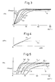
- the required throttle opening degree ⁇ tr is found using the map such as shown in FIG. 3.
- the map of FIG. 3 links the intake pipe internal pressure Pm and the throttle opening degree ⁇ t for realizing the intake pipe internal pressure Pm.
- the relations between the intake pipe internal pressure Pm and the throttle opening degree ⁇ t for the five different engine speeds NEa, NEb, NEc, NEd, and NEe are expressed by the curves Ca, Cb, Cc, Cd, and Ce. Note that here NEa ⁇ NEb ⁇ NEc ⁇ NEd ⁇ NEe.
- the map shown in FIG. 3 is prepared in advance.
- the required throttle opening degree ⁇ tr is found based on this map from the required intake pipe internal pressure Pmr found at step 105. Further, when the required throttle opening degree ⁇ tr is found at step 109, the routine proceeds to step 111, where the required throttle opening degree ⁇ tr is made the target throttle opening degree ⁇ tta as it is.
- the routine proceeds to step 113.
- the throttle opening degree ⁇ twot making the intake pipe internal pressure Pm the pressure Pmwot is found. This throttle opening degree ⁇ twot can also be found from the map such as shown in FIG. 3.
- the throttle opening degree ⁇ twot to be found is a value on the abscissa at the intersection of the curve Cc and the broken line R showing that the intake pipe internal pressure Pm is the pressure Pmwot in FIG. 3.
- the addition corrected throttle opening degree ⁇ tc is found.
- the addition corrected throttle opening degree ⁇ tc can be found using the map shown in for example FIG. 4.
- the example of FIG. 4 shows the case where the engine speed NE is NEc.
- the map shown in FIG. 4 able to be used here can be obtained in the following way. That is, the parts of the curves Ca, Cb, Cc, Cd, and Ce (shown in FIG. 3) showing the relationships between the intake pipe internal pressure Pm and the throttle opening degree ⁇ t for realizing the intake pipe internal pressure Pm where the intake pipe internal pressure Pm is the pressure Pmwot or more are made straight lines such as shown by the dot-chain lines in FIG. 5.
- the lines fa, fb, fc, fd, and fe obtained by this conversion specifically are the lines passing through the intersections of the curves Ca, Cb, Cc, Cd, and Ce with the broken line R showing that the intake pipe internal pressure Pm is the pressure Pmwot and the points on the curves Ca, Cb, Cc, Cd, and Ce where the inclinations become less than predetermined values, in other words, the lines passing through the points on the curves Ca, Cb, Cc, Cd, and Ce where the intake pipe internal pressure Pm becomes the predetermined pressure Pmwot and the point where the ratio (or magnitude) of change of the intake pipe internal pressure Pm with respect to change of the opening degree of the throttle valve becomes the above predetermined value or less.
- the predetermined value for example, the allowable lower limit of the ratio of change of the intake pipe internal pressure Pm with respect to change of the opening degree of the throttle valve is used.
- the lines when moving the starting points of the lines fa, fb, fc, fd, and fe obtained in this way that is, the intersections between the curves Ca, Cb, Cc, Cd, and Ce and the broken line R) to the origin of the coordinates are found.
- These lines are conversion lines for converting the pressure difference ⁇ Pm to the addition corrected throttle opening degree ⁇ tc. Due to this, the map shown in FIG. 4 is formed. That is, for example, FIG. 4 is an example of the case where the engine speed NE is NEc, and the conversion line Fc shown in the map of FIG. 4 is the line when moving the starting point of the line fc of FIG. 3 to the origin of the coordinates.
- the equation of the conversion line used in the map shown in FIG. 4 is found in advance.
- the addition corrected throttle opening degree ⁇ tc is found in accordance with the pressure difference ⁇ Pm based on the equation of the conversion line. Note that this is substantially the same as finding the addition corrected throttle opening degree ⁇ tc in accordance with the pressure difference ⁇ Pm based on this map.
- step 119 if the target throttle opening degree ⁇ tta is determined at step 111 or step 117, at the next step 119, the throttle valve 18 is controlled so that the throttle opening degree ⁇ t becomes the target throttle opening degree ⁇ tta to control the intake air amount. Further, when step 119 ends, the routine returns to step 101, from where the similar control is repeated.
- the required intake pipe internal pressure Pmr becomes the predetermined pressure Pmwot or more and hunting of the throttle opening degree ⁇ t is feared, it is possible to make the ratio of change of the intake pipe internal pressure Pm with respect to changes in the opening degree of the throttle valve envisioned when determining the target throttle opening degree ⁇ tta the allowable lower limit or more.
- the ratio of change of the target throttle opening degree ⁇ tta with respect to a change in the required intake pipe internal pressure Pmr can be made an allowable value or less.
- This embodiment can be realized by the configuration shown in FIG. 1 and has many parts in common with the above embodiment. Explanation of the parts in common will in principle be omitted.
- FIG. 6 is a flow chart showing the control routine for controlling the throttle opening degree performed in this embodiment.
- the control at steps 201, 203, 205, 207, 209, 211, and 213 in this control routine is similar to the control at steps 101, 103, 105, 107, 109, 111, and 113 in the control routine shown in FIG. 2, so the explanation will be omitted here.
- step 213 If the throttle opening degree ⁇ twot making the intake pipe internal pressure Pm the pressure Pmwot is found at step 213, the routine proceeds to step 214 where a reference addition corrected throttle opening degree ⁇ tck in the case where the engine speed NE is a predetermined reference engine speed NEk is found.
- the control here is substantially the same as the control of step 115 in the control routine shown in FIG. 2 except that a reference equation (or reference map) which is a linear equation (or map) corresponding to the reference engine speed NEk is used.
- the routine proceeds to step 215.
- the control at the next step 219 is similar to the control at step 119 in the control routine shown in FIG. 2.
- a control device of an internal combustion engine which determines a target throttle opening degree in accordance with a required intake pipe internal pressure and which suppresses the occurrence of hunting of the throttle opening degree is provided, wherein, when the required intake pipe internal pressure becomes a predetermined pressure or more, the target throttle opening degree is determined by adding an addition-corrected throttle opening degree calculated in accordance with a difference between the required intake pipe internal pressure and the predetermined pressure based on a predetermined equation to an opening degree of a throttle valve making the intake pipe internal pressure the predetermined pressure.
Landscapes
- Engineering & Computer Science (AREA)
- Chemical & Material Sciences (AREA)
- Combustion & Propulsion (AREA)
- Mechanical Engineering (AREA)
- General Engineering & Computer Science (AREA)
- Electrical Control Of Air Or Fuel Supplied To Internal-Combustion Engine (AREA)
- Combined Controls Of Internal Combustion Engines (AREA)
Applications Claiming Priority (1)
| Application Number | Priority Date | Filing Date | Title |
|---|---|---|---|
| JP2004304331A JP4270099B2 (ja) | 2004-10-19 | 2004-10-19 | 内燃機関の制御装置 |
Publications (3)
| Publication Number | Publication Date |
|---|---|
| EP1650417A2 true EP1650417A2 (de) | 2006-04-26 |
| EP1650417A3 EP1650417A3 (de) | 2008-02-20 |
| EP1650417B1 EP1650417B1 (de) | 2009-02-18 |
Family
ID=35667096
Family Applications (1)
| Application Number | Title | Priority Date | Filing Date |
|---|---|---|---|
| EP05022366A Ceased EP1650417B1 (de) | 2004-10-19 | 2005-10-13 | Vorrichtung zur Regelung einer Brennkraftmaschine |
Country Status (4)
| Country | Link |
|---|---|
| US (1) | US7204231B2 (de) |
| EP (1) | EP1650417B1 (de) |
| JP (1) | JP4270099B2 (de) |
| DE (1) | DE602005012770D1 (de) |
Cited By (1)
| Publication number | Priority date | Publication date | Assignee | Title |
|---|---|---|---|---|
| CN101680384B (zh) * | 2007-05-14 | 2012-07-18 | 丰田自动车株式会社 | 内燃机的控制装置 |
Families Citing this family (5)
| Publication number | Priority date | Publication date | Assignee | Title |
|---|---|---|---|---|
| JP5393506B2 (ja) * | 2010-01-27 | 2014-01-22 | 三菱重工業株式会社 | エンジンの吸気系に用いられる制御弁の制御装置及び制御方法 |
| IT201800009528A1 (it) * | 2018-10-17 | 2020-04-17 | Fpt Ind Spa | Dispositivo di controllo di una valvola a farfalla di un motore a combustione interna e motore a combustione interna comprendente detto dispositivo |
| JP7135719B2 (ja) * | 2018-10-24 | 2022-09-13 | トヨタ自動車株式会社 | スロットル制御装置 |
| JP7380347B2 (ja) * | 2020-03-10 | 2023-11-15 | トヨタ自動車株式会社 | スロットル制御装置 |
| JP7380368B2 (ja) * | 2020-03-24 | 2023-11-15 | トヨタ自動車株式会社 | スロットル制御装置 |
Citations (1)
| Publication number | Priority date | Publication date | Assignee | Title |
|---|---|---|---|---|
| JPH0565845A (ja) | 1991-03-06 | 1993-03-19 | Hitachi Ltd | エンジン制御方法及びシステム |
Family Cites Families (7)
| Publication number | Priority date | Publication date | Assignee | Title |
|---|---|---|---|---|
| US4799467A (en) * | 1986-07-16 | 1989-01-24 | Honda Giken Kogyo Kabushiki Kaisha | Throttle valve control system for an internal combustion engine |
| US4791902A (en) * | 1986-07-16 | 1988-12-20 | Honda Giken Kogyo Kabushiki Kaisha | Throttle valve control system for an internal combustion engine |
| JPH08144820A (ja) * | 1994-11-22 | 1996-06-04 | Honda Motor Co Ltd | 内燃エンジンのスロットル弁制御装置 |
| AUPO271796A0 (en) * | 1996-10-02 | 1996-10-24 | Orix Vehicle Technology Pty Ltd | Improved engine control unit |
| JP4075233B2 (ja) | 1999-07-29 | 2008-04-16 | トヨタ自動車株式会社 | 内燃機関の吸入空気量予測装置 |
| JP4140242B2 (ja) * | 2002-01-28 | 2008-08-27 | トヨタ自動車株式会社 | 内燃機関の制御装置 |
| JP4207718B2 (ja) * | 2003-08-26 | 2009-01-14 | トヨタ自動車株式会社 | 内燃機関の制御装置 |
-
2004
- 2004-10-19 JP JP2004304331A patent/JP4270099B2/ja not_active Expired - Fee Related
-
2005
- 2005-10-12 US US11/247,261 patent/US7204231B2/en not_active Expired - Lifetime
- 2005-10-13 EP EP05022366A patent/EP1650417B1/de not_active Ceased
- 2005-10-13 DE DE602005012770T patent/DE602005012770D1/de not_active Expired - Lifetime
Patent Citations (1)
| Publication number | Priority date | Publication date | Assignee | Title |
|---|---|---|---|---|
| JPH0565845A (ja) | 1991-03-06 | 1993-03-19 | Hitachi Ltd | エンジン制御方法及びシステム |
Cited By (1)
| Publication number | Priority date | Publication date | Assignee | Title |
|---|---|---|---|---|
| CN101680384B (zh) * | 2007-05-14 | 2012-07-18 | 丰田自动车株式会社 | 内燃机的控制装置 |
Also Published As
| Publication number | Publication date |
|---|---|
| JP2006118373A (ja) | 2006-05-11 |
| JP4270099B2 (ja) | 2009-05-27 |
| DE602005012770D1 (de) | 2009-04-02 |
| EP1650417B1 (de) | 2009-02-18 |
| US7204231B2 (en) | 2007-04-17 |
| EP1650417A3 (de) | 2008-02-20 |
| US20060081216A1 (en) | 2006-04-20 |
Similar Documents
| Publication | Publication Date | Title |
|---|---|---|
| EP1437498B1 (de) | Viertaktmotorsteuervorrichtung und -steuerverfahren | |
| US8606489B2 (en) | Ignition timing control system for internal combustion engine | |
| US7373922B2 (en) | Intake air amount control apparatus and intake air amount control method of internal combustion engine | |
| EP1447550B1 (de) | Motorsteuervorrichtung | |
| US8620563B2 (en) | Fuel supply apparatus for internal combustion engine | |
| JP5197528B2 (ja) | エンジン負荷検知装置およびエンジン負荷検知方法 | |
| EP1650417B1 (de) | Vorrichtung zur Regelung einer Brennkraftmaschine | |
| EP1249593B1 (de) | Steuerungssystem und Methode für eine Mehrzylinder-Brennkraftmaschine | |
| EP1452715B1 (de) | Motorsteuerung | |
| US6983646B2 (en) | Atmospheric pressure detection device of four-stroke engine and method of detecting atmospheric pressure | |
| US7181336B2 (en) | Control system of internal combustion engine | |
| EP1602811B1 (de) | Regler für eine Brennkraftmaschine | |
| EP1837510B1 (de) | Steuerung von verbrennungsmotoren | |
| CN101037967A (zh) | 发动机燃油效率确定 | |
| JP2004346869A (ja) | 内燃機関の制御装置 | |
| EP1431551B1 (de) | Steuerung für brennkraftmaschine | |
| US20060136118A1 (en) | Method and device for determining the phase position of a camshaft of an internal combustion engine | |
| JP4871307B2 (ja) | エンジンの燃料制御装置 | |
| EP1627141A1 (de) | Steuervorrichtung für eine mehrzylindrige brennkraftmaschine | |
| JP2003056378A (ja) | クランクシャフト回転センサ | |
| JP2008025404A (ja) | 筒内圧センサの校正装置 | |
| JP2005163715A (ja) | 内燃機関の燃料噴射制御装置 | |
| JP2003148182A (ja) | 内燃機関の制御装置 | |
| JP2009167949A (ja) | 内燃機関の燃焼エネルギー算出装置及び内燃機関 | |
| JP2007278133A (ja) | エンジン軸トルク推定装置 |
Legal Events
| Date | Code | Title | Description |
|---|---|---|---|
| PUAI | Public reference made under article 153(3) epc to a published international application that has entered the european phase |
Free format text: ORIGINAL CODE: 0009012 |
|
| 17P | Request for examination filed |
Effective date: 20051013 |
|
| AK | Designated contracting states |
Kind code of ref document: A2 Designated state(s): AT BE BG CH CY CZ DE DK EE ES FI FR GB GR HU IE IS IT LI LT LU LV MC NL PL PT RO SE SI SK TR |
|
| AX | Request for extension of the european patent |
Extension state: AL BA HR MK YU |
|
| PUAL | Search report despatched |
Free format text: ORIGINAL CODE: 0009013 |
|
| AK | Designated contracting states |
Kind code of ref document: A3 Designated state(s): AT BE BG CH CY CZ DE DK EE ES FI FR GB GR HU IE IS IT LI LT LU LV MC NL PL PT RO SE SI SK TR |
|
| AX | Request for extension of the european patent |
Extension state: AL BA HR MK YU |
|
| RIC1 | Information provided on ipc code assigned before grant |
Ipc: F02D 41/14 20060101ALI20080116BHEP Ipc: F02D 35/00 20060101ALI20080116BHEP Ipc: F02D 41/00 20060101ALI20080116BHEP Ipc: F02D 11/10 20060101AFI20060202BHEP Ipc: F02D 9/02 20060101ALI20080116BHEP |
|
| GRAP | Despatch of communication of intention to grant a patent |
Free format text: ORIGINAL CODE: EPIDOSNIGR1 |
|
| GRAS | Grant fee paid |
Free format text: ORIGINAL CODE: EPIDOSNIGR3 |
|
| AKX | Designation fees paid |
Designated state(s): DE FR |
|
| GRAA | (expected) grant |
Free format text: ORIGINAL CODE: 0009210 |
|
| AK | Designated contracting states |
Kind code of ref document: B1 Designated state(s): DE FR |
|
| REF | Corresponds to: |
Ref document number: 602005012770 Country of ref document: DE Date of ref document: 20090402 Kind code of ref document: P |
|
| PLBE | No opposition filed within time limit |
Free format text: ORIGINAL CODE: 0009261 |
|
| STAA | Information on the status of an ep patent application or granted ep patent |
Free format text: STATUS: NO OPPOSITION FILED WITHIN TIME LIMIT |
|
| 26N | No opposition filed |
Effective date: 20091119 |
|
| REG | Reference to a national code |
Ref country code: DE Ref legal event code: R084 Ref document number: 602005012770 Country of ref document: DE Effective date: 20130717 |
|
| REG | Reference to a national code |
Ref country code: FR Ref legal event code: PLFP Year of fee payment: 12 |
|
| REG | Reference to a national code |
Ref country code: FR Ref legal event code: PLFP Year of fee payment: 13 |
|
| REG | Reference to a national code |
Ref country code: FR Ref legal event code: PLFP Year of fee payment: 14 |
|
| PGFP | Annual fee paid to national office [announced via postgrant information from national office to epo] |
Ref country code: FR Payment date: 20180913 Year of fee payment: 14 |
|
| PGFP | Annual fee paid to national office [announced via postgrant information from national office to epo] |
Ref country code: DE Payment date: 20181002 Year of fee payment: 14 |
|
| REG | Reference to a national code |
Ref country code: DE Ref legal event code: R119 Ref document number: 602005012770 Country of ref document: DE |
|
| PG25 | Lapsed in a contracting state [announced via postgrant information from national office to epo] |
Ref country code: DE Free format text: LAPSE BECAUSE OF NON-PAYMENT OF DUE FEES Effective date: 20200501 |
|
| PG25 | Lapsed in a contracting state [announced via postgrant information from national office to epo] |
Ref country code: FR Free format text: LAPSE BECAUSE OF NON-PAYMENT OF DUE FEES Effective date: 20191031 |