EP1650498B1 - Sicherheitsabschaltung für Dampferzeugungsvorrichtungen unter Druck - Google Patents
Sicherheitsabschaltung für Dampferzeugungsvorrichtungen unter Druck Download PDFInfo
- Publication number
- EP1650498B1 EP1650498B1 EP05256603.1A EP05256603A EP1650498B1 EP 1650498 B1 EP1650498 B1 EP 1650498B1 EP 05256603 A EP05256603 A EP 05256603A EP 1650498 B1 EP1650498 B1 EP 1650498B1
- Authority
- EP
- European Patent Office
- Prior art keywords
- valve
- lever
- cam
- water
- safety cut
- Prior art date
- Legal status (The legal status is an assumption and is not a legal conclusion. Google has not performed a legal analysis and makes no representation as to the accuracy of the status listed.)
- Expired - Lifetime
Links
Images



Classifications
-
- F—MECHANICAL ENGINEERING; LIGHTING; HEATING; WEAPONS; BLASTING
- F22—STEAM GENERATION
- F22B—METHODS OF STEAM GENERATION; STEAM BOILERS
- F22B1/00—Methods of steam generation characterised by form of heating method
- F22B1/28—Methods of steam generation characterised by form of heating method in boilers heated electrically
- F22B1/284—Methods of steam generation characterised by form of heating method in boilers heated electrically with water in reservoirs
Definitions
- the present invention relates to a safety cut-off for any type of device, preferably for domestic use, which is designed to produce pressurised vapour for different purposes.
- the present invention relates to a safety cut-off for any type of device which is designed to produce pressurised steam for different purposes, such as to avoid the risk of accidents by scalding when filling with water, and when pressurised steam exists in the steam chamber.
- EP0662298 refers to a safety water reservoir seal for coffee makers having a valve working with a first spring which biases an open seal position and the a second spring biasing a closed seal position and associated to a lever drivable against its spring.
- the lever is driven by a cam associated a cover. When the cover is swivelled sideways the lever is made to swivel, thereby freeing the one-way valve seal.
- GB2048426 discloses a locking device for pressure-cooker lids for preventing the opening when there is internal pressure. It has a lid with a supporting crossbar the ends of which rest on the edge of the container opening, and a lever pivoted to the lid and capable of moving between an opening position and a closing position. In the closing position a cam-shaped portion of the lever acts against the crossbar causing the peripheral edge of the lid to press against a sealing.
- the lever has an apertured portion designed for engaging a locking pin operated by internal pressure, the pin being provided in the lid for engaging the portion when the lever is in its lowered position.
- the present invention proposes a safety cut-off for pressurised water vapour producing devices for domestic use, which complies with a particular composition consisting of a folding top which is disposed in closing/opening relationship with the access to a funnel through which the water must be poured for filling and refilling of the boiler in which the steam is produced, which top has a top shaft in relation with which there rotates a cam which is integral with the top, and which has an active periphery which is applied to a camshaft which is incorporated in a lever which can rotate relative to a lever shaft, and which, spaced from the latter, has an aperture through which there slides vertically a rod, which at its lower end incorporates a filling valve which is interposed between the funnel and a chamber for output of the steam produced in the boiler, which filling valve can adopt two, upper and lower operative positions such that, in the upper position, the filling valve acts as a shutter seat on the lower plane of a valve passage which puts the funnel into communication with the output chamber, and, in the
- This arrangement ensures that, when the top is raised and pressurised steam exists in the steam chamber, the valve for filling and closure will remain closed, thus preventing steam from escaping and scalding the user.
- This closure arrangement provides functionality which ensures prevention of the above-described risk of accidents.
- the combined configuration of a folding top cam and lever camshaft means that, when the top is open, the lower position of the lever is forced against the spring which impels its upper position, such that the action of the helical spring, which impels the lower position of the water filling valve, together with the weight of the filling valve itself, means that the filling valve effectively occupies this lower position which permits passage of water to the boiler through the valve passage.
- the position in which the folding top is closed gives rise to relaxing of the spring, which, when it recovers resiliently, leads to raising of the rod, and thus of the filling valve, by means of the action of the aperture in the lever on the flange of the rod, which takes place by means of compression of the helical spring, and provides the position of closure of the water filling valve.
- the filling valve is closed, the pressure of the water vapour generated in the boiler maintains this situation of closure even if someone opens the top to carry out refilling, without realising that there is pressurised water vapour in the device. This means that the top can be opened in any circumstance without any danger of the pressurised water being able to be projected towards the user, who remains protected against the risk of accidental scalding.
- the lower position of the lever is compatible with the upper position (of closure) of the valve for filling with water and closure, since the rod of the latter passes freely through its aperture, and it is only when the rod and lever are in their lower positions that the raising of the lever also draws the rod such that its flange cannot pass through the aperture in the lever, as previously described.
- Another advantageous feature of the invention consists in the ease and convenience of access which, for the filling with water, presupposes the action of opening/closure of a folding top, compared with the unscrewing and subsequent re-screwing of a stopper which requires many turns in order to provide safe and efficient closure.
- another feature of the invention is that on its free edge the top has a thumb grip which facilitates its handling.
- Another feature of the invention is that, in parallel with the filling valve, there exists a safety valve which is interposed between the funnel and the output chamber.
- the rod at its upper end, is extended by means of an extension which at its tip incorporates an ostentatious colour, and is guided in a hole which communicates with the funnel as closed by the top, and, with reference to the position of opening, or the lower position, and the position of closure, or the upper position, of the valve for filling with water and closure, the extension occupies respective lower and upper positions, such that, in the lower position, its coloured tip is retracted in the hole, whereas, in the upper position, the tip penetrates in a cavity which is formed in a transparent cover located in the funnel.
- the safety cut-off includes a plate interposed between the valve passage and the lever, the size of the periphery of which is designed to leave a channel of communication with the funnel, which, although narrow, allows water to access the steam chamber.
- This solution is specifically designed to prevent steam produced spontaneously when filling the device with cold water, as a result of the steam chamber still being hot from recent previous use, from being able to escape to the exterior and be projected onto the user, and provides that the generated steam will startle the user but not injure him, unlike the previous situation, which is now avoided.
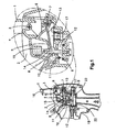
- Figure 1 shows in cross-section a device for producing pressurised water vapour for domestic use, which is provided with a folding top, in accordance with a first embodiment of the present invention.
- This Figure incorporates an enlarged detail of the device, in the position in which the top is open.
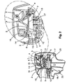
- Figure 2 is the same view as Figure 1 , but relates to the closed position of the top.
- Figure 3 is the same view as Figure 2 , but with the top open when there is water vapour pressure in the boiler.
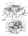
- Figure 4 is a similar view to that of Figure 1 , and represents the situation of functioning in the case of a pressurised water vapour spray gun, illustrating the action of firing, as can be seen clearly in the enlarged detail incorporated in this Figure.
- Figure 5 shows in cross-section a device for producing pressurised water vapour for domestic use, which is provided with a folding top, in accordance with a second embodiment of the present invention.
- Figure 6 is the same view as Figure 5 , but relates to the position in which the top is closed and pressure exists in the steam chamber.
- Figure 7 is the same view as Figure 5 , but relates to the position in which the top is open and pressure exists in the steam chamber.
- the purpose of the invention is to avoid scalding and other possible damage which can be caused by the devices known hitherto in this field, when the user inadvertently proceeds to fill the boiler with water, without realising that the device is functioning and contains pressurised water vapour in its interior.
- the existing arrangement which provides for closure by means of a threaded stopper, does not provide for safety of the user, since, when the stopper is loosened, pressurised water vapour begins to rise towards the user, or the stopper can even rise and be launched as if it were a projectile.
- Figures 1 to 4 illustrate a device in accordance with a first embodiment of the present invention.
- the safety cut-off comprises a folding top 1 which is disposed in closing/opening relationship at the access to a funnel 2, through which water is poured for filling and refilling of the boiler in which the steam is produced.
- the top 1 has a top shaft 3, in relation to which there rotates a cam 4 which is integral with the top 1 and which has an active periphery which is applied to a cam surface 6 which is incorporated in a lever 5, which can rotate relative to a lever shaft 7, and which, spaced from the latter, has an aperture 8 through which there slides vertically a rod 10, which at its lower end incorporates a valve 9 for filling and closure, which is Interposed between the funnel 2 and a chamber 12 for the steam produced in the boiler.
- the valve 9 for filling and closure can adopt one of two, upper and lower, operative positions, such that, in the upper position, the valve 9 for filling and closure acts as a shutter seat on the lower plane of a valve passage 11 which puts the funnel 2 out of communication with the steam chamber 12, and, in the lower position, the valve 9 for filling and closure is separated from the seat.
- the lever 5 has a torsion spring 13 associated therewith, such that the lever 5 can oscillate between two, upper and lower, operative positions, such that, in the lower position, the torsion spring 13 is in its state of greatest relative tension, and the contact between the cam surface 6 of the lever 5 and the cam 4 of the top 1 takes place on a part of the cam 4 with a larger radius than that which is provided by the open position of the top 1, and, in the upper position, the torsion spring 13 is in its state of greatest relative relaxation, and the contact between the cam surface 6 and cam 4 takes place on a part of the cam 4 with a smaller radius than that which is provided by the closed position of the top 1.
- the rod 10 passes through the aperture 8 in the lever 5, and projects from an end part on which there exists a flange 14 which has a size larger than the diameter of the aperture 8, and on which there is supported the lower end of a helical compression spring 15, which is weaker than the torsion spring 13 which is associated with the lever 5, and which impels the filling and closure valve 9 to a lower position, in which the flange 14 remains against the aperture 8 and the lever 5 occupies its lower position.
- FIGs 1 to 3 illustrate the functionality of the device.
- the folding top 1 is open, and there is no steam pressure in the boiler.
- the lever 5 occupies its lower position against the resilient action of the torsion spring 13, which in turn means that, by means of the action of the helical spring 15 and its own weight, the valve 9 occupies its lower position which is delimited by the abutment of the flange 14 of the rod 10 against the aperture 8 of the lever 5, which leaves the valve passage 11 free for filling the boiler with water.
- FIG. 2 illustrates the folding top 1
- this conjugated configuration of the cam 4 and cam surface 6 removes the pressure on the torsion spring 13, and its resilient recovery gives rise to transfer of the lever 5 to its upper position, drawing with it the rod 10 because of the action of the aperture 8 on the flange 14 of the latter.
- Figure 3 illustrates the safety function wherein the folding top 1 can be opened without danger, since the pressure of the water vapour ensures the closure of the valve 9, providing a greatly reduced vapour pressure, which in all cases is insufficient to cause any damage to the user.
- Another feature of the present invention is a safety valve 17 which, in parallel to the valve 9, is interposed between the funnel 2 and the vapour chamber 12.
- Figure 4 illustrates the actuation in spraying of the pressurised water vapour as generated, where the device for this purpose is of the gun type.
- the trigger 18 when the trigger 18 is pressed, the trigger 18 acts on a thruster 19 which acts on the steam output valve shaft 20, separating the latter from its closure seat 21, and thus enabling the release of the pressurised water vapour.
- FIGS 5 to 7 illustrate a device in accordance with a second embodiment of the present invention.
- the rod 10 is extended by means of an extension 10.1, which at its tip has an ostentatious colour, and is guided in a hole 24 which communicates with the funnel 2 as closed by the top 1.
- the extension 10.1 occupies respective lower and upper positions, such that, in the lower position, the coloured tip is retracted In the hole 24, whereas, in the upper position, the coloured tip penetrates in a cavity 25.1 which is formed in a transparent cover 25 located in the funnel 2.
- Figures 5 to 7 illustrate the different functioning situations.
- Figure 5 shows the state in which the steam chamber 12 is without steam and cold, where the device is ready to be filled with water in order to begin operation. It can be seen that the extension 10.1 of the rod 10 is retracted in the hole 24 and its coloured tip cannot be seen through the transparent cover 25 which acts as a viewer.
- the top 1 is closed, and when the equipment is connected up to the mains supply, the steam pressure begins to be sufficient, as illustrated in Figure 6 , and the extension 10.1 of the rod 10 slides through the hole 24, such that the coloured tip penetrates into the cavity 25.1 in the viewer as constituted by the transparent cover 25.
- valve passage 11 there is interposed a plate 26, the size of the periphery of which is designed to leave a channel of communication with the funnel 2, which, although narrow, allows water to access the steam chamber 12.
- this device makes it possible to prevent the steam from being projected dangerously towards the user when the steam chamber 12 is filled with cold water when it is open and empty, but still hot from recent use.
Landscapes
- Engineering & Computer Science (AREA)
- Life Sciences & Earth Sciences (AREA)
- Sustainable Development (AREA)
- Sustainable Energy (AREA)
- Physics & Mathematics (AREA)
- Thermal Sciences (AREA)
- Mechanical Engineering (AREA)
- General Engineering & Computer Science (AREA)
- Mechanically-Actuated Valves (AREA)
- Cookers (AREA)
- Safety Valves (AREA)
Claims (6)
- Sicherheitsabschaltung für Vorrichtungen, die Druckwasserdampf erzeugen, vorzugsweise für den häuslichen Gebrauch, gekennzeichnet dadurch, dass sie einen Klappdeckel (1) umfasst, der in Öffnungs- und Schlussverhältnis mit einem Zugang zu einer Aussparung (2), vorzugsweise einem Trichter, angeordnet ist, durch den Wasser eingegossen wird, um einen Dampfkessel zu füllen und nachzufüllen, in dem Wasserdampf erzeugt wird, wobei der Klappdeckel (1) eine Welle (3) hat, um welche eine Kurvenscheibe (4) herumdreht, die in dem Klappdeckel (1) integriert ist, und welche eine aktive Oberfläche hat, die auf eine Kurve (6) eines Hebels (5) aufgetragen wird, der bezüglich einer Hebelwelle (7) drehbar ist, und die, beabstandet von dem Letzteren einen Durchlass (8) hat, durch welche eine Stange (10) geschoben wird, die an einem Ende ein Ventil (9) zur Füllung und Abschließung umfasst, das zwischen der Aussparung (2) und einer Kammer (12) eingeschoben ist, die dazu dient, den im Dampfkessel erzeugten Wasserdampf zu enthalten, wobei das Ventil (9) eine von zwei funktionsfähigen Positionen annehmen kann, sodass, in einer Position, das Ventil (9) einen Ventildurchgang (11) schließt, der eine Verbindung zwischen der Aussparung (2) und der Kammer (12) bereitstellt und, in der anderen Position, das Ventil (9) geöffnet ist.
- Sicherheitsabschaltung nach Anspruch 1, wobei der Hebel (5) ein erstes Vorspannungselement (13), vorzugsweise eine Drehfeder, hat, das damit verbunden ist und beweglich zwischen zwei funktionsfähigen Positionen ist sodass, in einer Position, das erste Vorspannungselement (13) sich in einem Zustand höher relativer Spannung befindet und der Kontakt zwischen der Kurve (6) und der Kurvenscheibe (4) auf einem Teil der Kurvenscheibe (4) erfolgt, der ein höheres Radius hat und, in der anderen Position, das Vorspannungselement (13) sich in einem Zustand höher relativer Entspannung befindet und der Kontakt zwischen der Kurve (6) und der Kurvenscheibe (4) auf einem Teil der Kurvenscheibe (4) erfolgt, der ein kleineres Radius hat und, im Ventildurchgang (11), die Stange (10) durch den Durchlass (8) des Hebels (5) hindurchgeht und aus einem Ende herausragt, das einen Flansch (14) umfasst, der größer als der Durchgang (8) ist und auf dem ein Ende eines zweiten Vorspannungselements (15), vorzugsweise einer Druckfeder, abgestützt ist, das schwächer als das erste Vorspannungselement (13) ist und das Ventil (9) bis zu einer geöffneten Position vorspannt, in welcher der Flansch (14) angrenzend an den Durchgang (8) bleibt und der Hebel (5) die geöffnete Position besitzt.
- Sicherheitsabschaltung nach einem der vorhergehenden Ansprüche, weiterhin umfassend eine Wasserrückhaltedichtung (22), die eine Verschüttung von Wasser aus dem Dampfkessel verhindert, wenn die Vorrichtung horizontal angeordnet ist, sodass nur Wasserdampf ausströmt und die Rückhaltedichtung (22) wiederum ein Dichtungselement zwischen dem Dampfkessel und einem Halter (23) der Sicherheitsabschaltung bildet.
- Sicherheitsabschaltung nach einem der vorhergehenden Ansprüche, wobei, an einem Ende, die Stange (10) durch eine Verlängerung (10.1) ausgestreckt ist, die an ihrer Spitze gefärbt ist, vorzugsweise in einer auffälligen Farbe, und in eine Öffnung (24) eingeführt wird, die mit der mittels des Klappdeckels (1) geschlossenen Aussparung (2) verbunden ist und, bezüglich der geöffneten und geschlossenen Positionen des Ventils (9), die Verlängerung (10.1) eine entsprechende Position aus eingezogenen oder ausgestreckten Positionen besitzt sodass, die gefärbte Spitze in der eingezogenen Position in die Öffnung (24) eingezogen wird und, in der ausgestreckten Position, die gefärbte Spitze bis in eine Höhlung (25.1) ausgestreckt wird, die in einer sich in der Aussparung (2) befindenden durchsichtigen Decke (25) gebildet ist.
- Sicherheitsabschaltung nach einem der vorhergehenden Ansprüche, weiterhin umfassend eine Platte (26) zwischen dem Ventildurchgang (11) und dem Hebel (5), deren Umfang eine Größe hat, die so ausgebildet ist, um einen Verbindungskanal mit der Aussparung (2) zu bilden, der, wenn auch eng, den Durchgang von Wasser in die Kammer (12) ermöglicht und ein gefährliches Ausströmen von Wasserdampf auf den Benutzer verhindert, wenn die Kammer (12) mit kaltem Wasser gefüllt wird, wenn sie geöffnet und leer ist, aber immer noch heiß aufgrund der letzten Betätigung ist.
- Schusswaffenähnliche Vorrichtung umfassend eine Sicherheitsabschaltung nach einem der vorhergehenden Ansprüche.
Applications Claiming Priority (2)
| Application Number | Priority Date | Filing Date | Title |
|---|---|---|---|
| ES200402527A ES2289845B1 (es) | 2004-10-22 | 2004-10-22 | Cierre de seguridad para aparatos de produccion de vapor de agua a presion para uso domestico. |
| ES200502432A ES2302582B1 (es) | 2004-10-22 | 2005-10-06 | Mejoras en la patente de invencion p-200402527 por "cierre de seguridad para aparatos de produccion de vapor de agua a presion para uso domestico". |
Publications (2)
| Publication Number | Publication Date |
|---|---|
| EP1650498A1 EP1650498A1 (de) | 2006-04-26 |
| EP1650498B1 true EP1650498B1 (de) | 2013-07-17 |
Family
ID=35529818
Family Applications (1)
| Application Number | Title | Priority Date | Filing Date |
|---|---|---|---|
| EP05256603.1A Expired - Lifetime EP1650498B1 (de) | 2004-10-22 | 2005-10-21 | Sicherheitsabschaltung für Dampferzeugungsvorrichtungen unter Druck |
Country Status (5)
| Country | Link |
|---|---|
| US (1) | US7207358B2 (de) |
| EP (1) | EP1650498B1 (de) |
| JP (1) | JP2006145030A (de) |
| BR (1) | BRPI0504443A (de) |
| CA (1) | CA2524032A1 (de) |
Families Citing this family (5)
| Publication number | Priority date | Publication date | Assignee | Title |
|---|---|---|---|---|
| RU2387903C1 (ru) * | 2009-03-17 | 2010-04-27 | Федеральное Государственное Унитарное Предприятие "Научно-Производственное Объединение "Техномаш" | Предохранительное запорное устройство |
| ES2455224T3 (es) * | 2010-04-15 | 2014-04-15 | Alfred Kärcher Gmbh & Co. Kg | Equipo de limpieza a vapor |
| US20210330118A1 (en) * | 2015-02-04 | 2021-10-28 | Hamilton Beach Brands, Inc. | Beverage Maker |
| US9585513B2 (en) * | 2015-02-04 | 2017-03-07 | Hamilton Beach Brands, Inc. | Pump operated beverage maker |
| US9980602B2 (en) * | 2015-02-04 | 2018-05-29 | Hamilton Beach Brands, Inc. | Beverage maker |
Family Cites Families (12)
| Publication number | Priority date | Publication date | Assignee | Title |
|---|---|---|---|---|
| US3865277A (en) * | 1972-12-05 | 1975-02-11 | Bras Spa | Beverage-dispensing machine |
| US4078722A (en) * | 1976-10-28 | 1978-03-14 | A. W. Cash Valve Manufacturing Corporation | Relief valve |
| GB2048426B (en) * | 1979-03-22 | 1983-05-25 | Bertola A | Automatic locking device for the lid-opening lever of a pressure-cooker |
| FR2460644A1 (fr) * | 1979-07-10 | 1981-01-30 | Seb Sa | Pulverisateur de vapeur d'eau, a usage domestique, pour les soins de la peau |
| JPS57128923A (en) * | 1981-02-02 | 1982-08-10 | Toshiba Mach Co Ltd | Coating equipment of wafer fixing adhesive |
| JPS57128924A (en) * | 1981-02-04 | 1982-08-10 | Hitachi Ltd | Mask positioning and equipment for the same |
| IT1167153B (it) * | 1983-01-14 | 1987-05-13 | Alfredo Cavalli | Sistema valvolare di sicurezza particolarmente per caldaiette di produzione vapore da utilizzare a livello domestico |
| JPS63169032A (ja) * | 1987-01-05 | 1988-07-13 | Nec Corp | 半導体装置 |
| DE4130446A1 (de) * | 1991-09-13 | 1993-03-25 | Braun Ag | Bruehgetraenkemaschine |
| ES1026736Y (es) * | 1994-01-07 | 1994-12-01 | Agrupada Invest Off | Cierre de seguridad para el deposito de agua en cafeteras domesticas a presion de vapor. |
| US5915071A (en) * | 1997-02-18 | 1999-06-22 | National Sanitizer Inc. | Steam cleaning apparatus |
| CN2730266Y (zh) * | 2004-06-25 | 2005-10-05 | 快达实业有限公司 | 电热开水保温水壶 |
-
2005
- 2005-10-20 JP JP2005306283A patent/JP2006145030A/ja active Pending
- 2005-10-21 BR BRPI0504443-0A patent/BRPI0504443A/pt not_active IP Right Cessation
- 2005-10-21 EP EP05256603.1A patent/EP1650498B1/de not_active Expired - Lifetime
- 2005-10-21 CA CA002524032A patent/CA2524032A1/en not_active Abandoned
- 2005-10-21 US US11/255,681 patent/US7207358B2/en not_active Expired - Fee Related
Also Published As
| Publication number | Publication date |
|---|---|
| JP2006145030A (ja) | 2006-06-08 |
| CA2524032A1 (en) | 2006-04-22 |
| EP1650498A1 (de) | 2006-04-26 |
| US20060175435A1 (en) | 2006-08-10 |
| BRPI0504443A (pt) | 2006-06-27 |
| US7207358B2 (en) | 2007-04-24 |
Similar Documents
| Publication | Publication Date | Title |
|---|---|---|
| US6170706B1 (en) | Hand holdable pump spray system | |
| US7641079B2 (en) | Aerosol can valve and cover assembly | |
| US10987526B2 (en) | Descender | |
| US3797748A (en) | Liquid spraying device | |
| US9392892B2 (en) | Lid assembly and drinking container comprising the same | |
| US2506449A (en) | Pressure valve | |
| EP1650498B1 (de) | Sicherheitsabschaltung für Dampferzeugungsvorrichtungen unter Druck | |
| EP0916298A1 (de) | Sicherheitsvorrichtung zur Öffnung oder Schliessung eines Druckkochtopf | |
| US5215119A (en) | Safety closure for steam pressure coffee machine water reservoirs | |
| CN1763404B (zh) | 用于家用加压水蒸汽产生装置的安全开关 | |
| US1915739A (en) | Automatic spigot or faucet | |
| GB2411219A (en) | Tap with safety lock | |
| US1742676A (en) | Oil can | |
| HK1086873B (en) | A safety cut-off for pressurised water vapour production devices for domestic use | |
| CN201061462Y (zh) | 一种电压力煮器的开盖安全装置 | |
| US1725056A (en) | carlberg | |
| US2701955A (en) | Pocket cigarette lighter | |
| JP6640447B2 (ja) | 供出デバイスおよびそうしたデバイスを備えたパッケージング | |
| US1212086A (en) | Oiler. | |
| KR100516543B1 (ko) | 소화기 | |
| ITMI972497A1 (it) | Coperchio per pentola a pressione con dispositivo di sicurezza | |
| JPS6010596Y2 (ja) | 消火設備用容器弁のレバ−式開放装置 | |
| KR200472161Y1 (ko) | 풀림방지 기능을 갖는 보호캡이 구비된 화장용 용기 | |
| KR920002041Y1 (ko) | 화장품 용기의 펌핑부재 | |
| EP0433146A1 (de) | Wassereinspritzvorrichtung für Dampfbügeleisen mit solch einer Vorrichtung |
Legal Events
| Date | Code | Title | Description |
|---|---|---|---|
| PUAI | Public reference made under article 153(3) epc to a published international application that has entered the european phase |
Free format text: ORIGINAL CODE: 0009012 |
|
| AK | Designated contracting states |
Kind code of ref document: A1 Designated state(s): AT BE BG CH CY CZ DE DK EE ES FI FR GB GR HU IE IS IT LI LT LU LV MC NL PL PT RO SE SI SK TR |
|
| AX | Request for extension of the european patent |
Extension state: AL BA HR MK YU |
|
| 17P | Request for examination filed |
Effective date: 20061023 |
|
| 17Q | First examination report despatched |
Effective date: 20061127 |
|
| AKX | Designation fees paid |
Designated state(s): AT BE BG CH CY CZ DE DK EE ES FI FR GB GR HU IE IS IT LI LT LU LV MC NL PL PT RO SE SI SK TR |
|
| GRAP | Despatch of communication of intention to grant a patent |
Free format text: ORIGINAL CODE: EPIDOSNIGR1 |
|
| GRAP | Despatch of communication of intention to grant a patent |
Free format text: ORIGINAL CODE: EPIDOSNIGR1 |
|
| GRAS | Grant fee paid |
Free format text: ORIGINAL CODE: EPIDOSNIGR3 |
|
| INTG | Intention to grant announced |
Effective date: 20130517 |
|
| GRAA | (expected) grant |
Free format text: ORIGINAL CODE: 0009210 |
|
| AK | Designated contracting states |
Kind code of ref document: B1 Designated state(s): AT BE BG CH CY CZ DE DK EE ES FI FR GB GR HU IE IS IT LI LT LU LV MC NL PL PT RO SE SI SK TR |
|
| REG | Reference to a national code |
Ref country code: GB Ref legal event code: FG4D |
|
| REG | Reference to a national code |
Ref country code: CH Ref legal event code: EP |
|
| REG | Reference to a national code |
Ref country code: IE Ref legal event code: FG4D |
|
| REG | Reference to a national code |
Ref country code: AT Ref legal event code: REF Ref document number: 622447 Country of ref document: AT Kind code of ref document: T Effective date: 20130815 |
|
| REG | Reference to a national code |
Ref country code: DE Ref legal event code: R096 Ref document number: 602005040409 Country of ref document: DE Effective date: 20130912 |
|
| REG | Reference to a national code |
Ref country code: AT Ref legal event code: MK05 Ref document number: 622447 Country of ref document: AT Kind code of ref document: T Effective date: 20130717 |
|
| REG | Reference to a national code |
Ref country code: NL Ref legal event code: VDEP Effective date: 20130717 |
|
| REG | Reference to a national code |
Ref country code: LT Ref legal event code: MG4D |
|
| PG25 | Lapsed in a contracting state [announced via postgrant information from national office to epo] |
Ref country code: CY Free format text: LAPSE BECAUSE OF FAILURE TO SUBMIT A TRANSLATION OF THE DESCRIPTION OR TO PAY THE FEE WITHIN THE PRESCRIBED TIME-LIMIT Effective date: 20130710 Ref country code: IS Free format text: LAPSE BECAUSE OF FAILURE TO SUBMIT A TRANSLATION OF THE DESCRIPTION OR TO PAY THE FEE WITHIN THE PRESCRIBED TIME-LIMIT Effective date: 20131117 Ref country code: LT Free format text: LAPSE BECAUSE OF FAILURE TO SUBMIT A TRANSLATION OF THE DESCRIPTION OR TO PAY THE FEE WITHIN THE PRESCRIBED TIME-LIMIT Effective date: 20130717 Ref country code: SE Free format text: LAPSE BECAUSE OF FAILURE TO SUBMIT A TRANSLATION OF THE DESCRIPTION OR TO PAY THE FEE WITHIN THE PRESCRIBED TIME-LIMIT Effective date: 20130717 Ref country code: AT Free format text: LAPSE BECAUSE OF FAILURE TO SUBMIT A TRANSLATION OF THE DESCRIPTION OR TO PAY THE FEE WITHIN THE PRESCRIBED TIME-LIMIT Effective date: 20130717 Ref country code: PT Free format text: LAPSE BECAUSE OF FAILURE TO SUBMIT A TRANSLATION OF THE DESCRIPTION OR TO PAY THE FEE WITHIN THE PRESCRIBED TIME-LIMIT Effective date: 20131118 Ref country code: BE Free format text: LAPSE BECAUSE OF FAILURE TO SUBMIT A TRANSLATION OF THE DESCRIPTION OR TO PAY THE FEE WITHIN THE PRESCRIBED TIME-LIMIT Effective date: 20130717 |
|
| PGFP | Annual fee paid to national office [announced via postgrant information from national office to epo] |
Ref country code: FR Payment date: 20131018 Year of fee payment: 9 Ref country code: DE Payment date: 20131028 Year of fee payment: 9 |
|
| PG25 | Lapsed in a contracting state [announced via postgrant information from national office to epo] |
Ref country code: SI Free format text: LAPSE BECAUSE OF FAILURE TO SUBMIT A TRANSLATION OF THE DESCRIPTION OR TO PAY THE FEE WITHIN THE PRESCRIBED TIME-LIMIT Effective date: 20130717 Ref country code: NL Free format text: LAPSE BECAUSE OF FAILURE TO SUBMIT A TRANSLATION OF THE DESCRIPTION OR TO PAY THE FEE WITHIN THE PRESCRIBED TIME-LIMIT Effective date: 20130717 Ref country code: LV Free format text: LAPSE BECAUSE OF FAILURE TO SUBMIT A TRANSLATION OF THE DESCRIPTION OR TO PAY THE FEE WITHIN THE PRESCRIBED TIME-LIMIT Effective date: 20130717 Ref country code: ES Free format text: LAPSE BECAUSE OF FAILURE TO SUBMIT A TRANSLATION OF THE DESCRIPTION OR TO PAY THE FEE WITHIN THE PRESCRIBED TIME-LIMIT Effective date: 20131028 Ref country code: GR Free format text: LAPSE BECAUSE OF FAILURE TO SUBMIT A TRANSLATION OF THE DESCRIPTION OR TO PAY THE FEE WITHIN THE PRESCRIBED TIME-LIMIT Effective date: 20131018 Ref country code: PL Free format text: LAPSE BECAUSE OF FAILURE TO SUBMIT A TRANSLATION OF THE DESCRIPTION OR TO PAY THE FEE WITHIN THE PRESCRIBED TIME-LIMIT Effective date: 20130717 Ref country code: FI Free format text: LAPSE BECAUSE OF FAILURE TO SUBMIT A TRANSLATION OF THE DESCRIPTION OR TO PAY THE FEE WITHIN THE PRESCRIBED TIME-LIMIT Effective date: 20130717 |
|
| PG25 | Lapsed in a contracting state [announced via postgrant information from national office to epo] |
Ref country code: CY Free format text: LAPSE BECAUSE OF FAILURE TO SUBMIT A TRANSLATION OF THE DESCRIPTION OR TO PAY THE FEE WITHIN THE PRESCRIBED TIME-LIMIT Effective date: 20130717 |
|
| PG25 | Lapsed in a contracting state [announced via postgrant information from national office to epo] |
Ref country code: CZ Free format text: LAPSE BECAUSE OF FAILURE TO SUBMIT A TRANSLATION OF THE DESCRIPTION OR TO PAY THE FEE WITHIN THE PRESCRIBED TIME-LIMIT Effective date: 20130717 Ref country code: SK Free format text: LAPSE BECAUSE OF FAILURE TO SUBMIT A TRANSLATION OF THE DESCRIPTION OR TO PAY THE FEE WITHIN THE PRESCRIBED TIME-LIMIT Effective date: 20130717 Ref country code: DK Free format text: LAPSE BECAUSE OF FAILURE TO SUBMIT A TRANSLATION OF THE DESCRIPTION OR TO PAY THE FEE WITHIN THE PRESCRIBED TIME-LIMIT Effective date: 20130717 Ref country code: RO Free format text: LAPSE BECAUSE OF FAILURE TO SUBMIT A TRANSLATION OF THE DESCRIPTION OR TO PAY THE FEE WITHIN THE PRESCRIBED TIME-LIMIT Effective date: 20130717 Ref country code: EE Free format text: LAPSE BECAUSE OF FAILURE TO SUBMIT A TRANSLATION OF THE DESCRIPTION OR TO PAY THE FEE WITHIN THE PRESCRIBED TIME-LIMIT Effective date: 20130717 |
|
| PLBE | No opposition filed within time limit |
Free format text: ORIGINAL CODE: 0009261 |
|
| STAA | Information on the status of an ep patent application or granted ep patent |
Free format text: STATUS: NO OPPOSITION FILED WITHIN TIME LIMIT |
|
| PG25 | Lapsed in a contracting state [announced via postgrant information from national office to epo] |
Ref country code: MC Free format text: LAPSE BECAUSE OF FAILURE TO SUBMIT A TRANSLATION OF THE DESCRIPTION OR TO PAY THE FEE WITHIN THE PRESCRIBED TIME-LIMIT Effective date: 20130717 Ref country code: IT Free format text: LAPSE BECAUSE OF FAILURE TO SUBMIT A TRANSLATION OF THE DESCRIPTION OR TO PAY THE FEE WITHIN THE PRESCRIBED TIME-LIMIT Effective date: 20130717 |
|
| REG | Reference to a national code |
Ref country code: CH Ref legal event code: PL |
|
| 26N | No opposition filed |
Effective date: 20140422 |
|
| GBPC | Gb: european patent ceased through non-payment of renewal fee |
Effective date: 20131021 |
|
| REG | Reference to a national code |
Ref country code: IE Ref legal event code: MM4A |
|
| PG25 | Lapsed in a contracting state [announced via postgrant information from national office to epo] |
Ref country code: LI Free format text: LAPSE BECAUSE OF NON-PAYMENT OF DUE FEES Effective date: 20131031 Ref country code: CH Free format text: LAPSE BECAUSE OF NON-PAYMENT OF DUE FEES Effective date: 20131031 Ref country code: GB Free format text: LAPSE BECAUSE OF NON-PAYMENT OF DUE FEES Effective date: 20131021 |
|
| REG | Reference to a national code |
Ref country code: DE Ref legal event code: R097 Ref document number: 602005040409 Country of ref document: DE Effective date: 20140422 |
|
| PG25 | Lapsed in a contracting state [announced via postgrant information from national office to epo] |
Ref country code: IE Free format text: LAPSE BECAUSE OF NON-PAYMENT OF DUE FEES Effective date: 20131021 |
|
| REG | Reference to a national code |
Ref country code: FR Ref legal event code: TP Owner name: POLNE, ES Effective date: 20141014 |
|
| REG | Reference to a national code |
Ref country code: DE Ref legal event code: R081 Ref document number: 602005040409 Country of ref document: DE Owner name: POLNE, S.L., OLIANA, ES Free format text: FORMER OWNER: CELAYA, EMPARANZA Y GALDOS, INTERNACIONAL, S.A., VITORIA, ALAVA, ES Effective date: 20130718 Ref country code: DE Ref legal event code: R081 Ref document number: 602005040409 Country of ref document: DE Owner name: POLNE, S.L., OLIANA, ES Free format text: FORMER OWNER: CELAYA, EMPARANZA Y GALDOS, INTERNACIONAL, S.A., VITORIA, ALAVA, ES Effective date: 20141210 |
|
| REG | Reference to a national code |
Ref country code: DE Ref legal event code: R119 Ref document number: 602005040409 Country of ref document: DE |
|
| PG25 | Lapsed in a contracting state [announced via postgrant information from national office to epo] |
Ref country code: TR Free format text: LAPSE BECAUSE OF FAILURE TO SUBMIT A TRANSLATION OF THE DESCRIPTION OR TO PAY THE FEE WITHIN THE PRESCRIBED TIME-LIMIT Effective date: 20130717 |
|
| PG25 | Lapsed in a contracting state [announced via postgrant information from national office to epo] |
Ref country code: BG Free format text: LAPSE BECAUSE OF FAILURE TO SUBMIT A TRANSLATION OF THE DESCRIPTION OR TO PAY THE FEE WITHIN THE PRESCRIBED TIME-LIMIT Effective date: 20130717 Ref country code: LU Free format text: LAPSE BECAUSE OF NON-PAYMENT OF DUE FEES Effective date: 20131021 Ref country code: HU Free format text: LAPSE BECAUSE OF FAILURE TO SUBMIT A TRANSLATION OF THE DESCRIPTION OR TO PAY THE FEE WITHIN THE PRESCRIBED TIME-LIMIT; INVALID AB INITIO Effective date: 20051021 Ref country code: DE Free format text: LAPSE BECAUSE OF NON-PAYMENT OF DUE FEES Effective date: 20150501 |
|
| REG | Reference to a national code |
Ref country code: FR Ref legal event code: ST Effective date: 20150630 |
|
| PG25 | Lapsed in a contracting state [announced via postgrant information from national office to epo] |
Ref country code: FR Free format text: LAPSE BECAUSE OF NON-PAYMENT OF DUE FEES Effective date: 20141031 |