EP1650541A1 - Systeme permettant de controler une trajectoire optique a partir du cote terminal optique afin de detecter un probleme dans la trajectoire - Google Patents
Systeme permettant de controler une trajectoire optique a partir du cote terminal optique afin de detecter un probleme dans la trajectoire Download PDFInfo
- Publication number
- EP1650541A1 EP1650541A1 EP04746933A EP04746933A EP1650541A1 EP 1650541 A1 EP1650541 A1 EP 1650541A1 EP 04746933 A EP04746933 A EP 04746933A EP 04746933 A EP04746933 A EP 04746933A EP 1650541 A1 EP1650541 A1 EP 1650541A1
- Authority
- EP
- European Patent Office
- Prior art keywords
- optical
- light
- wavelength
- optical line
- test
- Prior art date
- Legal status (The legal status is an assumption and is not a legal conclusion. Google has not performed a legal analysis and makes no representation as to the accuracy of the status listed.)
- Withdrawn
Links
Images



Classifications
-
- G—PHYSICS
- G01—MEASURING; TESTING
- G01M—TESTING STATIC OR DYNAMIC BALANCE OF MACHINES OR STRUCTURES; TESTING OF STRUCTURES OR APPARATUS, NOT OTHERWISE PROVIDED FOR
- G01M11/00—Testing of optical apparatus; Testing structures by optical methods not otherwise provided for
- G01M11/30—Testing of optical devices, constituted by fibre optics or optical waveguides
- G01M11/31—Testing of optical devices, constituted by fibre optics or optical waveguides with a light emitter and a light receiver being disposed at the same side of a fibre or waveguide end-face, e.g. reflectometers
- G01M11/3109—Reflectometers detecting the back-scattered light in the time-domain, e.g. OTDR
- G01M11/3154—Details of the opto-mechanical connection, e.g. connector or repeater
-
- G—PHYSICS
- G01—MEASURING; TESTING
- G01M—TESTING STATIC OR DYNAMIC BALANCE OF MACHINES OR STRUCTURES; TESTING OF STRUCTURES OR APPARATUS, NOT OTHERWISE PROVIDED FOR
- G01M11/00—Testing of optical apparatus; Testing structures by optical methods not otherwise provided for
- G01M11/30—Testing of optical devices, constituted by fibre optics or optical waveguides
- G01M11/31—Testing of optical devices, constituted by fibre optics or optical waveguides with a light emitter and a light receiver being disposed at the same side of a fibre or waveguide end-face, e.g. reflectometers
- G01M11/3109—Reflectometers detecting the back-scattered light in the time-domain, e.g. OTDR
- G01M11/3136—Reflectometers detecting the back-scattered light in the time-domain, e.g. OTDR for testing of multiple fibers
-
- H—ELECTRICITY
- H04—ELECTRIC COMMUNICATION TECHNIQUE
- H04B—TRANSMISSION
- H04B10/00—Transmission systems employing electromagnetic waves other than radio-waves, e.g. infrared, visible or ultraviolet light, or employing corpuscular radiation, e.g. quantum communication
- H04B10/07—Arrangements for monitoring or testing transmission systems; Arrangements for fault measurement of transmission systems
- H04B10/071—Arrangements for monitoring or testing transmission systems; Arrangements for fault measurement of transmission systems using a reflected signal, e.g. using optical time domain reflectometers [OTDR]
Definitions
- the present invention relates to a test system for an optical line, and in particular, to a test system for an optical line which carries out a fault search for an optical line, which is connected with an optical fiber carrying out data transmission from a transmission apparatus at a center station side via an optical divider such as a passive optical network (PON) up to a user optical terminal, from the user optical terminal side.
- an optical divider such as a passive optical network (PON) up to a user optical terminal, from the user optical terminal side.
- PON passive optical network
- optical filters cutting off only test light are inserted into both ends of the optical line.
- both of these fault searching systems for an optical line are techniques in which a place where a fault in the optical line arises is specified from the side of a center station which a communication carrier side providing an optical fiber has, in principle, it is extremely difficult to specify a place where a fault in the optical line arises from a user optical terminal side.
- An object of the present invention is to provide a fault searching system for an optical line which can rapidly detect a fault in an optical fiber laid as an optical line from a user optical terminal up to an optical divider, without affecting other user optical terminals and transmission apparatuses, from the user optical terminal side.
- the gist of the present invention is to be capable of rapidly searching for a fault in an optical fiber laid as an optical line from a user optical terminal up to an optical divider, without affecting other user optical terminals and transmission apparatuses, from the user optical terminal side by connecting an OTDR being to a terminal portion of the optical line in the user optical terminal, and by using at least one of those in which a value of a wavelength used in the OTDR connected is set to a value different from a value of a wavelength used for data transmission in the optical line, and a peak level of an optical pulse is set to a predetermined level or less.
- a fault searching method for an optical line which searches for a fault in an optical line connected with an optical fiber carrying out data transmission between from a transmission apparatus at a center station side via an optical divider (PON) up to a user optical terminal comprising: preparing an OTDR which carries out a test for the optical fiber of backward scattering light or return light from the optical fiber by making test light be incident into the optical fiber; detaching a terminal portion of the optical line at an inside of the user optical terminal from the inside of the user optical terminal, and connecting the OTDR to the terminal portion of the optical line; making at least one of test light with a wavelength different from a wavelength of light used for data transmission in the optical line, and test light whose peak level is less than or equal to a predetermined level be incident upon the terminal portion of the optical line from the OTDR; and searching for a fault in the optical line from the user optical terminal side by detecting backward scattering light or return light from the optical line which is obtained based on
- the terminal portion of the optical line at the inside of the user optical terminal is detached from the inside of the user optical terminal, and the OTDR is connected to the terminal portion of the optical line, and in the process of making the test light be incident, at least one of the test light with a wavelength different from the wavelength of the light used for data transmission in the optical line, and the test light whose peak level is less than or equal to a predetermined level is made to be incident upon the terminal portion of the optical line from the OTDR, and in the process of searching for a fault in the optical line, a fault in the optical line is searched from the user optical terminal side by detecting a backward scattering light or a return light from the optical line which is obtained based on the incidence of the test light by the OTDR, and therefore, a fault in the optical fiber laid as the optical line between from each user optical terminal up to the optical divider can be rapidly searched for from the user optical terminal side without influencing the other user optical terminals and the transmission apparatus
- the wavelength of the test light is a wavelength different from the wavelength of the light used for data transmission in the optical line, and is a wavelength different from a wavelength used for a test for the optical line from the center station side.
- a fault searching method for an optical line wherein the wavelength of the test light is a value included in one of ranges being greater than or equal to 0.3 ⁇ m and less than 1.3 ⁇ m, or greater than 1.65 ⁇ m and less than or equal to 2.0 ⁇ m.
- the wavelength of the test light is specified, as a wavelength different from the wavelength of the light used for data transmission in the optical line, and a wavelength different from a wavelength used for a test for the optical line from the center station side, to be a value included in one of ranges being greater than or equal to 0.3 ⁇ m and less than 1.3 ⁇ m, or greater than 1.65 ⁇ m and less than or equal to 2.0 ⁇ m.
- the OTDR may be an OTDR equipped with a variable or a plurality of wavelength light sources which selectively generate test light having a wavelength greater than or equal to 0.3 ⁇ m and less than 1.3 ⁇ m which is different from the wavelength of the light used for data transmission in the optical line in accordance with setting by the user, or a single light source which generates only test light having one wavelength thereamong.
- the OTDR may be may be an OTDR equipped with a variable or a plurality of wavelength light sources which selectively generate test light with a wavelength which is greater than or equal to 0.3 ⁇ m and less than 1.3 ⁇ m, or which is greater than 1.65 ⁇ m and less than or equal to 2.0 ⁇ m, which is different from the wavelength of the light used for data transmission in the optical line and which is different from the wavelength used for a test for an optical line from the side of the center station in accordance with setting by the user, or a single light source which generates only test light having one wavelength thereamong.
- a fault searching method for an optical line according to the third aspect, wherein the wavelength of the test light is a value approximately 0.6 ⁇ m.
- test light with a wavelength approximately 0.6 ⁇ m because the light receiving sensitivity with respect to the photodetector used in the transmission apparatus or the like at the center station side using the data transmission light with wavelengths of 1.31 ⁇ m and 1.55 ⁇ m is reduced by 10 dB or more, the influence upon the transmission apparatus or the like at the center station side can be reduced.
- a fault searching method for an optical line wherein, when the wavelength of the test light is approximately 0.6 ⁇ m, an Si photodetector which indicates light receiving sensitivity in the wavelength band approximately 0.6 ⁇ m, and which hardly indicates light receiving sensitivity with respect to data transmission light with wavelengths of 1.31 ⁇ m and 1.55 ⁇ m which are used for data transmission is used as a light receiver of the OTDR.
- an effect which is the same as in the fourth aspect described above can be achieved except for that, when the wavelength of the test light is approximately 0.6 ⁇ m, an Si photodetector which indicates light receiving sensitivity in the wavelength band approximately 0.6 ⁇ m, and which hardly indicates light receiving sensitivity with respect to the data transmission light with wavelengths of 1.31 ⁇ m and 1.55 ⁇ m which are used for data transmission is used as a light receiver of the OTDR.
- the Si photodetector having such a characteristic being used as a light receiver of the OTDR because the light receiver of the OTDR hardly indicates light receiving sensitivity with respect to the data transmission light with wavelengths of 1.31 ⁇ m and 1.55 ⁇ m which are used for data transmission, the influence of data transmission light upon the test light can be removed.
- a fault searching method for an optical line wherein the test light whose peak level is less than or equal to the predetermined level is set such that the peak level is made to be -40 dBm through -50 dBm or less as a signal level of the test light at other user optical terminals or a light receiving portion of the transmission apparatus at the center side.
- an effect which is the same as in the ninth aspect described above can be achieved except for that the wavelength of the test light is specified to be a value approximately 0.6 ⁇ m.
- the fault searching system for an optical line using the test light with a wavelength of a value approximately 0.6 ⁇ m, because the optical fiber connected as the optical line has a large backward scattering coefficient in the wavelength range approximately 0.6 ⁇ m, as a result, because the level of the signal which includes a backward scattering light or a return light from the optical fiber, and which is made to be incident into the OTDR is made high, a fault search with respect to the optical line in the shortest dead zone is made to be possible.
- these second optical dividers 51, 52, ⁇ , and 58 receive the light signals with the wavelength of 1.31 ⁇ m outputted from the respective user optical terminals 617, 618, 619, and 620, and output the received light signals with the wavelength of 1.31 ⁇ m to the first optical divider 4.
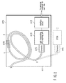
- a total of the 32 respective user optical terminals which are the applicable subjects serving as one embodiment of the fault searching system for an optical line according to the invention respectively insert optical fibers 2 connected to the second optical dividers 51, 52, ⁇ , and 58 into the insides thereof every fours.
- the connector 617C is connected to the terminal portion of the optical fiber 2 at the inside of the user optical terminal 617, and is connected to the light transmitting and receiving unit 617D.
- the light transmitting and receiving unit 617D is connected to the connector 617C connected to the terminal portion of the optical fiber 2, and converts a light which has propagated inside the optical fiber 2 into a digital signal, and outputs the converted digital signal to an unillustrated computer (PC) of a user via the interface circuit 617E.
- PC unillustrated computer
- the light transmitting and receiving unit 617D converts a data signal transmitted from the external unillustrated computer (PC) of the user via the interface circuit 617E into a light signal, and outputs the converted light signal to the second optical divider 55 of FIG. 1 via the connector 617C and the optical fiber 2.
- PC unillustrated computer
- FIG. 3 is a functional block diagram shown for explanation of a configuration of the OTDR 7 used for the embodiment of the fault searching system for an optical line according to the invention.
- a wavelength of an optical pulse emitted from the light source 73 is set at a desired value by an operation of an operator, and data of a repeating period thereof is inputted thereto.
- the operating unit 71 has a function in which a wavelength and a pulse width of an optical pulse emitted from the light source 73 is set at a desired value by an operation of an operator, and data for setting a repeating period thereof to a desired value is inputted thereto.
- the operating unit 71 may have a function such that data for setting a peak level of an optical pulse emitted from the light source 73 so as to be suppressed to a predetermined level or less is inputted by an operation of an operator.
- the wavelength of the optical pulse serving as a test light is set at a value different from the wavelength of a transmission light used in the actual optical communication system, for example, 0.6 ⁇ m.
- the wavelength of the optical pulse serving as a test light outputted from the light source 73 is set at 0.6 ⁇ m. However, it is not limited thereto.
- the optical pulse serving as a test light incident upon the optical fiber 2 which is a measuring subject is made to propagate toward the second optical divider 55 at the inside of the optical fiber 2.
- the backward scattering light or the return light propagates inside the optical fiber 2, and is made to be incident into the OTDR 7 from the one end of the optical fiber 2.
- the optical coupler 74 in the OTDR 7 outputs the backward scattering light or the return light made to be incident into the OTDR 7 to the light receiver 75.
- a photodetector used in the light receiver 75 of the OTDR 7 when an optical pulse with a wavelength of 0.6 ⁇ m (0.63 ⁇ m or 0.65 ⁇ m as well is available) is used as a test light, for example, as shown in FIG. 5, it is assumed that an Si-PIN photodiode which is an Si photodetector indicating satisfactory light receiving sensitivity in a wavelength band which is approximately 0.6 ⁇ m (about 0.4 ⁇ m through about 0.95 ⁇ m), or the like is used.
- the light receiver 75 using the photodetector having such a characteristic hardly indicate light receiving sensitivity with respect to the data transmission lights with the wavelengths of 1.31 ⁇ m and 1.55 ⁇ m used in the FTTH 1, there is no influence of the data transmission lights with respect to the test light.
- the amplifier 76 amplifies the electric signal outputted from the light receiver 75, and outputs the amplified electric signal to the A/D converter 77.
- the processing unit 78 has a function in which after processing in which a trigger synchronized with a pulse inputted from the timing generator 72b is received, and measurement data included in the electric signal outputted from the A/D converter 77 are averaged is carried out, logarithmic conversion is carried out, and a transmission characteristic of the optical fiber 2 with respect to a test light is calculated, and a function of displaying the calculated transmission characteristic of the optical fiber 2 on the display unit 79.
- the display unit 79 displays the transmission characteristic of the optical fiber 2 calculated by the processing unit 78.
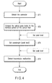
- FIG. 4 is the flowchart shown for explanation of the operations of the fault searching system for an optical line according to the invention.
- the operator detaches the connector 617C connecting the terminal portion of the optical fiber 2 in the user optical terminal 617 and the light transmitting and receiving unit 617D, from the light transmitting and receiving unit 617D as shown by the broken lines in FIG. 2 (step ST1).
- the operator connects the OTDR 7 to the terminal portion of the optical fiber 2 at the inside of the user optical terminal 617 by connecting the OTDR 7 to the connector 617C detached from the light transmitting and receiving unit 617D (step ST2).
- the mechanical splice 617B connecting the optical fibers 2 at the inside of the user optical terminal 617 may be detached, and the OTDR 7 may be connected to one end a of the optical fiber 2 from which the mechanical splice 617B is detached.
- the wavelength of the test light used in the OTDR 7 may be 1.65 ⁇ m which is the same as the wavelength of the test light which is made to be incident from the side of the center station 3 at the time of detecting a fault in the optical fiber 2.
- the reason for this is that, because it is configured such that the test light is made to be incident into the optical fiber 2 without using the connector 617C, there is no influence by the filter for eliminating a light with a wavelength of 1.65 ⁇ m used at the time of a transmission test for the optical fiber 2 which is executed from the side of the center station 3 built-in in the connector 617C.
- the light source 73 equipped in the OTDR 7 may be a variable or a plurality of wavelength light sources which selectively generate a test light having a wavelength greater than or equal to 0.3 ⁇ m and less than 1.3 ⁇ m which is different from the wavelength of the light used for data transmission in the optical line in accordance with setting by the user, or a single light source which generates only a test light having one wavelength thereamong.
- the process of setting the wavelength of the test light can be omitted.
- the wavelength of the test light set in the OTDR 7 is set at an arbitrary value different from 1.3 ⁇ m and 1.55 ⁇ m used for a transmission light, for example, 0.6 ⁇ m, it is not limited thereto.
- the process of setting the wavelength of the test light at step ST3 may be replaced with a process of setting a peak level of an optical pulse which will be a test light so as to be suppressed to a predetermined level (-40 dBm through -50 dBm) or less.
- the peak level of an optical pulse which will be a test light the signal level of the test light at the other user optical terminals or the light receiving portion of the transmission apparatus at the center side is a value within a range of -40 dBm through -50 dBm or less.
- the wavelength of the test light can be set at an arbitrary value regardless of a value included in one of the ranges of being greater than or equal to 0.3 ⁇ m and less than 1.3 ⁇ m, and being greater than 1.65 ⁇ m and less than or equal to 2.0 ⁇ m.
- a process in which the peak level of an optical pulse which will be a test light is set so as to be suppressed to the predetermined level (-40 dBm through -50 dBm) or less may be added to one of the front and rear of the process in which the wavelength of the test light is set at an arbitrary value different from 1.31 ⁇ m and 1.55 ⁇ m used for a transmission lights (step ST3).
- the operator carries out a search for a fault in the optical fiber 2 due to the test light whose wavelength is set at, for example, 0.6 ⁇ m being made to be incident from the connector 617C connected to the terminal portion of the optical fiber 2, by using the OTDR 7 (step ST4).
- the connector 617C provided at the terminal portion of the optical fiber 2 in the user optical terminal 617 is detached from the light transmitting and receiving unit 617D, and the OTDR 7 is connected to the detached connector 617C, and at least one of the test light which has been set at a value different from the wavelength of the light used for data transmission and the test light which has been set so as to be suppressed to the predetermined level (-40 dBm through -50 dBm) or less is made to be incident into the optical fiber 2 via the connector 617C, a fault in the optical fiber 2 laid as an optical line from the user optical terminal 617 up to the second optical divider 55 can be rapidly and exactly searched from the user optical terminal 617 side without affecting the other user optical terminals and the transmission apparatus at the side of the center station.
- the present invention is not limited to the above-described embodiment as is, and structural requirements can be modified and materialized within a range which does not deviate from the gist of the present invention at the practical phase, and various inventions can be sampled and formed due to the plurality of structural requirements which have been disclosed in the above-described embodiment being appropriately combined.
- a fault searching system for an optical line which can rapidly search a fault in an optical fiber laid as an optical line from a user optical terminal up to an optical divider from the user optical terminal side can be provided.
Landscapes
- Physics & Mathematics (AREA)
- Optics & Photonics (AREA)
- Chemical & Material Sciences (AREA)
- Analytical Chemistry (AREA)
- General Physics & Mathematics (AREA)
- Electromagnetism (AREA)
- Engineering & Computer Science (AREA)
- Computer Networks & Wireless Communication (AREA)
- Signal Processing (AREA)
- Optical Communication System (AREA)
- Testing Of Optical Devices Or Fibers (AREA)
Applications Claiming Priority (2)
| Application Number | Priority Date | Filing Date | Title |
|---|---|---|---|
| JP2003193154 | 2003-07-07 | ||
| PCT/JP2004/009464 WO2005003714A1 (fr) | 2003-07-07 | 2004-06-28 | Systeme permettant de controler une trajectoire optique a partir du cote terminal optique afin de detecter un probleme dans la trajectoire |
Publications (2)
| Publication Number | Publication Date |
|---|---|
| EP1650541A1 true EP1650541A1 (fr) | 2006-04-26 |
| EP1650541A4 EP1650541A4 (fr) | 2007-09-05 |
Family
ID=33562446
Family Applications (1)
| Application Number | Title | Priority Date | Filing Date |
|---|---|---|---|
| EP20040746933 Withdrawn EP1650541A4 (fr) | 2003-07-07 | 2004-06-28 | Systeme permettant de controler une trajectoire optique a partir du cote terminal optique afin de detecter un probleme dans la trajectoire |
Country Status (4)
| Country | Link |
|---|---|
| US (1) | US7167237B2 (fr) |
| EP (1) | EP1650541A4 (fr) |
| JP (1) | JP3955875B2 (fr) |
| WO (1) | WO2005003714A1 (fr) |
Families Citing this family (22)
| Publication number | Priority date | Publication date | Assignee | Title |
|---|---|---|---|---|
| WO2007134078A1 (fr) * | 2006-05-08 | 2007-11-22 | Sunrise Telecom Incorporated | Système de profilage de réseau présentant un système de test de couche physique |
| US8014670B2 (en) * | 2007-03-16 | 2011-09-06 | Bigbangwidth Inc. | Method and apparatus for testing and monitoring data communications in the presence of a coupler in an optical communications network |
| JP2009055556A (ja) * | 2007-08-29 | 2009-03-12 | Anritsu Corp | 光モジュール及び光パルス試験器 |
| US8180216B2 (en) * | 2007-12-20 | 2012-05-15 | Verizon Patent And Licensing Inc. | Latency measurement in optical networks |
| CA2737974C (fr) | 2008-10-17 | 2011-11-01 | Exfo Inc. | Procede et appareil de derivation de parametres de trajets optiques dans des reseaux optiques utilisant un otdr a deux longueurs d'onde et un element reflechissant dependant d'une longueur d'onde |
| US8873960B2 (en) | 2008-12-30 | 2014-10-28 | Broadcom Corporation | Techniques for detecting optical faults in passive optical networks |
| US8855491B2 (en) * | 2008-12-30 | 2014-10-07 | Broadcom Corporation | Techniques for protecting passive optical networks |
| EP2209226B1 (fr) * | 2009-01-19 | 2013-07-24 | Nokia Siemens Networks OY | Procédé et dispositif de traitement de signaux dans une unité de réseau optique |
| US8406620B2 (en) * | 2009-07-15 | 2013-03-26 | Pmc Sierra Israel Ltd. | Passive optical network (PON) in-band optical time domain reflectometer (OTDR) |
| EP2567207B1 (fr) | 2010-05-07 | 2017-03-22 | Prysmian S.p.A. | Procédé pour contrôler l'installation correcte d'un câble optique insensible à la courbure et câble optique approprié au procédé associé |
| EP2726837B1 (fr) * | 2011-07-01 | 2018-09-05 | Telefonaktiebolaget LM Ericsson (publ) | Dispositif, noeud à distance et procédés pour supervision de pon. |
| US9118412B2 (en) | 2011-09-27 | 2015-08-25 | Broadcom Corporation | System and method for performing in-band reflection analysis in a passive optical network |
| US8805183B2 (en) | 2012-02-08 | 2014-08-12 | Broadcom Corporation | Optical line terminal (OLT) and method therefore for performing in-band and out-band OTDR measurements |
| US9118982B2 (en) | 2012-02-08 | 2015-08-25 | Broadcom Corporation | Optical line terminal (OLT) optical module adapted to perform optical unit network (ONU) functionality |
| JP6222084B2 (ja) * | 2012-05-18 | 2017-11-01 | 日本電気株式会社 | 光システム |
| JP5485455B2 (ja) * | 2013-07-11 | 2014-05-07 | 中国電力株式会社 | 光ファイバケーブルの接続位置判定方法 |
| JP6196124B2 (ja) * | 2013-10-25 | 2017-09-13 | 東日本電信電話株式会社 | 光ファイバ伝送路モニタシステム |
| WO2017086742A1 (fr) * | 2015-11-20 | 2017-05-26 | 주식회사 쏠리드 | Dispositif auxiliaire de réglage de longueur d'onde et procédé de réglage de longueur d'onde optique de dispositif de réseau optique |
| WO2018017112A1 (fr) * | 2016-07-22 | 2018-01-25 | Halliburton Energy Services, Inc. | Système d'interrogation à fibres optiques pour systèmes de détection multi-distribués |
| CN113078945A (zh) * | 2021-03-26 | 2021-07-06 | 广东电网有限责任公司清远供电局 | 一种输电线路故障定位方法、系统、电子设备和存储介质 |
| EP4430767A1 (fr) * | 2021-11-08 | 2024-09-18 | CommScope Technologies LLC | Module de coexistence pour permettre la réflectométrie optique dans le domaine temporel dans des réseaux optiques |
| US12567904B2 (en) * | 2023-03-28 | 2026-03-03 | Ciena Corporation | Fiber optic cable fault locating apparatus |
Family Cites Families (9)
| Publication number | Priority date | Publication date | Assignee | Title |
|---|---|---|---|---|
| US5270537A (en) * | 1987-08-20 | 1993-12-14 | Santa Barbara Research Center | Laser initiated ordance system optical fiber continuity test |
| JPH0294717A (ja) * | 1988-09-30 | 1990-04-05 | Hitachi Ltd | 光回線終端装置試験方式 |
| CA2031870C (fr) * | 1989-12-11 | 1995-08-08 | Nobuo Tomita | Dispositif et methode de detection des defauts dans les systemes de transmission optiques |
| CA2075961C (fr) * | 1990-02-15 | 1999-01-05 | Peter John Keeble | Appareil de verification optique |
| US5285305A (en) * | 1991-12-12 | 1994-02-08 | At & T Bell Laboratories | Optical communication network with passive monitoring |
| JP3144446B2 (ja) * | 1993-03-01 | 2001-03-12 | 日本電信電話株式会社 | 光パルス試験器 |
| US5815295A (en) * | 1993-03-11 | 1998-09-29 | Lucent Technologies Inc. | Optical communication system with improved maintenance capabilities |
| DE4328486A1 (de) * | 1993-08-24 | 1995-03-02 | Siemens Ag | Überwachung optischer Einfaser-Anschlußleitungen bis zu einer passiven Schnittstelle |
| US6650840B2 (en) * | 1998-03-27 | 2003-11-18 | Lucent Technologies Inc. | Method for identifying faults in a branched optical network |
-
2004
- 2004-06-28 JP JP2005511368A patent/JP3955875B2/ja not_active Expired - Fee Related
- 2004-06-28 US US10/524,067 patent/US7167237B2/en not_active Expired - Fee Related
- 2004-06-28 WO PCT/JP2004/009464 patent/WO2005003714A1/fr not_active Ceased
- 2004-06-28 EP EP20040746933 patent/EP1650541A4/fr not_active Withdrawn
Also Published As
| Publication number | Publication date |
|---|---|
| US7167237B2 (en) | 2007-01-23 |
| WO2005003714A1 (fr) | 2005-01-13 |
| EP1650541A4 (fr) | 2007-09-05 |
| US20050271321A1 (en) | 2005-12-08 |
| JP3955875B2 (ja) | 2007-08-08 |
| JPWO2005003714A1 (ja) | 2006-08-17 |
Similar Documents
| Publication | Publication Date | Title |
|---|---|---|
| US7167237B2 (en) | Test system for optical line which carries out fault search for optical line from user optical terminal side | |
| EP3282242B1 (fr) | Optical time-domain reflectometer | |
| EP1182806B1 (fr) | Système de contrôle d'une voie de transmission optique | |
| US7310134B2 (en) | Device and method of optical fiber condition monitoring in optical networks | |
| CN105721048A (zh) | 一种复合型光纤通信线路故障监测方法及系统 | |
| US8660423B2 (en) | Circuit, system and method for monitoring an optical fiber network | |
| US9383528B2 (en) | Light-receiving module | |
| EP3571789B1 (fr) | Techniques de surveillance de ligne à haute résolution à sortie standardisée et système de communication optique correspondant | |
| CN103036615A (zh) | 光时域检测仪光模块及吉比特无源光网络断点检测系统 | |
| JP6922383B2 (ja) | 光変動位置測定装置、光変調変換器および光変動位置測定方法 | |
| US7411666B2 (en) | Optical time domain reflectometry system at different wavelengths | |
| Kuznia et al. | Novel high-resolution OTDR technology for multi-Gbps transceivers | |
| US20240248000A1 (en) | Pluggable OTDR With Integrated BOSA | |
| US12136945B2 (en) | Optronic transceiver module | |
| US6912046B2 (en) | Instrument measuring chromatic dispersion in optical fibers | |
| CN108337046B (zh) | FTTx终端线路测试仪 | |
| JP2005062172A (ja) | 光線路の障害探索方法 | |
| JP3358436B2 (ja) | 分布型導波路センサ | |
| CN223485199U (zh) | 融合BOTDR和φ-OTDR功能的光信号处理设备 | |
| WO2002016901A2 (fr) | Instrument de mesure de la dispersion chromatique dans des fibres optiques | |
| CN200941616Y (zh) | Sdh传输光缆故障检测系统 | |
| JP2009055556A (ja) | 光モジュール及び光パルス試験器 | |
| CN121252987A (zh) | 一种可以同时实现fbg传感器解调和分布式光纤温度测量的方法及系统 | |
| CN120008481A (zh) | 光纤激光器光纤长度测量系统及其方法 | |
| JPH0227824A (ja) | 光伝送システム故障切り分け試験法 |
Legal Events
| Date | Code | Title | Description |
|---|---|---|---|
| PUAI | Public reference made under article 153(3) epc to a published international application that has entered the european phase |
Free format text: ORIGINAL CODE: 0009012 |
|
| 17P | Request for examination filed |
Effective date: 20050209 |
|
| AK | Designated contracting states |
Kind code of ref document: A1 Designated state(s): DE GB IT |
|
| DAX | Request for extension of the european patent (deleted) | ||
| RBV | Designated contracting states (corrected) |
Designated state(s): DE GB IT |
|
| A4 | Supplementary search report drawn up and despatched |
Effective date: 20070806 |
|
| 17Q | First examination report despatched |
Effective date: 20150326 |
|
| STAA | Information on the status of an ep patent application or granted ep patent |
Free format text: STATUS: THE APPLICATION HAS BEEN WITHDRAWN |
|
| 18W | Application withdrawn |
Effective date: 20150610 |