EP1650921A2 - Synchronisation in einem kohärenten OFDM Empfänger - Google Patents
Synchronisation in einem kohärenten OFDM Empfänger Download PDFInfo
- Publication number
- EP1650921A2 EP1650921A2 EP05023170A EP05023170A EP1650921A2 EP 1650921 A2 EP1650921 A2 EP 1650921A2 EP 05023170 A EP05023170 A EP 05023170A EP 05023170 A EP05023170 A EP 05023170A EP 1650921 A2 EP1650921 A2 EP 1650921A2
- Authority
- EP
- European Patent Office
- Prior art keywords
- correlation
- pilots
- sub
- correlation set
- signal values
- Prior art date
- Legal status (The legal status is an assumption and is not a legal conclusion. Google has not performed a legal analysis and makes no representation as to the accuracy of the status listed.)
- Granted
Links
Images






Classifications
-
- H—ELECTRICITY
- H04—ELECTRIC COMMUNICATION TECHNIQUE
- H04L—TRANSMISSION OF DIGITAL INFORMATION, e.g. TELEGRAPHIC COMMUNICATION
- H04L27/00—Modulated-carrier systems
- H04L27/26—Systems using multi-frequency codes
- H04L27/2601—Multicarrier modulation systems
- H04L27/2647—Arrangements specific to the receiver only
- H04L27/2655—Synchronisation arrangements
- H04L27/2662—Symbol synchronisation
-
- H—ELECTRICITY
- H04—ELECTRIC COMMUNICATION TECHNIQUE
- H04L—TRANSMISSION OF DIGITAL INFORMATION, e.g. TELEGRAPHIC COMMUNICATION
- H04L25/00—Baseband systems
- H04L25/02—Details ; arrangements for supplying electrical power along data transmission lines
- H04L25/0202—Channel estimation
- H04L25/0222—Estimation of channel variability, e.g. coherence bandwidth, coherence time, fading frequency
-
- H—ELECTRICITY
- H04—ELECTRIC COMMUNICATION TECHNIQUE
- H04L—TRANSMISSION OF DIGITAL INFORMATION, e.g. TELEGRAPHIC COMMUNICATION
- H04L27/00—Modulated-carrier systems
- H04L27/26—Systems using multi-frequency codes
- H04L27/2601—Multicarrier modulation systems
- H04L27/2647—Arrangements specific to the receiver only
- H04L27/2655—Synchronisation arrangements
- H04L27/2668—Details of algorithms
- H04L27/2669—Details of algorithms characterised by the domain of operation
- H04L27/2672—Frequency domain
-
- H—ELECTRICITY
- H04—ELECTRIC COMMUNICATION TECHNIQUE
- H04L—TRANSMISSION OF DIGITAL INFORMATION, e.g. TELEGRAPHIC COMMUNICATION
- H04L27/00—Modulated-carrier systems
- H04L27/26—Systems using multi-frequency codes
- H04L27/2601—Multicarrier modulation systems
- H04L27/2647—Arrangements specific to the receiver only
- H04L27/2655—Synchronisation arrangements
- H04L27/2668—Details of algorithms
- H04L27/2681—Details of algorithms characterised by constraints
- H04L27/2686—Range of frequencies or delays tested
-
- H—ELECTRICITY
- H04—ELECTRIC COMMUNICATION TECHNIQUE
- H04L—TRANSMISSION OF DIGITAL INFORMATION, e.g. TELEGRAPHIC COMMUNICATION
- H04L5/00—Arrangements affording multiple use of the transmission path
- H04L5/0001—Arrangements for dividing the transmission path
- H04L5/0003—Two-dimensional division
- H04L5/0005—Time-frequency
- H04L5/0007—Time-frequency the frequencies being orthogonal, e.g. OFDM(A) or DMT
-
- H—ELECTRICITY
- H04—ELECTRIC COMMUNICATION TECHNIQUE
- H04L—TRANSMISSION OF DIGITAL INFORMATION, e.g. TELEGRAPHIC COMMUNICATION
- H04L5/00—Arrangements affording multiple use of the transmission path
- H04L5/003—Arrangements for allocating sub-channels of the transmission path
- H04L5/0048—Allocation of pilot signals, i.e. of signals known to the receiver
Definitions
- the present invention generally relates to digital broadcasting systems. More particular, the present invention relates to frequency or time-frequency correlation-based synchronization for coherent Orthogonal Frequency Division Multiplexing (OFDM) receivers in a multi-carrier digital broadcasting system, such as Digital Video Broadcasting-Terrestrial (DVB-T), Digital Video Broadcasting-Handheld (DVB-H), and Integrated Service Digital Broadcasting-Terrestrial (ISDB-T) system.
- DVD-T Digital Video Broadcasting-Terrestrial
- DVD-H Digital Video Broadcasting-Handheld
- ISDB-T Integrated Service Digital Broadcasting-Terrestrial
- OFDM transmission technique being one kind of the multi-carrier modulation schemes, has been widely applied for modern high-data-rate digital communications and broadcasting due to its extreme efficacy on dealing with the multipath propagation effects.
- the OFDM technique has been adopted by several broadcasting systems such as Digital Audio Broadcasting (DAB), DVB-T, DVB-H and ISDB-T, and, moreover, by local area networks such as the HiperLAN/2 and IEEE 802.11 a/g/n.
- DAB Digital Audio Broadcasting
- DVB-T Digital Audio Broadcasting
- DVB-H DVB-H
- ISDB-T local area networks
- local area networks such as the HiperLAN/2 and IEEE 802.11 a/g/n.
- FFT fast Fourier transform
- the positions of the SPs should be detected and identified by means of a synchronization sequence (or synchronization procedure) at a coherent OFDM receiver.
- a synchronization sequence or synchronization procedure
- the received Radio Frequency (RF) signal is first down converted to the baseband using a tuner and a carrier recovery loop.
- a typical DVB-T/H baseband synchronization sequence 20 is illustrated in Figure 2.
- pre-FFT synchronization is performed in step 21 in which all metrics are derived in time-domain from guard interval correlation.
- the baseband signal is then transformed to the frequency-domain through FFT.
- post-FFT synchronization is performed in frequency-domain in step 22 based on correlating the Continual Pilots (CP) of two consecutive OFDM symbols.
- the pre-FFT and post-FFT synchronization blocks perform the sampling clock, OFDM symbol timing and carrier frequency synchronization.
- TPS Transmission Parameters Signaling
- the detection of the frame boundary is so-called "frame synchronization.”
- the frame synchronization takes a variable synchronization time of 68 ⁇ 136 OFDM symbols, 68 ⁇ 136 T OFDM , which is around 50% ⁇ 70% of the overall synchronization time associated with the total synchronization procedure 20.
- the conventional frame synchronization is considerably time-consuming.
- the receiver may prepare for the required frame synchronization time even longer than the data burst duration of interest. Therefore, the conventional frame boundary detection based SPPs identification (or SPs synchronization) scheme is especially inefficient in the sense of power reduction for receiving the time-sliced DVB-H signals.
- a method for synchronizing pilots contained in symbols received by a receiver in a multicarrier transmission system is provided.
- the pilots have predetermined known values, are posited among data carriers in a frequency dimension containing the received symbols, and have a predetermined position pattern in the frequency dimension.
- the predetermined position pattern may include a finite number of sub-position patterns each corresponding to positions of pilots contained in one of the symbols.
- the method may include: determining at least one correlation set in the frequency dimension between two sub-carriers of at least one symbol; generating a correlation set result in response to each the correlation set; and determining positions of the pilots in the frequency dimension in response to the correlation set results.
- an apparatus for synchronizing pilots contained in symbols received by a receiver in a multicarrier transmission system is provided.
- the pilots have predetermined known values, are posited among data carriers in a frequency dimension containing the received symbols, and have a predetermined position pattern in the frequency dimension.
- the predetermined position pattern may include a finite number of sub-position patterns each corresponding to positions of pilots contained in one of the symbols such that at least one correlation set in the frequency dimension between at least two sub-carriers of at least one symbol can be determined.
- the apparatus includes: a pilots compensator and a signal selector for determining the at least one correlation set; a correlator for generating one correlation set result for each of the correlation set; and a processing unit for determining positions of the pilots in response to the correlation set result.
- an apparatus for synchronizing pilots contained in symbols received by a receiver in a multicarrier transmission system is provided.
- the pilots have predetermined known values, are posited among data carriers in time and frequency dimensions including the received symbols, and have a predetermined position pattern in the time and frequency dimensions.
- the predetermined position pattern may include a finite number of sub-position patterns each corresponding to positions of pilots contained in one of the symbols such that at least one correlation set in the time and frequency dimensions between at least two of the symbols in response to the sub-position pattern can be determined.
- the apparatus include: a pilots compensator and a signal selector for determining the at least one correlation set; a correlator for generating one correlation set result for each the correlation set; and a processing unit for determining positions of the pilots in response to the correlation set result.
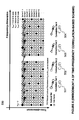
- Fig. 1 is a diagram illustrating positions of SPs in DVB-T/H systems
- Fig. 2 is a diagram illustrating a typical DVB-T/H synchronization sequence (or synchronization procedure);
- Fig. 3 is a diagram illustrating a prior art time correlation-based SPPs identification scheme
- Fig. 4 is a diagram illustrating a prior art power-based SPPs identification scheme
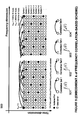
- Fig. 5 is a diagram illustrating positions of SPs for explaining an embodiment in accordance with a time-frequency correlation-based scheme
- Fig. 6 is a block diagram of one example to implement the embodiment of Fig. 5;
- Figs. 7A and 7B are diagrams illustrating the minimum protection ratio (MPR) associated with the time-frequency correlation-based scheme of the present invention, the conventional time correlation-based and power-based schemes upon simulation results;
- MPR minimum protection ratio
- Fig. 8 is a diagram illustrating positions of SPs for explaining another embodiment in accordance with a time-frequency correlation-based scheme
- Fig. 9 is a diagram illustrating positions of SPs for explaining an embodiment in accordance with a frequency correlation-based scheme
- Fig. 10 is a block diagram of one example to implement the embodiment of Fig. 9;
- Fig. 11 is a diagram illustrating positions of SPs for explaining another embodiment in accordance with a frequency correlation-based scheme.
- Fig. 12 is a diagram illustrating an application of the present invention in the synchronization procedure of DVB-T/H receivers.
- a frequency or time-frequency correlation-based scheme that exploits frequency or time-frequency correlation characteristics of the SPs is provided for robust SP synchronization without TPS synchronization. It is to be understood that the present invention may be implemented in various forms of hardware, software, firmware, special purpose processors, or a combination thereof.
- SPPs are designated by solid circles which appear as regular position pattern.
- the position pattern associated with the SPPs further comprises of four sub-position pattems: 101, 102, 103 and 104 in Fig. 1, wherein each sub-position pattern in the time-dimension will repeat once for every four OFDM symbols.
- the four sub-position patterns 101, 102, 103 and 104 are denoted as sub-position patterns 1, 2, 3, and 4, respectively.
- R l,k is defined as the received baseband signal on the kth sub-carrier of the l th OFDM symbol.
- R 1,0 the signal in the position 120
- R 9,18 the signal in the position 140
- Fig. 3 is a diagram illustrating a prior art time correlation-based SPPs identification scheme as disclosed in L. Schwoerer and J. Vesma, "Fast Scattered Pilot Synchronization for DVB-T and DVB-H," Proc. 8 th International OFDM Workshop, Hamburg, Germany, Sept. 24-25, 2003.
- four sets of correlation are performed for the four possible SPPs along the time-dimension and both the current and the last fourth OFDM symbols have to be accessed for each correlation set.
- ⁇ p 0 p max R l , 12 p + 3 ( i ⁇ 1 ) ⁇ R l ⁇ 4 , 12 p + 3 ( i ⁇ 1 ) ⁇
- Fig. 4 is a diagram illustrating another prior art power-based SPPs identification scheme as disclosed in L. Schwoerer, "Fast Pilot Synchronization Schemes for DVB-H," Proc. Wireless and Optical Communications, Banff, Canada, July 8-10, 2004, pp. 420-424.
- four sets of power estimators are performed for the four possible SPPs and only the current OFDM symbol needs to be accessed for each set of power estimators.
- the power of SPs is higher than the data symbols.
- This approach exploits features of the SPs themselves instead of the TPS such that the time needed for SPPs identification is reduced to 1 T OFDM .
- the power-based SPPs identification scheme is quite sensitive to noise effects and ill-conditioned channel effects (e.g., echo in single-frequency networks (SFN)).
- the present invention sets forth a frequency or time-frequency correlation-based scheme for the purpose of fast and robust SPs synchronization for OFDM receivers.
- Fig. 5 a diagram illustrating the SPPs for explaining a time-frequency correlation-based scheme in accordance with one embodiment of the present invention is depicted schematically. As shown in Fig. 5, four correlation sets C 1 ( I ), C 2 ( I ), C 3 ( I ), C 4 ( I ) (i.e., 501, 502, 503 and 504) in view of two adjacent OFDM symbols are used for SPPs identification.
- C 1 ( l )
- ⁇ p 0 p max ( R l , 12 p + 3 ⁇ P 12 p + 3 ) ⁇ ( R l ⁇ 1 , 12 p ⁇ ⁇ P 12 p ⁇ )
- C 2 ( l )
- ⁇ p 0 p max ( R l , 12 p + 6 ⁇ P 12 p + 6 ) ⁇ ( R l ⁇ 1 , 12 p + 3 ⁇ ⁇ P 12 p + 3 ⁇ )
- C 3 ( l )
- ⁇ p 0 p max ( R l , 12 p + 9 ⁇ P 12 p + 9 ) ⁇ ( R l ⁇ 1 , 12 p + 6 ⁇ ⁇ P 12 p + 6 ⁇ )
- C 4 ( l )
- ⁇ p 0 p max
- the time-frequency correlation-based scheme of the present invention basically comprises an SP compensator and signal selector 630, four correlators 660A, 660B, 660C and 660D, and a judgment or processing block 670.
- the SP compensator and signal selector 630 is employed to obtain sub-signals 640A, 640B, 640C, 640D, 650A, 650B, 650C, and 650D, which are associated to ( R l, 12 p+3 ⁇ P 12 p+ 3 ), ( R l, 12 p+ 6 ⁇ P 12 p+ 6 ), ( R l, 12 p+ 9 ⁇ P 12 p+9 ), ( R l, 12 p+ 12 ⁇ P 12 p+ 12 ), ( R l- 1,12 p ⁇ P 12 p ), ( R l- 1,12 p+ 3 ⁇ P 12 p+ 3 ), ( R l- 1,12 p+ 6 ⁇ P 12 p +6 ) and ( R l- 1,12 p +9 ⁇ P 12 p +9 ), respectively, wherein p ⁇ Z ⁇ ⁇ 0, 1, 2,..., p max ⁇ .
- the SP compensator and signal selector 630 includes a buffer to receive the signals 610 for storing the signals of the previous OFDM symbol I-1.
- Sub-signals 640A and 650A are applied to the correlator 660A
- sub-signals 640B and 650B are applied to the correlator 660B
- sub-signals 640C and 650C are applied to the correlator 660C
- sub-signals 640D and 650D are applied to the correlator 660D.
- the correlators 660A, 660B, 660C and 660D are employed to compute four correlation set results 501, 502, 503 and 504, which are associated to the correlation sets C 1 ( I ), C 2 ( I ), C 3 ( I ) and C 4 ( I ) as depicted in Fig. 5, respectively.
- the correlator 660A includes a complex conjugate function to generate the conjugate part of a signal, a complex multiplier and an accumulator, while correlators 660B, 660C and 660D can be implemented the same.
- the four correlation set results 501, 502, 503 and 504 are all supplied to a judgment or processing block 670 to determine the maximum thereof and generate a judgment or processing result 680 as SPP ( l ) indicating the sub-position pattern exhibited by the SPs in the current /th OFDM symbol accordingly.
- the judgment or processing unit 680 includes a peak detector or a comparator so as to determine the maximum of correlation set results 501, 502, 503 and 504.
- the time-frequency correlation-based scheme of this example may require only two adjacent OFDM symbols in order to compute the correlation set results C 1 ( I ), C 2 ( I ), C 3 ( I ), C 4 ( I ) and then determine the maximum thereof to be associated with the judgment or processing result 680 indicating the correct SPPs of the current symbol.
- the time-frequency correlation-based scheme of this example hence benefits not only the ability of fast synchronization speed but also the robustness against Doppler effects due to less stringent requirement on the channel coherence time.
- the time-frequency correlation-based scheme of this example may be less sensitive to ScFO effects than the conventional time correlation-based scheme.
- the time-frequency correlation-based scheme of this example may provide robustness against noise effects due to the correlation gain at the cost of slightly longer synchronization time 2T OFDM .
- another advantage of the example over both time correlation-based and power-based schemes is that the time-frequency correlation-based scheme is free from the correlation-interference caused by CP defined in DVB-T/H wherein the CP are continuously located at the same subset S cP of subcarriers over all OFDM symbols with S CP ⁇ S SP .
- FIGs 7A and 7B Some of the simulation results (for 8k mode in DVB-T/H with a guard interval of 1/4 useful symbol length) are shown in Figures 7A and 7B for supporting the efficacy and robustness of the time-frequency correlation-based scheme in one example.
- Figs. 7A and 7B plot the minimum protection ratio (MPR), a performance index used by L. Schwoerer, "Fast Pilot Synchronization Schemes for DVB-H," Proc. Wireless and Optical Communications, Banff, Canada, July 8-10, 2004, pp. 420-424.
- MPR minimum protection ratio
- the MPRs for the conventional time correlation-based and power-based schemes are defined in a similar way with C i ( n ) ( l ) replaced by T i ( n ) ( l ) and E i ( n ) ( l ) respectively. It is noted that the higher the MPR value the more robust the performance of the SPPs identification scheme, wherein MPR ⁇ 1 implies at least one erroneous detection of the SPPs exists over the 1000 independent runs.
- curves 70A and 70B are associated with the time-frequency correlation-based scheme of one example, wherein curves 72A and 72B correspond to the conventional time correlation-based scheme and curves 74A and 74b correspond to the conventional power-based scheme.
- both the time-frequency correlation-based scheme of one example and the conventional time correlation-based scheme are uniformly more robust against noise effects than the conventional power-based scheme due to the correlation gain.
- the time-frequency correlation-based scheme in some examples may outperform the conventional time correlation-based scheme under higher C/N because the latter may suffer from the correlation-interference due to CP that dominates the performance for low noise condition.
- the conventional power-based scheme is as expected insensitive to Doppler effects and the time-frequency correlation-based scheme may be more robust against Doppler effects than the conventional time correlation-based scheme whose performance is significantly degraded for Doppler frequency larger than 60 Hz because the latter requires longer coherence time.
- the time-frequency correlation-based scheme may outperform the conventional time correlation-based and power-based schemes in view of robustness against both Doppler and noise effects.
- the time-frequency correlation-based scheme can further provide a flexible design for the trade-off between hardware cost and synchronization time in some examples.
- Fig. 8 a diagram illustrating the SPPs for explaining another embodiment in accordance with the time-frequency correlation-based scheme. As compared with the embodiment of Fig. 5, this embodiment makes use of only one correlation set, for example, C 1 ( I ), to determine the correct SPP of the current symbol. If the time-frequency correlation-based scheme of Fig. 8 is implemented in the same manner as Fig. 6, three sets of correlators 660B, 660C and 660D can be omitted with certain modification on the SPPs identification scheme.
- the judgment or processing block 670 should include a detector provided with threshold detection approach so that the current SPPs are identified as sub-position pattern 2 if C 1 ( I ) is larger than a threshold value.
- the correlator 660A should be performed four times to obtain C 1 ( I ), C 1 ( I -1), C 1 ( I -2) and C 1 ( I -3) using the ( I,I -1), ( I -1, I -2), ( I -2, I -3) and ( I -3, I -4) OFDM symbols pairs, respectively.
- a frequency correlation-based scheme may be implemented.
- the implementation may be based on the characteristics of the SPPs noted above and, in some examples, may be used for providing fast and robust SPs synchronization for OFDM receivers.
- the implementation may be used to increase the processing speed of an OFDM receiver and improve SP synchronization.
- one correlation set such as F 1 ( I ), F 2 ( I ), F 3 ( I ) and F 4 ( I ) illustrated as in Fig. 9, may be used to determine the correct SPP of the current symbol.
- ⁇ p 0 p max ( R l , 12 p ⁇ P 12 p ) ⁇ ( R l , 12 ( p + 1 ) ⁇ ⁇ P 12 ( p + 1 ) ⁇ )
- F 2 ( l )
- ⁇ p 0 p max ( R l , 12 p + 3 ⁇ P 12 p + 3 ) ⁇ ( R l , 12 ( p + 1 ) + 3 ⁇ ⁇ P 12 ( p + 1 ) + 3 ⁇ )
- F 3 ( l )
- ⁇ p 0 p max ( R l , 12 p + 6 ⁇ P 12 p + 6 ) ⁇ ( R l , 12 ( p + 1 ) + 6 ⁇ ) + 6 ⁇ )
- Fig. 10 illustrates an exemplary block diagram for implementing a frequency correlation-based scheme.
- the frequency correlation-based scheme may include an SP compensator and signal selector 1030, four correlators 1060A, 1060B, 1060C and 1060D, and a judgment or processing block 1070.
- the SP compensator and signal selector 1030 may be employed to obtain sub-signals 1040A, 1040B, 1040C, 1040D, and 1050D, which are associated to ( R l ,12 p ⁇ P 12 p ), ( R l ,12 p +3 ⁇ P 12 p +3 ), ( R l ,12 p +6 ⁇ P 12 p +6 ), ( R l ,12 p +9 ⁇ P 12 p +9 ), ( R l ,12( p +1) ⁇ P 12( p +1) ), ( R l ,12( p +1)+3 ⁇ P 12( p +1)+3 ), ( R l ,12( p +1)+6 ⁇ P 12( p +1)+6 ), and ( R l ,12( p +1)+9 ⁇ P 12( p +1)+9 ), wherein p ⁇ Z ⁇ 0,1, 2,..., p
- sub-signal 1040A and 1050A may be applied to correlator 1060A; sub-signal 1040B and 1050B may be applied to correlator 1060B; sub-signal 1040C and 1050C may be applied to correlator 1060C; sub-signal 1040D and 1050D may be applied to correlator 1060D.
- Correlators 1060A, 1060B, 1060C and 1060D may be used to compute four correlation set results 901, 902, 903 and 904, which are respectively correlated to correlation sets F 1 ( I ), F 2 ( I ), F 3 ( I ) and F 4 ( I ) illustrated in Fig. 9.
- correlator 660A may include a complex conjugate function to generate the conjugate part of a signal, a complex multiplier, and an accumulator
- correlators 660B, 660C and 660D may be implemented in the same or similar manner.
- correlation set results 901, 902, 903 and 904 may be submitted to judgment or processing block 1070 to determine the maximum among them and generate a judgment or processing result 1080 as SPP ( l ), which may indicate the sub-position pattern of the SP for the current /th OFDM symbol accordingly.
- the judgment or processing unit 1080 may include a peak detector or a comparator so as to determine the maximum of correlation set results 901, 902, 903 and 904. It is noted that some of the sub-signals 1040A, 1040B, 1040C, 1040D, 1050A, 1050B, 1050C, and 1050D may appear at different times. Accordingly, one of ordinary skill in the related art, such as in the field of time-sharing or resource-sharing hardware design, may be able obtain the four correlation set results 901, 902, 903 and 904 with a less number of correlators, such as with only one correlator 1060A.
- the frequency correlation-based scheme in these examples requires only one OFDM symbol in order to compute the correlation set results F 1 ( I ), F 2 ( I ), F 3 ( I ), F 4 ( I ) and determine the maximum of the results.
- the judgment or processing result 1080 may identify the correct SPPs of the current symbol. Accordingly, a frequency correlation-based scheme may improve the ability of fast synchronization speed and/or improve the robustness against Doppler effects due to a less stringent requirement on the channel coherence time. In addition, a frequency correlation-based scheme may be less sensitive to ScFO effects when compared with conventional time correlation-based schemes.
- the frequency correlation-based scheme when compared with the conventional power-based scheme of the required synchronization time T OFDM , the frequency correlation-based scheme may provide robustness against noise effects due to the correlation gain at the cost of slightly longer synchronization time 2T OFDM . Furthermore, a frequency correlation-based scheme may be free from the correlation-interference caused by CP defined in DVB-T/H.
- Fig. 11 illustrates another example of implementing a frequency correlation-based scheme. Referring to Fig. 11, this example uses only one correlation, such as F1(I) to determine the correct SPP of a current symbol.
- F1(I) the correlation that uses only one correlation, such as F1(I) to determine the correct SPP of a current symbol.
- the SPP identification components may be modified to remove three correlators 1060B, 1060C, and 1060D.
- judgment or processing block 1070 include a threshold value detecting device, such that when F1 (I) is larger than a certain threshold, the current SPP may be identified as sub-position pattern 1.
- any combination of two or three of the correlation sets F 1 (I), F 2 (I), F 3 (I) and F 4 (I) can be used in a similar way as a variation of the examples in Fig. 11 to reduce the number of correlators required with increased synchronization time of 1 ⁇ 4 T OFDM .
- Fig. 12 is a diagram illustrating an application of the present invention in the synchronization procedure of DVB-T/H receivers. Compared to the typical DVB-T/H synchronization sequence shown in Fig. 2, SPPs required by channel estimation are identified through the present invention without TPS synchronization.
- the specification may have presented the method and/or process of the present invention as a particular sequence of steps. However, to the extent that the method or process does not rely on the particular order of steps set forth herein, the method or process should not be limited to the particular sequence of steps described. As one of ordinary skill in the art would appreciate, other sequences of steps may be possible. Therefore, the particular order of the steps set forth in the specification should not be construed as limitations on the claims. In addition, the claims directed to the method and/or process of the present invention should not be limited to the performance of their steps in the order written, and one skilled in the art can readily appreciate that the sequences may be varied and still remain within the spirit and scope of the present invention.
Landscapes
- Engineering & Computer Science (AREA)
- Computer Networks & Wireless Communication (AREA)
- Signal Processing (AREA)
- Power Engineering (AREA)
- Synchronisation In Digital Transmission Systems (AREA)
- Mobile Radio Communication Systems (AREA)
- Circuits Of Receivers In General (AREA)
- Synchronizing For Television (AREA)
Applications Claiming Priority (2)
| Application Number | Priority Date | Filing Date | Title |
|---|---|---|---|
| US62072504P | 2004-10-22 | 2004-10-22 | |
| US11/153,105 US20060088133A1 (en) | 2004-10-22 | 2005-06-15 | Time-frequency correlation-based synchronization for coherent OFDM receiver |
Publications (3)
| Publication Number | Publication Date |
|---|---|
| EP1650921A2 true EP1650921A2 (de) | 2006-04-26 |
| EP1650921A3 EP1650921A3 (de) | 2007-12-12 |
| EP1650921B1 EP1650921B1 (de) | 2010-12-08 |
Family
ID=35629101
Family Applications (1)
| Application Number | Title | Priority Date | Filing Date |
|---|---|---|---|
| EP05023170A Expired - Lifetime EP1650921B1 (de) | 2004-10-22 | 2005-10-24 | Synchronisation in einem kohärenten OFDM Empfänger |
Country Status (6)
| Country | Link |
|---|---|
| US (1) | US20060088133A1 (de) |
| EP (1) | EP1650921B1 (de) |
| JP (1) | JP4295755B2 (de) |
| AT (1) | ATE491295T1 (de) |
| DE (2) | DE102005045361A1 (de) |
| TW (1) | TWI273807B (de) |
Cited By (22)
| Publication number | Priority date | Publication date | Assignee | Title |
|---|---|---|---|---|
| WO2008027616A1 (en) * | 2006-08-31 | 2008-03-06 | Sony Ericsson Mobile Communications Ab | Mitigating interference caused by intermittent signal transmission in a multicarrier receiver |
| WO2009143860A1 (en) * | 2008-05-28 | 2009-12-03 | Nokia Siemens Networks Oy | Method and apparatus for providing pilot signals in ofdm frames |
| EP2131541A1 (de) | 2008-06-04 | 2009-12-09 | Sony Corporation | Neue Rahmen- und Trainingsmusterstruktur für Mehrträgersysteme |
| EP2131520A1 (de) | 2008-06-04 | 2009-12-09 | Sony Corporation | Neue Rahmen- und Trainingsmusterstruktur für Mehrträgersysteme |
| CN101651652A (zh) * | 2008-08-14 | 2010-02-17 | 索尼株式会社 | 用于多载波系统的新的帧和信令模式结构 |
| EP2154848A1 (de) * | 2008-08-14 | 2010-02-17 | Sony Corporation | Neue Rahmen- und Signalisierungsmusterstruktur für Mehrträgersysteme |
| EP2154849A1 (de) | 2008-08-14 | 2010-02-17 | Sony Corporation | Neue Rahmen- und Signalisierungsmusterstruktur für Mehrträgersysteme |
| EP2154850A1 (de) | 2008-08-14 | 2010-02-17 | Sony Corporation | Neue Rahmen- und Signalisierungsmusterstruktur für Mehrträgersysteme |
| EP2161893A1 (de) * | 2008-09-08 | 2010-03-10 | Sony Corporation | Neue Rahmen- und Datenmusterstruktur für Mehrträgersysteme |
| EP2161889A1 (de) * | 2008-09-08 | 2010-03-10 | Sony Corporation | Neue Rahmen- und Datenmusterstruktur für Mehrträgersysteme |
| EP2175597A1 (de) * | 2008-10-09 | 2010-04-14 | Sony Corporation | Neue Rahmen- und Datenmusterstruktur für Mehrträgersysteme |
| EP2175600A1 (de) * | 2008-10-09 | 2010-04-14 | Sony Corporation | Neue Rahmen- und Datenmusterstruktur für Mehrträgersysteme |
| US8089858B2 (en) | 2008-08-14 | 2012-01-03 | Sony Corporation | Frame and signalling pattern structure for multi-carrier systems |
| US8194529B2 (en) | 2008-09-08 | 2012-06-05 | Sony Corporation | Frame and data pattern structure for multi-carrier systems |
| US8203929B2 (en) | 2008-10-09 | 2012-06-19 | Sony Corporation | Frame and data pattern structure for multi-carrier systems |
| US8295311B2 (en) | 2006-09-11 | 2012-10-23 | Telefonaktiebolaget Lm Ericsson (Publ) | Detection of time-frequency hopping patterns |
| CN103023631A (zh) * | 2008-08-14 | 2013-04-03 | 索尼株式会社 | 用于多载波系统的新的帧和信令模式结构 |
| US8687716B2 (en) | 2008-06-04 | 2014-04-01 | Sony Corporation | Digital signal transmission and reception |
| TWI478546B (zh) * | 2007-08-01 | 2015-03-21 | Nokia Siemens Networks Oy | 資源配置技術 |
| TWI487336B (zh) * | 2012-04-24 | 2015-06-01 | Mstar Semiconductor Inc | 相位誤差修正裝置及相位誤差修正方法 |
| US9182246B2 (en) | 2010-01-25 | 2015-11-10 | Sony Corporation | Method, system and sensor for identifying an electrical device connected to a mains grid |
| TWI554065B (zh) * | 2013-08-09 | 2016-10-11 | Alcatel Lucent | Communication Information Exchange Device and Method in Multi - point Collaboration |
Families Citing this family (15)
| Publication number | Priority date | Publication date | Assignee | Title |
|---|---|---|---|---|
| JP4584756B2 (ja) * | 2005-04-07 | 2010-11-24 | 日本放送協会 | パイロット信号検出装置及び方法 |
| JP4892547B2 (ja) * | 2006-03-17 | 2012-03-07 | パナソニック株式会社 | 無線通信基地局装置およびパイロット配置方法 |
| KR101233604B1 (ko) * | 2006-07-04 | 2013-02-14 | 가부시키가이샤 히다치 고쿠사이 덴키 | 수신 장치 |
| JP4724677B2 (ja) * | 2006-10-31 | 2011-07-13 | Okiセミコンダクタ株式会社 | 周波数オフセット検出器とofdmシンボル検出器 |
| US7899140B2 (en) | 2007-12-17 | 2011-03-01 | Newport Media, Inc. | Scattered pilot correlation in DVB-H systems |
| JP4505517B2 (ja) * | 2008-03-17 | 2010-07-21 | 株式会社日立国際電気 | 受信装置 |
| JP5838235B2 (ja) * | 2008-06-04 | 2016-01-06 | ソニー ドイチュラント ゲゼルシャフト ミット ベシュレンクテル ハフツング | マルチキャリアシステムのための新たなフレーム及び信号パターン構造 |
| US8116419B2 (en) * | 2008-07-14 | 2012-02-14 | Alcatel Lucent | Methods and apparatuses for estimating time delay and frequency offset in single frequency networks |
| JP5212638B2 (ja) * | 2008-11-21 | 2013-06-19 | ネッツエスアイ東洋株式会社 | 電力線搬送通信システム及び電力線搬送通信装置 |
| CN101800719B (zh) * | 2009-02-10 | 2013-03-20 | 扬智科技股份有限公司 | 离散导频同步方法与装置及其通信系统 |
| JP5540733B2 (ja) * | 2010-01-29 | 2014-07-02 | 富士通セミコンダクター株式会社 | 信号処理装置,信号処理方法とそれを有する受信装置 |
| JP5511434B2 (ja) * | 2010-02-23 | 2014-06-04 | 三菱電機株式会社 | フレーム同期装置および受信装置 |
| US9215019B2 (en) | 2012-02-13 | 2015-12-15 | Alcatel Lucent | Method and apparatus for interference cancellation in hybrid satellite-terrestrial network |
| US9137083B1 (en) * | 2014-04-17 | 2015-09-15 | Freescale Semiconductor, Inc. | Synchronization and frequency correction for a receiver |
| US9253007B1 (en) * | 2014-10-13 | 2016-02-02 | Silicon Laboratories Inc. | Methods and systems for rapid detection of digital content within RF signals |
Family Cites Families (21)
| Publication number | Priority date | Publication date | Assignee | Title |
|---|---|---|---|---|
| KR100226708B1 (ko) * | 1997-06-26 | 1999-10-15 | 전주범 | 직교분할대역 채널 등화기의 계수 메모리를 위한 어드레스 발생 장치 |
| KR100314353B1 (ko) * | 1998-04-28 | 2001-12-28 | 전주범 | 직교분할대역수신시스템 |
| DE19948383A1 (de) * | 1999-10-07 | 2001-04-12 | Rohde & Schwarz | Verfahren zum empfangsseitigen Bestimmen der Nutzdatenkonstellation eines nach dem DVB-T-Standard modulierten Multiträger-Signals für die Berechnung der Restträgerleistung bzw. Verbesserung der Demodulation |
| JP2002009728A (ja) * | 2000-06-23 | 2002-01-11 | Hitachi Kokusai Electric Inc | 直交周波数分割多重変調伝送装置 |
| EP1178640B1 (de) * | 2000-08-01 | 2006-05-24 | Sony Deutschland GmbH | Vorrichtung und Verfahren zur Kanalschätzung eines OFDM-system |
| JP3776716B2 (ja) * | 2000-11-17 | 2006-05-17 | 株式会社東芝 | 直交周波数分割多重伝送信号受信装置 |
| US8170513B2 (en) * | 2002-10-25 | 2012-05-01 | Qualcomm Incorporated | Data detection and demodulation for wireless communication systems |
| JP3642784B2 (ja) * | 2002-10-28 | 2005-04-27 | 三菱電機株式会社 | ダイバーシチ受信装置およびダイバーシチ受信方法 |
| FR2851384B1 (fr) * | 2003-02-17 | 2009-12-18 | Wavecom | Procede de transmission de donnees radio, signal, systeme et dispositifs correspondant. |
| US8483189B2 (en) * | 2003-03-10 | 2013-07-09 | Panasonic Corporation | OFDM signal transmission method, transmission apparatus, and reception apparatus |
| US7580466B2 (en) * | 2003-05-12 | 2009-08-25 | Mitsubishi Denki Kabushiki Kaisha | Demodulation device and demodulation method |
| US20040228270A1 (en) * | 2003-05-13 | 2004-11-18 | Hou-Shin Chen | Method of processing an OFDM signal and OFDM receiver using the same |
| KR100555722B1 (ko) * | 2003-05-20 | 2006-03-03 | 삼성전자주식회사 | 다중 반송파 수신 시스템의 정수배 주파수 옵셋 추정 장치및 그의 정수배 주파수 옵셋 추정방법 |
| JP3662579B2 (ja) * | 2003-05-30 | 2005-06-22 | 三菱電機株式会社 | Ofdm信号受信装置及びofdm信号受信方法 |
| AU2003238128A1 (en) * | 2003-06-30 | 2005-01-13 | Nokia Corporation | Faster fine timing operation in multi-carrier system |
| KR100606105B1 (ko) * | 2003-07-04 | 2006-07-28 | 삼성전자주식회사 | 다중 접속 방식을 사용하는 이동 통신 시스템의 셀 탐색장치 및 방법 |
| EP1507378B1 (de) * | 2003-08-14 | 2012-10-24 | Sony Deutschland GmbH | Rahmen- und Frequenzsynchronisation für OFDM |
| AU2003262613A1 (en) * | 2003-09-22 | 2005-04-11 | Nokia Corporation | Method, system and receiver in receiving a multi-carrier transmission |
| EP1521413A3 (de) * | 2003-10-01 | 2009-09-30 | Panasonic Corporation | Mehrträgerempfang mit Kanalschätzung und Entzerrung |
| AU2003267470A1 (en) * | 2003-10-03 | 2005-04-21 | Nokia Corporation | Method, system and receiver for receiving a multi-carrier transmission |
| KR100507541B1 (ko) * | 2003-12-19 | 2005-08-09 | 삼성전자주식회사 | 직교주파수분할다중접속 시스템에서의 데이터 및 파일롯할당 방법 과 그를 이용한 송신 방법 및 그 장치, 수신방법과 그 장치 |
-
2005
- 2005-06-15 US US11/153,105 patent/US20060088133A1/en not_active Abandoned
- 2005-09-22 DE DE102005045361A patent/DE102005045361A1/de not_active Withdrawn
- 2005-10-24 DE DE602005025189T patent/DE602005025189D1/de not_active Expired - Lifetime
- 2005-10-24 AT AT05023170T patent/ATE491295T1/de not_active IP Right Cessation
- 2005-10-24 TW TW094137166A patent/TWI273807B/zh not_active IP Right Cessation
- 2005-10-24 JP JP2005308748A patent/JP4295755B2/ja not_active Expired - Lifetime
- 2005-10-24 EP EP05023170A patent/EP1650921B1/de not_active Expired - Lifetime
Cited By (70)
| Publication number | Priority date | Publication date | Assignee | Title |
|---|---|---|---|---|
| US7899106B2 (en) | 2006-08-31 | 2011-03-01 | Sony Ericsson Mobile Communications Ab | Mitigating OFDM receiver interference caused by intermittent signal transmission |
| WO2008027616A1 (en) * | 2006-08-31 | 2008-03-06 | Sony Ericsson Mobile Communications Ab | Mitigating interference caused by intermittent signal transmission in a multicarrier receiver |
| US8295311B2 (en) | 2006-09-11 | 2012-10-23 | Telefonaktiebolaget Lm Ericsson (Publ) | Detection of time-frequency hopping patterns |
| TWI478546B (zh) * | 2007-08-01 | 2015-03-21 | Nokia Siemens Networks Oy | 資源配置技術 |
| WO2009143860A1 (en) * | 2008-05-28 | 2009-12-03 | Nokia Siemens Networks Oy | Method and apparatus for providing pilot signals in ofdm frames |
| US8824575B2 (en) | 2008-05-28 | 2014-09-02 | Nokia Siemens Networks Oy | Method and apparatus for providing pilot signals in OFDM frames |
| TWI455536B (zh) * | 2008-06-04 | 2014-10-01 | Sony Corp | 用於多載波系統的新訊框結構 |
| RU2498516C2 (ru) * | 2008-06-04 | 2013-11-10 | Сони Корпорейшн | Новая структура фрейма и тренировочная структура для систем с множеством несущих |
| US9077598B2 (en) | 2008-06-04 | 2015-07-07 | Sony Corporation | Digital signal transmission and reception |
| TWI491212B (zh) * | 2008-06-04 | 2015-07-01 | Sony Corp | 用於多載波系統的新訊框和訓練樣型結構 |
| EP2131541A1 (de) | 2008-06-04 | 2009-12-09 | Sony Corporation | Neue Rahmen- und Trainingsmusterstruktur für Mehrträgersysteme |
| US8897120B2 (en) | 2008-06-04 | 2014-11-25 | Sony Corporation | Frame and training pattern structure for multi-carrier systems |
| TWI455537B (zh) * | 2008-06-04 | 2014-10-01 | Sony Corp | 用於多載波系統的新訊框和發訊樣型結構 |
| EP2131540A1 (de) | 2008-06-04 | 2009-12-09 | Sony Corporation | Neuartige Rahmenstruktur für Mehrträgersysteme |
| EP2131520A1 (de) | 2008-06-04 | 2009-12-09 | Sony Corporation | Neue Rahmen- und Trainingsmusterstruktur für Mehrträgersysteme |
| US8792322B2 (en) | 2008-06-04 | 2014-07-29 | Sony Corporation | Frame and signalling pattern structure for multi-carrier systems |
| EP2544421A3 (de) * | 2008-06-04 | 2014-02-26 | Sony Corporation | Neue Rahmen- und Signalisierungsmusterstruktur für Mehrträgersysteme |
| US8687716B2 (en) | 2008-06-04 | 2014-04-01 | Sony Corporation | Digital signal transmission and reception |
| EP2512059A3 (de) * | 2008-06-04 | 2014-02-26 | Sony Corporation | Neue Rahmen- und Signalisierungsmusterstruktur für Mehrträgersysteme |
| AU2009201904B8 (en) * | 2008-06-04 | 2014-01-30 | Sony Corporation | New frame and training pattern structure for multi-carrier systems |
| EP2131542A1 (de) | 2008-06-04 | 2009-12-09 | Sony Corporation | Neue Rahmen- und Signalisierungsmusterstruktur für Mehrträgersysteme |
| AU2009201904A8 (en) * | 2008-06-04 | 2014-01-30 | Sony Corporation | New frame and training pattern structure for multi-carrier systems |
| US8121017B2 (en) | 2008-06-04 | 2012-02-21 | Sony Corporation | Frame and signaling pattern structure for multi-carrier systems |
| EP2134044A1 (de) | 2008-06-04 | 2009-12-16 | Sony Corporation | Neue Rahmen- und Signalisierungsmusterstruktur für Mehrträgersysteme |
| AU2009201983B2 (en) * | 2008-06-04 | 2014-01-23 | Sony Corporation | New frame and signalling pattern structure for multi-carrier systems |
| US8274878B2 (en) | 2008-06-04 | 2012-09-25 | Sony Corporation | Frame and training pattern structure for multi-carrier systems |
| EP2131519A1 (de) | 2008-06-04 | 2009-12-09 | Sony Corporation | Neuartige Rahmenstruktur für Mehrträgersysteme |
| AU2009201904B2 (en) * | 2008-06-04 | 2014-01-16 | Sony Corporation | New frame and training pattern structure for multi-carrier systems |
| EP2541828A3 (de) * | 2008-06-04 | 2013-03-06 | Sony Corporation | Neue Rahmen- und Signalisierungsmusterstruktur für Mehrträgersysteme |
| CN101599945B (zh) * | 2008-06-04 | 2014-01-01 | 索尼株式会社 | 用于多载波系统的新的帧与信令模式结构 |
| US8089858B2 (en) | 2008-08-14 | 2012-01-03 | Sony Corporation | Frame and signalling pattern structure for multi-carrier systems |
| US8804479B2 (en) | 2008-08-14 | 2014-08-12 | Sony Corporation | Frame and signalling pattern structure for multi-carrier systems |
| CN103023631A (zh) * | 2008-08-14 | 2013-04-03 | 索尼株式会社 | 用于多载波系统的新的帧和信令模式结构 |
| RU2504075C2 (ru) * | 2008-08-14 | 2014-01-10 | Сони Корпорейшн | Новая структура кодовой комбинации для передачи фреймов и сигналов в системе с множеством несущих |
| CN101651651B (zh) * | 2008-08-14 | 2012-12-12 | 索尼株式会社 | 用于多载波系统的新的帧和信令模式结构 |
| CN103023631B (zh) * | 2008-08-14 | 2016-07-06 | 索尼株式会社 | 在多载波系统中根据帧结构来传送、接收的设备及方法 |
| AU2009202830C1 (en) * | 2008-08-14 | 2015-08-20 | Sony Corporation | New frame and signalling pattern structure for multi-carrier systems |
| EP2512080A3 (de) * | 2008-08-14 | 2014-02-26 | Sony Corporation | Neue Rahmen- und Signalisierungsmusterstruktur für Mehrträgersysteme |
| AU2009203006C1 (en) * | 2008-08-14 | 2015-07-23 | Sony Corporation | New frame and signalling pattern structure for multi-carrier systems |
| CN101651652A (zh) * | 2008-08-14 | 2010-02-17 | 索尼株式会社 | 用于多载波系统的新的帧和信令模式结构 |
| EP2154847A1 (de) * | 2008-08-14 | 2010-02-17 | Sony Corporation | Neue Rahmen- und Signalisierungsmusterstruktur für Mehrträgersysteme |
| EP2154848A1 (de) * | 2008-08-14 | 2010-02-17 | Sony Corporation | Neue Rahmen- und Signalisierungsmusterstruktur für Mehrträgersysteme |
| CN101651652B (zh) * | 2008-08-14 | 2014-12-10 | 索尼株式会社 | 用于多载波系统的帧和信令模式结构 |
| AU2009203006B2 (en) * | 2008-08-14 | 2014-12-04 | Sony Corporation | New frame and signalling pattern structure for multi-carrier systems |
| EP2154849A1 (de) | 2008-08-14 | 2010-02-17 | Sony Corporation | Neue Rahmen- und Signalisierungsmusterstruktur für Mehrträgersysteme |
| EP2154850A1 (de) | 2008-08-14 | 2010-02-17 | Sony Corporation | Neue Rahmen- und Signalisierungsmusterstruktur für Mehrträgersysteme |
| AU2009202830B2 (en) * | 2008-08-14 | 2014-08-14 | Sony Corporation | New frame and signalling pattern structure for multi-carrier systems |
| EP2515493A3 (de) * | 2008-09-08 | 2014-02-26 | Sony Corporation | Neue Rahmen- und Datenmusterstruktur für Mehrträgersysteme |
| CN101674471B (zh) * | 2008-09-08 | 2013-09-11 | 索尼株式会社 | 用于多载波系统的帧和数据模式结构 |
| TWI497954B (zh) * | 2008-09-08 | 2015-08-21 | Sony Corp | 傳送及接收設備、傳送及接收方法、和用以傳送及接收信號的系統及方法 |
| US8194529B2 (en) | 2008-09-08 | 2012-06-05 | Sony Corporation | Frame and data pattern structure for multi-carrier systems |
| EP2161889A1 (de) * | 2008-09-08 | 2010-03-10 | Sony Corporation | Neue Rahmen- und Datenmusterstruktur für Mehrträgersysteme |
| EP2161893A1 (de) * | 2008-09-08 | 2010-03-10 | Sony Corporation | Neue Rahmen- und Datenmusterstruktur für Mehrträgersysteme |
| CN101674471A (zh) * | 2008-09-08 | 2010-03-17 | 索尼株式会社 | 用于多载波系统的新的帧和数据模式结构 |
| US8787140B2 (en) | 2008-09-08 | 2014-07-22 | Sony Corporation | Frame and data pattern structure for multi-carrier systems |
| EP2512086A3 (de) * | 2008-09-08 | 2014-02-26 | Sony Corporation | Neue Rahmen- und Datenmusterstruktur für Mehrträgersysteme |
| RU2515258C2 (ru) * | 2008-10-09 | 2014-05-10 | Сони Корпорейшн | Новая структура фрейма и кодовой комбинации данных для систем с множеством несущих |
| US8787141B2 (en) | 2008-10-09 | 2014-07-22 | Sony Corporation | Frame and data pattern structure for multi-carrier systems |
| TWI472197B (zh) * | 2008-10-09 | 2015-02-01 | Sony Corp | 於多載波系統中傳輸/接收信號的方法與設備及其系統 |
| EP2568680A3 (de) * | 2008-10-09 | 2014-02-26 | Sony Corporation | Neue Rahmen- und Datenmusterstruktur für Mehrträgersysteme |
| US8203929B2 (en) | 2008-10-09 | 2012-06-19 | Sony Corporation | Frame and data pattern structure for multi-carrier systems |
| EP2175601A1 (de) * | 2008-10-09 | 2010-04-14 | Sony Corporation | Neue Rahmen- und Datenmusterstruktur für Mehrträgersysteme |
| EP2175596A1 (de) * | 2008-10-09 | 2010-04-14 | Sony Corporation | Neues Rahmen- und Datenmusterstruktur für Mehrträgersystem |
| EP2175600A1 (de) * | 2008-10-09 | 2010-04-14 | Sony Corporation | Neue Rahmen- und Datenmusterstruktur für Mehrträgersysteme |
| AU2009217407C1 (en) * | 2008-10-09 | 2015-07-23 | Sony Corporation | New frame and data pattern structure for multi-carrier systems |
| EP2175597A1 (de) * | 2008-10-09 | 2010-04-14 | Sony Corporation | Neue Rahmen- und Datenmusterstruktur für Mehrträgersysteme |
| AU2009217407B2 (en) * | 2008-10-09 | 2015-01-15 | Sony Corporation | New frame and data pattern structure for multi-carrier systems |
| US9182246B2 (en) | 2010-01-25 | 2015-11-10 | Sony Corporation | Method, system and sensor for identifying an electrical device connected to a mains grid |
| TWI487336B (zh) * | 2012-04-24 | 2015-06-01 | Mstar Semiconductor Inc | 相位誤差修正裝置及相位誤差修正方法 |
| TWI554065B (zh) * | 2013-08-09 | 2016-10-11 | Alcatel Lucent | Communication Information Exchange Device and Method in Multi - point Collaboration |
Also Published As
| Publication number | Publication date |
|---|---|
| DE102005045361A1 (de) | 2006-05-04 |
| EP1650921B1 (de) | 2010-12-08 |
| US20060088133A1 (en) | 2006-04-27 |
| JP2006148884A (ja) | 2006-06-08 |
| TW200640212A (en) | 2006-11-16 |
| JP4295755B2 (ja) | 2009-07-15 |
| ATE491295T1 (de) | 2010-12-15 |
| TWI273807B (en) | 2007-02-11 |
| DE602005025189D1 (de) | 2011-01-20 |
| EP1650921A3 (de) | 2007-12-12 |
Similar Documents
| Publication | Publication Date | Title |
|---|---|---|
| EP1650921B1 (de) | Synchronisation in einem kohärenten OFDM Empfänger | |
| US7813456B2 (en) | Frequency correlation based synchronization for coherent OFDM receiver and apparatus thereof | |
| US10944612B2 (en) | System and method for frequency synchronization of Doppler-shifted subcarriers | |
| US7944983B2 (en) | Coarse carrier frequency offset estimation for CMMB mobile TV receiver | |
| US20040228270A1 (en) | Method of processing an OFDM signal and OFDM receiver using the same | |
| US7099397B2 (en) | Receiver of an orthogonal frequency division multiplexing system | |
| US20100157833A1 (en) | Methods and systems for improved timing acquisition for varying channel conditions | |
| WO2015158293A1 (zh) | 前导符号的生成、接收方法和频域符号的生成方法及装置 | |
| CN102480452B (zh) | 一种ofdm系统的载波频率同步电路及方法 | |
| CN100518159C (zh) | 时域同步正交频分复用接收机及其信号处理方法 | |
| US8023597B2 (en) | Methods for selecting a coarse frequency offset estimation for an orthogonal frequency division multiplexing modulated signal | |
| EP2130345B1 (de) | Verfahren und Vorrichtung für Digitalsignalempfang | |
| US20100034302A1 (en) | Method of synchronizing multi-carrier systems and multi-carrier system | |
| US7551692B2 (en) | Frequency recovery apparatus and method for use in digital broadcast receiver | |
| CN101014031A (zh) | 一种频率粗同步方法 | |
| US20090103667A1 (en) | Methods for Modified Signal Acquisition for OFDM Schemes | |
| CN102857466B (zh) | 正交频分复用系统公共相差补偿方法及装置 | |
| US20070019538A1 (en) | Symbol Synchronization for OFDM Systems | |
| Palin et al. | Symbol synchronization in OFDM system for time selective channel conditions | |
| JP3793534B2 (ja) | Ofdm受信装置およびofdm信号の受信方法 | |
| EP2245814B1 (de) | Rahmen-Takt- und Trägerfrequenzwiederherstellung für frequenzselektive Signale | |
| JP3757144B2 (ja) | Ofdm受信装置およびofdm信号の受信方法 | |
| SONG et al. | Low-complexity frame and coarse frequency-offset synchronization techniques for broadband radio access networks | |
| Manco-Vásquez et al. | Robust timing synchronization for multicarrier systems based on rst invariance | |
| Hara | OFDM: The Most Elegant Solution for Wireless Digital Transmission |
Legal Events
| Date | Code | Title | Description |
|---|---|---|---|
| PUAI | Public reference made under article 153(3) epc to a published international application that has entered the european phase |
Free format text: ORIGINAL CODE: 0009012 |
|
| AK | Designated contracting states |
Kind code of ref document: A2 Designated state(s): AT BE BG CH CY CZ DE DK EE ES FI FR GB GR HU IE IS IT LI LT LU LV MC NL PL PT RO SE SI SK TR |
|
| AX | Request for extension of the european patent |
Extension state: AL BA HR MK YU |
|
| PUAL | Search report despatched |
Free format text: ORIGINAL CODE: 0009013 |
|
| AK | Designated contracting states |
Kind code of ref document: A3 Designated state(s): AT BE BG CH CY CZ DE DK EE ES FI FR GB GR HU IE IS IT LI LT LU LV MC NL PL PT RO SE SI SK TR |
|
| AX | Request for extension of the european patent |
Extension state: AL BA HR MK YU |
|
| 17P | Request for examination filed |
Effective date: 20080507 |
|
| 17Q | First examination report despatched |
Effective date: 20080604 |
|
| AKX | Designation fees paid |
Designated state(s): AT BE BG CH CY CZ DE DK EE ES FI FR GB GR HU IE IS IT LI LT LU LV MC NL PL PT RO SE SI SK TR |
|
| GRAP | Despatch of communication of intention to grant a patent |
Free format text: ORIGINAL CODE: EPIDOSNIGR1 |
|
| GRAS | Grant fee paid |
Free format text: ORIGINAL CODE: EPIDOSNIGR3 |
|
| GRAA | (expected) grant |
Free format text: ORIGINAL CODE: 0009210 |
|
| AK | Designated contracting states |
Kind code of ref document: B1 Designated state(s): AT BE BG CH CY CZ DE DK EE ES FI FR GB GR HU IE IS IT LI LT LU LV MC NL PL PT RO SE SI SK TR |
|
| REG | Reference to a national code |
Ref country code: GB Ref legal event code: FG4D |
|
| REG | Reference to a national code |
Ref country code: CH Ref legal event code: EP |
|
| REG | Reference to a national code |
Ref country code: NL Ref legal event code: T3 |
|
| REG | Reference to a national code |
Ref country code: IE Ref legal event code: FG4D |
|
| REF | Corresponds to: |
Ref document number: 602005025189 Country of ref document: DE Date of ref document: 20110120 Kind code of ref document: P |
|
| PG25 | Lapsed in a contracting state [announced via postgrant information from national office to epo] |
Ref country code: LT Free format text: LAPSE BECAUSE OF FAILURE TO SUBMIT A TRANSLATION OF THE DESCRIPTION OR TO PAY THE FEE WITHIN THE PRESCRIBED TIME-LIMIT Effective date: 20101208 |
|
| LTIE | Lt: invalidation of european patent or patent extension |
Effective date: 20101208 |
|
| PG25 | Lapsed in a contracting state [announced via postgrant information from national office to epo] |
Ref country code: LV Free format text: LAPSE BECAUSE OF FAILURE TO SUBMIT A TRANSLATION OF THE DESCRIPTION OR TO PAY THE FEE WITHIN THE PRESCRIBED TIME-LIMIT Effective date: 20101208 Ref country code: CY Free format text: LAPSE BECAUSE OF FAILURE TO SUBMIT A TRANSLATION OF THE DESCRIPTION OR TO PAY THE FEE WITHIN THE PRESCRIBED TIME-LIMIT Effective date: 20101208 Ref country code: BG Free format text: LAPSE BECAUSE OF FAILURE TO SUBMIT A TRANSLATION OF THE DESCRIPTION OR TO PAY THE FEE WITHIN THE PRESCRIBED TIME-LIMIT Effective date: 20110308 Ref country code: SE Free format text: LAPSE BECAUSE OF FAILURE TO SUBMIT A TRANSLATION OF THE DESCRIPTION OR TO PAY THE FEE WITHIN THE PRESCRIBED TIME-LIMIT Effective date: 20101208 Ref country code: SI Free format text: LAPSE BECAUSE OF FAILURE TO SUBMIT A TRANSLATION OF THE DESCRIPTION OR TO PAY THE FEE WITHIN THE PRESCRIBED TIME-LIMIT Effective date: 20101208 Ref country code: AT Free format text: LAPSE BECAUSE OF FAILURE TO SUBMIT A TRANSLATION OF THE DESCRIPTION OR TO PAY THE FEE WITHIN THE PRESCRIBED TIME-LIMIT Effective date: 20101208 |
|
| PG25 | Lapsed in a contracting state [announced via postgrant information from national office to epo] |
Ref country code: BE Free format text: LAPSE BECAUSE OF FAILURE TO SUBMIT A TRANSLATION OF THE DESCRIPTION OR TO PAY THE FEE WITHIN THE PRESCRIBED TIME-LIMIT Effective date: 20101208 Ref country code: PT Free format text: LAPSE BECAUSE OF FAILURE TO SUBMIT A TRANSLATION OF THE DESCRIPTION OR TO PAY THE FEE WITHIN THE PRESCRIBED TIME-LIMIT Effective date: 20110408 Ref country code: IS Free format text: LAPSE BECAUSE OF FAILURE TO SUBMIT A TRANSLATION OF THE DESCRIPTION OR TO PAY THE FEE WITHIN THE PRESCRIBED TIME-LIMIT Effective date: 20110408 Ref country code: EE Free format text: LAPSE BECAUSE OF FAILURE TO SUBMIT A TRANSLATION OF THE DESCRIPTION OR TO PAY THE FEE WITHIN THE PRESCRIBED TIME-LIMIT Effective date: 20101208 Ref country code: ES Free format text: LAPSE BECAUSE OF FAILURE TO SUBMIT A TRANSLATION OF THE DESCRIPTION OR TO PAY THE FEE WITHIN THE PRESCRIBED TIME-LIMIT Effective date: 20110319 Ref country code: CZ Free format text: LAPSE BECAUSE OF FAILURE TO SUBMIT A TRANSLATION OF THE DESCRIPTION OR TO PAY THE FEE WITHIN THE PRESCRIBED TIME-LIMIT Effective date: 20101208 Ref country code: GR Free format text: LAPSE BECAUSE OF FAILURE TO SUBMIT A TRANSLATION OF THE DESCRIPTION OR TO PAY THE FEE WITHIN THE PRESCRIBED TIME-LIMIT Effective date: 20110309 |
|
| PG25 | Lapsed in a contracting state [announced via postgrant information from national office to epo] |
Ref country code: RO Free format text: LAPSE BECAUSE OF FAILURE TO SUBMIT A TRANSLATION OF THE DESCRIPTION OR TO PAY THE FEE WITHIN THE PRESCRIBED TIME-LIMIT Effective date: 20101208 Ref country code: PL Free format text: LAPSE BECAUSE OF FAILURE TO SUBMIT A TRANSLATION OF THE DESCRIPTION OR TO PAY THE FEE WITHIN THE PRESCRIBED TIME-LIMIT Effective date: 20101208 Ref country code: SK Free format text: LAPSE BECAUSE OF FAILURE TO SUBMIT A TRANSLATION OF THE DESCRIPTION OR TO PAY THE FEE WITHIN THE PRESCRIBED TIME-LIMIT Effective date: 20101208 |
|
| PLBE | No opposition filed within time limit |
Free format text: ORIGINAL CODE: 0009261 |
|
| STAA | Information on the status of an ep patent application or granted ep patent |
Free format text: STATUS: NO OPPOSITION FILED WITHIN TIME LIMIT |
|
| PG25 | Lapsed in a contracting state [announced via postgrant information from national office to epo] |
Ref country code: DK Free format text: LAPSE BECAUSE OF FAILURE TO SUBMIT A TRANSLATION OF THE DESCRIPTION OR TO PAY THE FEE WITHIN THE PRESCRIBED TIME-LIMIT Effective date: 20101208 |
|
| 26N | No opposition filed |
Effective date: 20110909 |
|
| REG | Reference to a national code |
Ref country code: DE Ref legal event code: R097 Ref document number: 602005025189 Country of ref document: DE Effective date: 20110909 |
|
| PG25 | Lapsed in a contracting state [announced via postgrant information from national office to epo] |
Ref country code: MC Free format text: LAPSE BECAUSE OF NON-PAYMENT OF DUE FEES Effective date: 20111031 |
|
| REG | Reference to a national code |
Ref country code: CH Ref legal event code: PL |
|
| GBPC | Gb: european patent ceased through non-payment of renewal fee |
Effective date: 20111024 |
|
| REG | Reference to a national code |
Ref country code: FR Ref legal event code: ST Effective date: 20120629 |
|
| PG25 | Lapsed in a contracting state [announced via postgrant information from national office to epo] |
Ref country code: LI Free format text: LAPSE BECAUSE OF NON-PAYMENT OF DUE FEES Effective date: 20111031 Ref country code: CH Free format text: LAPSE BECAUSE OF NON-PAYMENT OF DUE FEES Effective date: 20111031 Ref country code: DE Free format text: LAPSE BECAUSE OF NON-PAYMENT OF DUE FEES Effective date: 20120501 |
|
| REG | Reference to a national code |
Ref country code: IE Ref legal event code: MM4A |
|
| REG | Reference to a national code |
Ref country code: DE Ref legal event code: R119 Ref document number: 602005025189 Country of ref document: DE Effective date: 20120501 |
|
| PG25 | Lapsed in a contracting state [announced via postgrant information from national office to epo] |
Ref country code: GB Free format text: LAPSE BECAUSE OF NON-PAYMENT OF DUE FEES Effective date: 20111024 Ref country code: FR Free format text: LAPSE BECAUSE OF NON-PAYMENT OF DUE FEES Effective date: 20111102 |
|
| PG25 | Lapsed in a contracting state [announced via postgrant information from national office to epo] |
Ref country code: IE Free format text: LAPSE BECAUSE OF NON-PAYMENT OF DUE FEES Effective date: 20111024 |
|
| PG25 | Lapsed in a contracting state [announced via postgrant information from national office to epo] |
Ref country code: LU Free format text: LAPSE BECAUSE OF NON-PAYMENT OF DUE FEES Effective date: 20111024 |
|
| PG25 | Lapsed in a contracting state [announced via postgrant information from national office to epo] |
Ref country code: TR Free format text: LAPSE BECAUSE OF FAILURE TO SUBMIT A TRANSLATION OF THE DESCRIPTION OR TO PAY THE FEE WITHIN THE PRESCRIBED TIME-LIMIT Effective date: 20101208 |
|
| PG25 | Lapsed in a contracting state [announced via postgrant information from national office to epo] |
Ref country code: HU Free format text: LAPSE BECAUSE OF FAILURE TO SUBMIT A TRANSLATION OF THE DESCRIPTION OR TO PAY THE FEE WITHIN THE PRESCRIBED TIME-LIMIT Effective date: 20101208 |
|
| PGFP | Annual fee paid to national office [announced via postgrant information from national office to epo] |
Ref country code: NL Payment date: 20241026 Year of fee payment: 20 |
|
| PGFP | Annual fee paid to national office [announced via postgrant information from national office to epo] |
Ref country code: FI Payment date: 20241025 Year of fee payment: 20 |
|
| PGFP | Annual fee paid to national office [announced via postgrant information from national office to epo] |
Ref country code: IT Payment date: 20241021 Year of fee payment: 20 |
|
| REG | Reference to a national code |
Ref country code: NL Ref legal event code: MK Effective date: 20251023 |