EP1651463B1 - Anzeigeeinrichtung für ein kraftfahrzeug - Google Patents
Anzeigeeinrichtung für ein kraftfahrzeug Download PDFInfo
- Publication number
- EP1651463B1 EP1651463B1 EP04739685A EP04739685A EP1651463B1 EP 1651463 B1 EP1651463 B1 EP 1651463B1 EP 04739685 A EP04739685 A EP 04739685A EP 04739685 A EP04739685 A EP 04739685A EP 1651463 B1 EP1651463 B1 EP 1651463B1
- Authority
- EP
- European Patent Office
- Prior art keywords
- display device
- display
- electromechanical
- image
- indicating device
- Prior art date
- Legal status (The legal status is an assumption and is not a legal conclusion. Google has not performed a legal analysis and makes no representation as to the accuracy of the status listed.)
- Expired - Lifetime
Links
Images
Classifications
-
- G—PHYSICS
- G01—MEASURING; TESTING
- G01C—MEASURING DISTANCES, LEVELS OR BEARINGS; SURVEYING; NAVIGATION; GYROSCOPIC INSTRUMENTS; PHOTOGRAMMETRY OR VIDEOGRAMMETRY
- G01C21/00—Navigation; Navigational instruments not provided for in groups G01C1/00 - G01C19/00
- G01C21/26—Navigation; Navigational instruments not provided for in groups G01C1/00 - G01C19/00 specially adapted for navigation in a road network
- G01C21/265—Navigation; Navigational instruments not provided for in groups G01C1/00 - G01C19/00 specially adapted for navigation in a road network constructional aspects of navigation devices, e.g. housings, mountings, displays
-
- B—PERFORMING OPERATIONS; TRANSPORTING
- B60—VEHICLES IN GENERAL
- B60K—ARRANGEMENT OR MOUNTING OF PROPULSION UNITS OR OF TRANSMISSIONS IN VEHICLES; ARRANGEMENT OR MOUNTING OF PLURAL DIVERSE PRIME-MOVERS IN VEHICLES; AUXILIARY DRIVES FOR VEHICLES; INSTRUMENTATION OR DASHBOARDS FOR VEHICLES; ARRANGEMENTS IN CONNECTION WITH COOLING, AIR INTAKE, GAS EXHAUST OR FUEL SUPPLY OF PROPULSION UNITS IN VEHICLES
- B60K35/00—Instruments specially adapted for vehicles; Arrangement of instruments in or on vehicles
- B60K35/20—Output arrangements, i.e. from vehicle to user, associated with vehicle functions or specially adapted therefor
- B60K35/21—Output arrangements, i.e. from vehicle to user, associated with vehicle functions or specially adapted therefor using visual output, e.g. blinking lights or matrix displays
- B60K35/213—Virtual instruments
-
- B—PERFORMING OPERATIONS; TRANSPORTING
- B60—VEHICLES IN GENERAL
- B60K—ARRANGEMENT OR MOUNTING OF PROPULSION UNITS OR OF TRANSMISSIONS IN VEHICLES; ARRANGEMENT OR MOUNTING OF PLURAL DIVERSE PRIME-MOVERS IN VEHICLES; AUXILIARY DRIVES FOR VEHICLES; INSTRUMENTATION OR DASHBOARDS FOR VEHICLES; ARRANGEMENTS IN CONNECTION WITH COOLING, AIR INTAKE, GAS EXHAUST OR FUEL SUPPLY OF PROPULSION UNITS IN VEHICLES
- B60K35/00—Instruments specially adapted for vehicles; Arrangement of instruments in or on vehicles
- B60K35/60—Instruments characterised by their location or relative disposition in or on vehicles
-
- G—PHYSICS
- G01—MEASURING; TESTING
- G01C—MEASURING DISTANCES, LEVELS OR BEARINGS; SURVEYING; NAVIGATION; GYROSCOPIC INSTRUMENTS; PHOTOGRAMMETRY OR VIDEOGRAMMETRY
- G01C21/00—Navigation; Navigational instruments not provided for in groups G01C1/00 - G01C19/00
- G01C21/26—Navigation; Navigational instruments not provided for in groups G01C1/00 - G01C19/00 specially adapted for navigation in a road network
- G01C21/34—Route searching; Route guidance
- G01C21/36—Input/output arrangements for on-board computers
-
- G—PHYSICS
- G01—MEASURING; TESTING
- G01C—MEASURING DISTANCES, LEVELS OR BEARINGS; SURVEYING; NAVIGATION; GYROSCOPIC INSTRUMENTS; PHOTOGRAMMETRY OR VIDEOGRAMMETRY
- G01C21/00—Navigation; Navigational instruments not provided for in groups G01C1/00 - G01C19/00
- G01C21/26—Navigation; Navigational instruments not provided for in groups G01C1/00 - G01C19/00 specially adapted for navigation in a road network
- G01C21/34—Route searching; Route guidance
- G01C21/36—Input/output arrangements for on-board computers
- G01C21/3626—Details of the output of route guidance instructions
- G01C21/3632—Guidance using simplified or iconic instructions, e.g. using arrows
-
- G—PHYSICS
- G01—MEASURING; TESTING
- G01C—MEASURING DISTANCES, LEVELS OR BEARINGS; SURVEYING; NAVIGATION; GYROSCOPIC INSTRUMENTS; PHOTOGRAMMETRY OR VIDEOGRAMMETRY
- G01C21/00—Navigation; Navigational instruments not provided for in groups G01C1/00 - G01C19/00
- G01C21/26—Navigation; Navigational instruments not provided for in groups G01C1/00 - G01C19/00 specially adapted for navigation in a road network
- G01C21/34—Route searching; Route guidance
- G01C21/36—Input/output arrangements for on-board computers
- G01C21/3626—Details of the output of route guidance instructions
- G01C21/3635—Guidance using 3D or perspective road maps
-
- G—PHYSICS
- G01—MEASURING; TESTING
- G01C—MEASURING DISTANCES, LEVELS OR BEARINGS; SURVEYING; NAVIGATION; GYROSCOPIC INSTRUMENTS; PHOTOGRAMMETRY OR VIDEOGRAMMETRY
- G01C21/00—Navigation; Navigational instruments not provided for in groups G01C1/00 - G01C19/00
- G01C21/26—Navigation; Navigational instruments not provided for in groups G01C1/00 - G01C19/00 specially adapted for navigation in a road network
- G01C21/34—Route searching; Route guidance
- G01C21/36—Input/output arrangements for on-board computers
- G01C21/3626—Details of the output of route guidance instructions
- G01C21/3647—Guidance involving output of stored or live camera images or video streams
-
- G—PHYSICS
- G01—MEASURING; TESTING
- G01C—MEASURING DISTANCES, LEVELS OR BEARINGS; SURVEYING; NAVIGATION; GYROSCOPIC INSTRUMENTS; PHOTOGRAMMETRY OR VIDEOGRAMMETRY
- G01C21/00—Navigation; Navigational instruments not provided for in groups G01C1/00 - G01C19/00
- G01C21/26—Navigation; Navigational instruments not provided for in groups G01C1/00 - G01C19/00 specially adapted for navigation in a road network
- G01C21/34—Route searching; Route guidance
- G01C21/36—Input/output arrangements for on-board computers
- G01C21/3667—Display of a road map
-
- G—PHYSICS
- G01—MEASURING; TESTING
- G01C—MEASURING DISTANCES, LEVELS OR BEARINGS; SURVEYING; NAVIGATION; GYROSCOPIC INSTRUMENTS; PHOTOGRAMMETRY OR VIDEOGRAMMETRY
- G01C21/00—Navigation; Navigational instruments not provided for in groups G01C1/00 - G01C19/00
- G01C21/26—Navigation; Navigational instruments not provided for in groups G01C1/00 - G01C19/00 specially adapted for navigation in a road network
- G01C21/34—Route searching; Route guidance
- G01C21/36—Input/output arrangements for on-board computers
- G01C21/3679—Retrieval, searching and output of POI information, e.g. hotels, restaurants, shops, filling stations, parking facilities
-
- G—PHYSICS
- G02—OPTICS
- G02B—OPTICAL ELEMENTS, SYSTEMS OR APPARATUS
- G02B27/00—Optical systems or apparatus not provided for by any of the groups G02B1/00 - G02B26/00, G02B30/00
- G02B27/01—Head-up displays
-
- G—PHYSICS
- G02—OPTICS
- G02B—OPTICAL ELEMENTS, SYSTEMS OR APPARATUS
- G02B27/00—Optical systems or apparatus not provided for by any of the groups G02B1/00 - G02B26/00, G02B30/00
- G02B27/01—Head-up displays
- G02B27/0101—Head-up displays characterised by optical features
-
- B—PERFORMING OPERATIONS; TRANSPORTING
- B60—VEHICLES IN GENERAL
- B60K—ARRANGEMENT OR MOUNTING OF PROPULSION UNITS OR OF TRANSMISSIONS IN VEHICLES; ARRANGEMENT OR MOUNTING OF PLURAL DIVERSE PRIME-MOVERS IN VEHICLES; AUXILIARY DRIVES FOR VEHICLES; INSTRUMENTATION OR DASHBOARDS FOR VEHICLES; ARRANGEMENTS IN CONNECTION WITH COOLING, AIR INTAKE, GAS EXHAUST OR FUEL SUPPLY OF PROPULSION UNITS IN VEHICLES
- B60K2360/00—Indexing scheme associated with groups B60K35/00 or B60K37/00 relating to details of instruments or dashboards
- B60K2360/20—Optical features of instruments
- B60K2360/27—Optical features of instruments using semi-transparent optical elements
-
- B—PERFORMING OPERATIONS; TRANSPORTING
- B60—VEHICLES IN GENERAL
- B60K—ARRANGEMENT OR MOUNTING OF PROPULSION UNITS OR OF TRANSMISSIONS IN VEHICLES; ARRANGEMENT OR MOUNTING OF PLURAL DIVERSE PRIME-MOVERS IN VEHICLES; AUXILIARY DRIVES FOR VEHICLES; INSTRUMENTATION OR DASHBOARDS FOR VEHICLES; ARRANGEMENTS IN CONNECTION WITH COOLING, AIR INTAKE, GAS EXHAUST OR FUEL SUPPLY OF PROPULSION UNITS IN VEHICLES
- B60K35/00—Instruments specially adapted for vehicles; Arrangement of instruments in or on vehicles
- B60K35/20—Output arrangements, i.e. from vehicle to user, associated with vehicle functions or specially adapted therefor
- B60K35/21—Output arrangements, i.e. from vehicle to user, associated with vehicle functions or specially adapted therefor using visual output, e.g. blinking lights or matrix displays
- B60K35/22—Display screens
-
- G—PHYSICS
- G02—OPTICS
- G02B—OPTICAL ELEMENTS, SYSTEMS OR APPARATUS
- G02B27/00—Optical systems or apparatus not provided for by any of the groups G02B1/00 - G02B26/00, G02B30/00
- G02B27/01—Head-up displays
- G02B27/0101—Head-up displays characterised by optical features
- G02B2027/0141—Head-up displays characterised by optical features characterised by the informative content of the display
Definitions
- the invention relates to a display device for a motor vehicle, in particular an instrument cluster, with at least one first freely programmable display device which emits imaging light, and at least one illuminated or self-illuminating electromechanical second display device, in particular at least one pointer instrument (see, for example, US Pat. WO 99/22960 A1 , the preamble of independent claim 1).
- a display device in which a first and a second image source are provided.
- the imaging illumination of the first image source is reflected to the observer by a planar combiner and two further mirrors located in the beam path of the reflected light.
- the imaging illumination of the second image source is thereby transmitted by the combining device and then likewise reflected by the two mirrors to the observer.
- the first image source a group of electromechanical display devices, such as speed, oil pressure, tank level, and, for example, scoreboard lights, such as direction indicators, High beam and emergency displays.
- the second image source is a liquid crystal display to provide alphanumeric information such as messages, maintenance instructions and settings for the environment.
- neither of the two image sources is in the direct field of vision of the vehicle driver, so that a purely virtual image is created. Furthermore, it is difficult to get to grips with the resulting by the differently arranged image sources and the multiple reflections of the imaging light of the image sources parallax in that no image distortions arise.
- JP 2002079848 A an instrument cluster for a motor vehicle with a conventional electromechanical display device, in the display image via a concave semitransparent mirror, which is designed to be transparent to the imaging light of the electromechanical display device, a virtual image of a not arranged in the field of vision of the vehicle driver display device is reflected.
- this display device With the help of this display device, however, the problem can not be solved compared to conventional display devices to represent a larger amount of different information quickly detectable for the driver, as in the electromechanical display device space for the reflected image of the display device must be maintained.
- a display device in which a virtual pointer instrument is formed by overlaying a pointer with markings.
- the first programmable display device which may be a liquid crystal display, an OLED display or any other display device of this type, is located in the field of view of the viewer.
- a Combining device arranged such that it merges the imaging light of the first display device and the electromechanical second display device into a common display image, wherein the imaging light combining means of the first display device is transmissive and is further configured such that it the imaging light of the electromechanical second Indicator reflected.
- the imaging light of the electromechanical second display device forms at least one round instrument, preferably with at least one pointer representation, by the illumination or the self-illuminating control of at least one round instrument. If the pointer is only partially illuminated or self-illuminating in the area of the round scale of the round instrument, the surface area of the round instrument formed by the imaging light can be used in the display image of the display device by the display image of the first display device for displaying information.
- the second electromechanical display device is arranged below the field of view.
- this is constructed such that the sum of the reflections of the imaging light of the first display device and the electromechanical second display device is a maximum of four, preferably a maximum of two, whereby the problem of image distortion is minimized.
- the angle between the first display device and the electromechanical second display device is formed by a respective central axis of the first display device and the second electromechanical display device.
- At least the display-effective surface of the electromechanical second display device is arranged together with the combination device spaced from the display surface of the first display device, so that the display image of the electro-mechanical display device, regardless of whether it completely or partially emits imaging light, virtually projected at a distance in front of the display surface of the display device becomes, so that at least partially a three-dimensional image is generated.
- the distance in which the display image of the electro-mechanical display device of the display of the first display device is virtually upstream determined.
- the angle between the first display device and the electromechanical second display device is less than 180 ° and is preferably in the range between 75 ° and 120 °. Particularly advantageous, an angle of 90 ° has been found.
- the combination device essentially halves the angle between the first display arrangement and the electromechanical second display device. At an angle of 90 ° between the two display devices, this is arranged at an angle of 45 ° to both display devices.
- the combination device is a partially or semi-transparent mirror, which is transparent to the display image of the first display device and reflective for the display image of the electromechanical second display device.
- the display image of the display device is formed in at least one display mode by the superimposition of the display image of the first display device and by the reflected imaging light of the electromechanical display device.
- only one or more parts of the electromechanical second display device are illuminated and / or self-luminous in at least one display mode.
- the electromechanical second display device can additionally have controllable warning displays, in particular illuminated area displays, for example for turn signals, high beam, and / or warning lights.
- the electromechanical second display device has at least one first measured variable display, in particular a speed display, preferably a round instrument, which is arranged in a main region of the electromechanical second display device. Furthermore, at least one second display of the same measured variable, in particular a speed indicator, preferably likewise a round instrument, is provided in the electromechanical display device, which in a lateral area the electromechanical display device is arranged. In at least one display mode of the display device according to the invention, the first measured variable display and in at least one further display mode the second measured variable display is displayed.
- the second measured variable display is smaller than the first measured variable display, preferably it has a maximum of 3 ⁇ 4 of the size, but in particular not more than 1 ⁇ 2 of the size of the first measured variable display. This has the advantage that in the display modes in which the display image of the second measured variable display is displayed, the largest part of the display image of the display device can be used for the display image of the first display device.
- the display image of the second measured variable display is displayed, essentially only the display image of the first display device is displayed in the region of the first measured variable display. Similar measured variable displays can also be realized for other measured variables, for example for the engine speed of the vehicle.
- the display device according to the invention is designed as a so-called combination instrument, which is arranged in the direction of the driver in the vehicle.
- display device 1 for an instrument cluster of a motor vehicle consists essentially of a first display device 2, which is in the immediate field of view 3 of the driver in the range of a steering wheel, not shown, if this leads the motor vehicle, and an electromechanical second display device 4, lying in the embodiment , is arranged below the field of view 3 of the driver.
- the electromechanical second Display device 4 can be constructed like a conventional instrument cluster with several round instruments whose scales are self-luminous or lighting and have a lighted or self-illuminating pointer to identify the current value.
- the electromechanical display device can have one or more illuminated area displays for warning displays or warning lights.
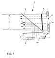
- the central axes 2a and 4a of the first display arrangement 2 and the electromechanical second display device 4 are advantageously arranged at an angle ⁇ of 90 ° to each other.
- a combination device 5 is provided at an angle of 45 ° from the electromechanical display device 4.
- this is a planar semitransparent mirror, which is permeable to the imaging light of the first display device 2, so that a viewer perceives the display image of the display device directly.
- the imaging light of the electromechanical display device 4 is reflected by the semitransparent mirror 5, so that it appears to the viewer the display image of the display device 2 as a virtual image 6 upstream.
- a diaphragm 7 made of semitransparent material is provided above the electromechanical second display device 4, which is permeable to the imaging light of the display device 4 and covers the electromechanical display device 4 for the viewer at least in the off state.
- the display image is composed by display image parts coming from the first display device 2 and from the electromechanical second display device 4.
- a display image is completely formed by a display image of the display device 2 or the display device 4.
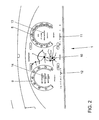
- FIG. 2 the representation of the round instruments 8, 9 for the driving speed and the engine speed by the imaging light of the electromechanical second display device 4.
- the other display elements 10-12, including the alphanumeric displays 13, 14 are derived from the first display device 2.
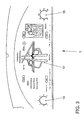
- the display image of FIG. 3 are the round instruments 8, 9 of the electromechanical display device 4 off FIG. 2 hidden or the round instruments 8, 9 are not lit or self-luminous.
- the main portion of the display image of the display device 1 faces the display image 17 of the display device 2 Available.
Landscapes
- Engineering & Computer Science (AREA)
- Radar, Positioning & Navigation (AREA)
- Remote Sensing (AREA)
- Physics & Mathematics (AREA)
- Automation & Control Theory (AREA)
- General Physics & Mathematics (AREA)
- Optics & Photonics (AREA)
- Mechanical Engineering (AREA)
- Chemical & Material Sciences (AREA)
- Transportation (AREA)
- Combustion & Propulsion (AREA)
- Multimedia (AREA)
- Instrument Panels (AREA)
- Details Of Measuring Devices (AREA)
- Lighting Device Outwards From Vehicle And Optical Signal (AREA)
- Indicating Measured Values (AREA)
- Devices For Indicating Variable Information By Combining Individual Elements (AREA)
- Illuminated Signs And Luminous Advertising (AREA)
Description
- Die Erfindung betrifft eine Anzeigeeinrichtung für ein Kraftfahrzeug, insbesondere ein Kombiinstrument, mit mindestens einer ersten freiprogrammierbaren Displayeinrichtung, welche abbildendes Licht abgibt, und mindestens einer beleuchteten oder selbstleuchtenden elektromechanischen zweiten Anzeigeeinrichtung, insbesondere mindestens ein Zeigerinstrumen (siehe z. B.
WO 99/22960 A1 - Die Anzahl von Informationen, die einem Fahrzeugführer auf Grund der steigenden Anzahl von Komforteinrichtungen, wie Navigationseinrichtungen, Telekommunikationseinrichtungen, Fahrerassistenzsystemen und gewünschter Warnhinweise etc. angezeigt werden, steigt ständig. In vielen Fahrzeugen werden deshalb schon sogenannte Multifunktions-Bedieneinrichtungen eingesetzt, die beispielsweise in der Mittelkonsole angeordnet sind. Der Fahrer ist bei dieser Anordnung für den Informationserhalt gezwungen, seinen Blick vom Fahrgeschehen abzuwenden. Aus diesem Grund ist es von Vorteil, wenigstens ein Teil der Informationen in dem in Fahrtrichtung im Blickfeld des Fahrzeugführers befindlichen Kombiinstrument anzuzeigen. Hier entsteht das Problem, dass nur eine bestimmt Anzeigefläche im Kombiinstrument neben den analogen Anzeigeelementen für Geschwindigkeit; Drehzahl etc. zur Verfügung steht.
- Aus diesem Grund wird an neuen Konzepten für Kombiinstrumente gearbeitet, die eine größere Anzahl von Informationen wiedergeben können, ohne auf die herkömmliche analogen Anzeigeinstrumente zu verzichten.
- So ist aus der europäischen Patentschrift
EP 482 805 B1 - Die abbildende Beleuchtung der zweiten Bildquelle wird dabei von der Kombiniervorrichtung durchgelassen und dann ebenfalls von den beiden Spiegeln zum Beobachter reflektiert. Dabei kann die erste Bildquelle eine Gruppe von elektromechanischen Anzeigevorrichtungen, beispielsweise von Geschwindigkeit, Öldruck, Tankniveau, und beispielsweise Anzeigetafellichter, wie Fahrtrichtungsanzeiger, Fernlicht und Notfallanzeigen, aufweisen. Die zweite Bildquelle ist eine Flüssigkeitskristallanzeige, um alphanumerische Informationen, wie Nachrichten, Wartungsanweisungen und Einstellungen für die Umgebung, bereitzustellen. Bei der bekannten Anzeigeeinrichtung befindet sich keine der beiden Bildquellen im direkten Blickfeld des Fahrzeugführers, so dass ein rein virtuelles Bild entsteht. Des Weiteren ist es schwierig, die durch die unterschiedlich angeordneten Bildquellen und die mehrfachen Reflexionen des abbildenden Lichtes der Bildquellen entstehenden Parallaxen dahingehend in den Griff zu bekommen, dass keine Bildverzerrungen entstehen.
- Im weiteren offenbart die japanische Patentanmeldung
JP 2002079848 A - Aus der o.g.
WO 99/22960 A1 - Es ist die Aufgabe der Erfindung, eine Anzeigeeinrichtung für ein Kraftfahrzeug zu schaffen, mit deren Hilfe eine größere Menge von Informationen in unterschiedlichen Anzeigemodi übersichtlich dargestellt werden kann.
- Die Aufgabe wird durch die Merkmale des Patentanspruchs 1 gelöst. Vorteilhafte Ausuns Weiterbildungen sind im Unteranspruch dargestellt.
- Gemäß der Erfindung ist die erste freiprogrammierbare Displayeinrichtung, die eine Flüssigkeitskristallanzeige, eine OLED-Anzeige oder irgendeine andere Anzeigeeinrichtung dieser Art sein kann, im Blickfeld des Betrachters angeordnet. Eine zweite elektromechanische Anzeigeeinrichtung, die Anzeigeelemente eines herkömmlichen Kombiinstrumentes, wie Rundinstrumente zur Geschwindigkeitsanzeige, aufweist, ist in einem Winkel zu der ersten Displayeinrichtung außerhalb des Blickfeldes des Fahrzeugführers, während er das Fahrzeug führt, angeordnet. Zwischen der ersten Displayeinrichtung und der elektromechanischen zweiten Anzeigeeinrichtung ist eine Kombinationseinrichtung derart angeordnet, dass sie das abbildende Licht der ersten Displayeinrichtung und der elektromechanischen zweiten Anzeigeeinrichtung zu einem gemeinsamen Anzeigebild zusammenführt, wobei die Kombinationseinrichtung für das abbildende Licht der ersten Displayeinrichtung durchlässig ausgebildet ist und weiterhin derart ausgebildet ist, dass sie das abbildende Licht der elektromechanischen zweiten Anzeigeeinrichtung reflektiert.
- In mindestens einem Anzeigemodus der Anzeigeeinrichtung bildet das abbildende Licht der elektromechanischen zweiten Anzeigeeinrichtung durch die Beleuchtung oder die selbstleuchtende Ansteuerung mindestens eines Rundinstrumentes mindestens ein Rundinstrument, vorzugsweise mit mindestens einer Zeigerdarstellung. Wird der Zeiger nur teilweise im Bereich der Rundskala des Rundinstrumentes beleuchtet oder selbstleuchtend angesteuert, kann der Flächeninhalt des durch das abbildende Licht gebildeten Rundinstrumentes im Anzeigebild der Anzeigeeinrichtung durch das Anzeigebild der ersten Displayeinrichtung zur Informationsdarstellung genutzt werden.
- Die zweite elektromechanische Anzeigeeinrichtung ist unterhalb des Blickfeldes angeordnet.
- Nach einer vorteilhaften Ausbildung der erfindungsgemäßen Anzeigeeinrichtung ist diese derart aufgebaut, dass die Summe der Reflexionen des abbildenden Lichtes der ersten Displayeinrichtung und der elektromechanischen zweiten Anzeigeeinrichtung maximal vier, vorzugsweise maximal zwei, beträgt, wodurch das Problem der Bildverzerrung minimiert wird. Nach einer weiteren Ausbildung der Erfindung wird der Winkel zwischen der ersten Displayeinrichtung und der elektromechanischen zweiten Anzeigeeinrichtung durch jeweils eine Mittelachse der ersten Displayeinrichtung und der zweiten elektromechanischen Anzeigeeinrichtung gebildet.
- Vorzugsweise ist zumindest die anzeigewirksame Fläche der elektromechanischen zweiten Anzeigeeinrichtung gemeinsam mit der Kombinationseinrichtung beabstandet zur Anzeigefläche der ersten Displayeinrichtung angeordnet, so dass das Anzeigebild der elektromechanischen Anzeigeeinrichtung, unabhängig ob sie vollständig oder teilweise abbildendes Licht abgibt, virtuell in einem Abstand vor der Anzeigefläche der Displayeinrichtung projiziert wird, so dass virtuell zumindest teilweise ein dreidimensionales Bild erzeugt wird. Über die Größe des Abstandes der Kombinationseinrichtung und der anzeigewirksamen Fläche der elektromechanischen Anzeigeeinrichtung wird der Abstand, in dem das Anzeigebild der elektromechanischen Anzeigeeinrichtung der Anzeige der ersten Displayeinrichtung virtuell vorgelagert ist, bestimmt.
- Der Winkel zwischen der ersten Displayeinrichtung und der elektromechanischen zweiten Anzeigeeinrichtung ist kleiner als 180° und liegt vorzugsweise im Bereich zwischen 75° und 120°. Besonders vorteilhaft hat sich ein Winkel von 90° herausgestellt.
- Zur Minimierung von Verzerrungen ist vorgesehen, dass die Kombinationseinrichtung den Winkel zwischen der ersten Displayanordnung und der elektromechanischen zweiten Anzeigeeinrichtung im Wesentlichen halbiert. Bei einem Winkel von 90° zwischen den beiden Anzeigeeinrichtungen ist diese in einem Winkel von 45° zu beiden Anzeigeeinrichtungen angeordnet.
- Gemäß einer bevorzugten Ausführung der Erfindung ist die Kombinationseinrichtung ein teil- oder semitransparenter Spiegel, der für das Anzeigebild der ersten Displayeinrichtung durchlässig und für das Anzeigebild der elektromechanischen zweiten Anzeigeeinrichtung reflektierend ausgebildet ist.
- Des Weiteren kann vorgesehen sein, dass das Anzeigebild der Anzeigeeinrichtung in mindestens in einem Anzeigemodus durch die Überlagerung des Anzeigebildes der ersten Displayeinrichtung und durch das reflektierte abbildende Licht der elektromechanischen Anzeigevorrichtung gebildet wird.
- Gemäß einer vorteilhaften Ausbildung der Erfindung sind in mindestens einem Anzeigemodus nur ein oder mehrere Teile der elektromechanischen zweiten Anzeigeeinrichtung beleuchtbar und/oder selbstleuchtend angesteuert.
- Neben dem mindestens einem Rundinstrument kann die elektromechanische zweite Anzeigeeinrichtung zusätzlich steuerbare Warnanzeigen, insbesondere Leuchtflächenanzeigen, beispielsweise für Blinker, Fernlicht, und/oder Warnleuchten, aufweisen.
- In einer Ausbildung der Erfindung weist die elektromechanische zweite Anzeigeeinrichtung zumindest eine erste Messgrößenanzeige, insbesondere eine Geschwindigkeitsanzeige, vorzugsweise ein Rundinstrument, auf, die in einem Hauptbereich der elektromechanischen zweiten Anzeigeeinrichtung angeordnet ist. Des Weiteren ist in der elektromechanischen Anzeigeeinrichtung mindestens eine zweite Anzeige der gleichen Messgröße, insbesondere eine Geschwindigkeitsanzeige, vorzugsweise ebenfalls ein Rundinstrument, vorgesehen, die in einem seitlichen Bereich der elektromechanischen Anzeigeeinrichtung angeordnet ist. In mindestens einem Anzeigemodus der erfindungsgemäßen Anzeigeeinrichtung wird die erste Messgrößenanzeige und in mindestens einem weiteren Anzeigemodus die zweite Messgrößenanzeige dargestellt.
- Vorzugsweise ist die zweite Messgrößenanzeige kleiner als die erste Messgrößenanzeige, vorzugsweise weist sie maximal ¾ der Größe, insbesondere jedoch maximal ½ der Größe, der ersten Messgrößenanzeige auf. Dies hat den Vorteil, dass in den Anzeigemodi, in denen das Anzeigebild der zweiten Messgrößenanzeige zur Anzeige kommt, der größte Teil des Anzeigebildes der Anzeigeeinrichtung für das Anzeigebild der ersten Displayeinrichtung genutzt werden kann.
- In dem mindestens einem Anzeigemodus, in dem das Anzeigebild der zweiten Messgrößenanzeige zur Anzeige kommt, wird im Bereich der ersten Messgrößenanzeige im Wesentlichen nur das Anzeigebild der ersten Displayeinrichtung dargestellt. Ähnliche Messgrößenanzeigen können auch für andere Messgrößen, wie beispielsweise für die Motordrehzahl des Fahrzeuges, realisiert sein.
- Nach einer vorteilhaften Ausbildung der Erfindung ist die erfindungsgemäße Anzeigeeinrichtung als so genanntes Kombinationsinstrument ausgebildet, das in Blickrichtung des Fahrers im Kraftfahrzeug angeordnet ist.
- Nachfolgend wird die Erfindung anhand eines Ausführungsbeispiels näher beschrieben. Die zugehörigen Zeichnungen zeigen:
- Figur 1:
- einen schematischen Aufbau der erfindungsgemäßen Anzeigeeinrichtung,
- Figur 2:
- ein Anzeigebild der erfindungsgemäßen Anzeigeeinrichtung und
- Figur 3:
- ein weiteres Anzeigebild der erfindungsgemäßen Anzeigeeinrichtung.
- Die in
Figur 1 gezeigte Anzeigeeinrichtung 1 für ein Kombiinstrument eines Kraftfahrzeugs besteht im Wesentlichen aus einer ersten Displayeinrichtung 2, die sich im unmittelbaren Blickfeld 3 des Fahrzeugführers im Bereich eines nicht dargestellten Lenkrades befindet, wenn dieser das Kraftfahrzeug führt, und einer elektromechanischen zweiten Anzeigeeinrichtung 4, die im Ausführungsbeispiel liegend, unterhalb des Blickfeldes 3 des Fahrzeugführers angeordnet ist. Die elektromechanische zweite Anzeigeeinrichtung 4 kann dabei wie ein herkömmliches Kombiinstrument mit mehreren Rundinstrumenten aufgebaut sein, deren Skalen selbstleuchtend oder beleuchtend ausgeführt sind und einen beleuchteten oder selbstleuchtenden Zeiger zur Kenntlichmachung des aktuellen Wertes aufweisen. Des Weiteren kann die elektromechanische Anzeigeeinrichtung ein oder mehrere Leuchtflächenanzeigen für Warnanzeigen oder Warnleuchten aufweisen. - Die Mittelachsen 2a und 4a der ersten Displayanordnung 2 und der elektromechanischen zweiten Anzeigeeinrichtung 4 sind vorteilhafterweise in einem Winkel α von 90° zueinander angeordnet. In einem Winkel von 45° von der elektromechanischen Anzeigeeinrichtung 4 ist eine Kombinationseinrichtung 5 vorgesehen. Im Ausführungsbeispiel ist dies ein planarer semitransparenter Spiegel, der für das abbildende Licht der ersten Displayeinrichtung 2 durchlässig ausgebildet ist, so dass ein Betrachter das Anzeigebild der Displayeinrichtung direkt wahrnimmt. Das abbildende Licht der elektromechanischen Anzeigeeinrichtung 4 wird von dem semitransparenten Spiegel 5 reflektiert, so dass es für den Betrachter dem Anzeigebild der Displayeinrichtung 2 als virtuelles Bild 6 vorgelagert erscheint. Im Ausführungsbeispiel ist oberhalb der elektromechanischen zweiten Anzeigeeinrichtung 4 eine Blende 7 aus semitransparenten Material vorgesehen, die für das abbildende Licht der Anzeigeeinrichtung 4 durchlässig ausgebildet ist und die elektromechanische Anzeigeeinrichtung 4 für den Betrachter zumindest im ausgeschalteten Zustand abdeckt.
- In den
Figuren 2 und3 sind mögliche Anzeigebilder der erfindungsgemäßen Anzeigeeinrichtung 1 dargestellt. - In beiden Figuren setzt sich das Anzeigebild durch Anzeigebildteile, die von der ersten Displayeinrichtung 2 und von der elektromechanischen zweiten Anzeigeeinrichtung 4 kommen, zusammen. Es ist jedoch auch möglich, dass ein Anzeigebild vollständig durch ein Anzeigebild der Displayeinrichtung 2 oder der Anzeigeeinrichtung 4 gebildet ist. In
Figur 2 erfolgt die Darstellung der Rundinstrumente 8, 9 für die Fahrgeschwindigkeit und die Motordrehzahl durch das abbildende Licht der elektromechanischen zweiten Anzeigeeinrichtung 4. Die anderen Anzeigeelemente 10 - 12, einschließlich der alphanumerischen Anzeigen 13, 14 stammen von der ersten Displayeinrichtung 2. Bei dem Anzeigebild derFigur 3 sind die Rundinstrumente 8, 9 der elektromechanischen Anzeigeeinrichtung 4 ausFigur 2 ausgeblendet bzw. die Rundinstrumente 8, 9 sind nicht beleuchtet oder selbstleuchtend angesteuert. Damit steht der Hauptbereich des Anzeigebildes der Anzeigeeinrichtung 1 dem Anzeigebild 17 der Displayeinrichtung 2 zur Verfügung. Für die Anzeige der Fahrgeschwindigkeit und der Motordrehzahl sind im Randbereich der elektromechanischen zweiten Anzeigeeinrichtung 4 kleinere Rundinstrumente 15, 16 beleuchtet bzw. selbstleuchtend angesteuert, so dass diese Rundinstrumente 15, 16 im Anzeigebild der Anzeigeeinrichtung 1 dem Anzeigebild 17 der Displayeinrichtung 2 vorgelagert sind. Die Anzeigebilder derFigur 2 undFigur 3 sind hier nur beispielhaft angegeben. Im Rahmen der Erfindung ist die Realisierung der unterschiedlichsten Anzeigebilder der Anzeigeeinrichtung 1 mit den gleichen als auch anderen Anzeigeelementen denkbar.
Claims (2)
- Anzeigeeinrichtung für ein Kraftfahrzeug, insbesondere ein Kombiinstrument, mit mindestens einer ersten Displayeinrichtung (2), welche abbildendes Licht abgibt, und mindestens einer beleuchteten und/oder selbstleuchtenden elektromechanischen zweiten Anzeigeeinrichtung (4), insbesondere mindestens ein Zeigerinstrument, mit folgenden Merkmalen:- die erste Displayeinrichtung (2) ist in einem Blickfeld (3) eines Betrachters angeordnet,- die erste Displayeinrichtung (2) und die zweite elektromechanische Anzeigeeinrichtung (4) sind in einem Winkel (α) zueinander angeordnet,- zwischen der ersten Displayeinrichtung (2) und der elektromechanischen zweiten Anzeigeeinrichtung (4) ist eine Kombinationseinrichtung (5) vorgesehen, die für das abbildende Licht der ersten Displayeinrichtung (2) durchlässig und für das abbildende Licht der elektromechanischen zweiten Anzeigeeinrichtung (4) reflektierend ausgebildet ist,gekennzeichnet durch die weiteren Merkmale:- in mindestens einem Anzeigemodus bildet das abbildende Licht der elektromechanischen zweiten Anzeigeinrichtung (4) mindestens ein Rundinstrument (8, 9, 15, 16),- die zweite elektromechanische Anzeigeeinrichtung (4) ist unterhalb des Blickfeldes (3) des Betrachters angeordnet.
- Anzeigeeinrichtung nach Anspruch 1, dadurch gekennzeichnet, dass oberhalb der elektromechanischen zweiten Anzeigeeinrichtung (4) eine Blende (7) aus semitransparentem Material vorgesehen ist, die für das abbildende Licht der elektromechanischen zweiten Anzeigeeinrichtung (4) durchlässig ausgebildet ist und die elektromechanische zweite Anzeigeeinrichtung (4) für den Betrachter zumindest im ausgeschalteten Zustand abdeckt.
Priority Applications (2)
| Application Number | Priority Date | Filing Date | Title |
|---|---|---|---|
| EP07010589A EP1818206A3 (de) | 2003-07-23 | 2004-06-08 | Anzeigeeinrichtung für ein Kraftfahrzeug |
| DE202004021362U DE202004021362U1 (de) | 2003-07-23 | 2004-06-08 | Anzeigeeinrichtung für ein Kraftfahrzeug |
Applications Claiming Priority (2)
| Application Number | Priority Date | Filing Date | Title |
|---|---|---|---|
| DE10333745A DE10333745A1 (de) | 2003-07-23 | 2003-07-23 | Anzeigeeinrichtung für ein Kraftfahrzeug |
| PCT/EP2004/006156 WO2005018976A1 (de) | 2003-07-23 | 2004-06-08 | Anzeigeeinrichtung für ein kraftfahrzeug |
Related Child Applications (2)
| Application Number | Title | Priority Date | Filing Date |
|---|---|---|---|
| EP07010589A Division EP1818206A3 (de) | 2003-07-23 | 2004-06-08 | Anzeigeeinrichtung für ein Kraftfahrzeug |
| EP07010589.5 Division-Into | 2007-05-29 |
Publications (2)
| Publication Number | Publication Date |
|---|---|
| EP1651463A1 EP1651463A1 (de) | 2006-05-03 |
| EP1651463B1 true EP1651463B1 (de) | 2010-08-18 |
Family
ID=34201379
Family Applications (2)
| Application Number | Title | Priority Date | Filing Date |
|---|---|---|---|
| EP07010589A Ceased EP1818206A3 (de) | 2003-07-23 | 2004-06-08 | Anzeigeeinrichtung für ein Kraftfahrzeug |
| EP04739685A Expired - Lifetime EP1651463B1 (de) | 2003-07-23 | 2004-06-08 | Anzeigeeinrichtung für ein kraftfahrzeug |
Family Applications Before (1)
| Application Number | Title | Priority Date | Filing Date |
|---|---|---|---|
| EP07010589A Ceased EP1818206A3 (de) | 2003-07-23 | 2004-06-08 | Anzeigeeinrichtung für ein Kraftfahrzeug |
Country Status (7)
| Country | Link |
|---|---|
| US (1) | US7669543B2 (de) |
| EP (2) | EP1818206A3 (de) |
| JP (1) | JP2006528101A (de) |
| CN (1) | CN100421984C (de) |
| AT (1) | ATE477956T1 (de) |
| DE (2) | DE10333745A1 (de) |
| WO (1) | WO2005018976A1 (de) |
Families Citing this family (54)
| Publication number | Priority date | Publication date | Assignee | Title |
|---|---|---|---|---|
| FR2867112B1 (fr) * | 2004-03-03 | 2006-05-12 | Johnson Controls Tech Co | Combine de vehicule automobile a renvoi d'image |
| DE102004054771B4 (de) | 2004-11-12 | 2017-05-24 | Volkswagen Ag | Einbau-Kombinationsinstrument für ein Kraftfahrzeug |
| JP4577500B2 (ja) * | 2004-11-29 | 2010-11-10 | 日本精機株式会社 | 表示装置 |
| DE102005017313A1 (de) | 2005-04-14 | 2006-10-19 | Volkswagen Ag | Verfahren zur Darstellung von Informationen in einem Verkehrsmittel und Kombiinstrument für ein Kraftfahrzeug |
| DE102005029800A1 (de) * | 2005-06-27 | 2007-01-04 | Volkswagen Ag | Kombiinstrument für ein Kraftfahrzeug |
| DE102005034096A1 (de) * | 2005-07-21 | 2007-01-25 | Volkswagen Ag | Kombiinstrument für ein Kraftfahrzeug |
| DE102006032118B4 (de) | 2006-07-12 | 2022-03-03 | Volkswagen Ag | Kombiinstrument für ein Kraftfahrzeug und Kraftfahrzeug |
| FR2909598B1 (fr) * | 2006-12-06 | 2009-07-31 | Peugeot Citroen Automobiles Sa | Combine d'instrumentation a effet de profondeur |
| DE102007041742B4 (de) * | 2007-01-18 | 2010-10-07 | Johnson Controls Gmbh | Anzeigeinstrument und Verfahren zum Betrieb eines Anzeigeinstruments |
| DE102007014531B4 (de) * | 2007-03-27 | 2022-03-31 | Volkswagen Ag | Verfahren und Vorrichtung zum Anzeigen von Informationen in einem Fahrzeug |
| DE102008016527B4 (de) | 2007-04-03 | 2018-12-13 | Denso Corporation | Fahrzeug-Messgeräte-Einheit und Anzeigevorrichtung |
| JP2008254703A (ja) * | 2007-04-09 | 2008-10-23 | Denso Corp | 車両用メーターユニット |
| DE102007018073A1 (de) * | 2007-04-17 | 2008-10-23 | Volkswagen Ag | Verfahren zum Anzeigen einer digitalen Karte in einem Fahrzeug und Anzeigeeinrichtung hierfür |
| DE102007018072A1 (de) * | 2007-04-17 | 2008-10-30 | Volkswagen Ag | Anzeigeeinrichtung für ein Fahrzeug zum Anzeigen von den Betrieb des Fahrzeugs betreffende Informationen und Verfahren zum Anzeigen dieser Informationen |
| DE102008023839A1 (de) * | 2008-05-16 | 2009-11-26 | Continental Automotive Gmbh | Anzeigeeinrichtung |
| JP5142042B2 (ja) * | 2008-06-26 | 2013-02-13 | 日本精機株式会社 | 車両用表示装置 |
| DE102008051385A1 (de) * | 2008-10-11 | 2010-04-15 | Man Nutzfahrzeuge Aktiengesellschaft | Optisches Anzeigesystem |
| US7954965B1 (en) * | 2009-04-13 | 2011-06-07 | Yazaki North America, Inc. | Method for multiple gauges in a scanning laser based display device |
| US8026827B1 (en) | 2009-05-04 | 2011-09-27 | Yazaki North America, Inc. | Virtual push button switch |
| KR101695809B1 (ko) * | 2009-10-09 | 2017-01-13 | 엘지전자 주식회사 | 이동 단말기 및 그 제어방법 |
| DE102009058145A1 (de) * | 2009-12-12 | 2011-06-16 | Volkswagen Ag | Bedienverfahren für eine Anzeigevorrichtung eines Fahrzeugs |
| CN103507639B (zh) * | 2012-06-27 | 2016-06-01 | 比亚迪股份有限公司 | 一种车载显示设备及具有该设备的车辆 |
| GB2504311A (en) * | 2012-07-25 | 2014-01-29 | Bae Systems Plc | Head-up display using fluidic lens |
| US9316828B2 (en) | 2012-08-22 | 2016-04-19 | Honda Motor Co., Ltd. | Three-dimensional vehicle backup camera display system and method |
| US20140282182A1 (en) * | 2013-03-15 | 2014-09-18 | Honda Moror Co., Ltd. | Multi-layered vehicle display system and method |
| US9291819B2 (en) | 2013-09-05 | 2016-03-22 | Texas Instruments Incorporated | Multi-focus heads-up display using single picture generator unit |
| WO2015037045A1 (ja) | 2013-09-10 | 2015-03-19 | 三菱電機株式会社 | 情報処理装置、情報表示装置および表示制御方法 |
| DE102013220994A1 (de) * | 2013-10-16 | 2015-04-16 | Volkswagen Aktiengesellschaft | Verfahren und Vorrichtung zur Einstellung von Komfortparametern sowie Kraftfahrzeug |
| JP6073497B2 (ja) * | 2013-11-12 | 2017-02-01 | 三菱電機株式会社 | 表示制御装置、情報表示方法および情報表示システム |
| US9914360B2 (en) * | 2014-03-25 | 2018-03-13 | Daniel Isaac Becker | Gearshift optimization gauge |
| JP6540988B2 (ja) * | 2014-06-09 | 2019-07-10 | 日本精機株式会社 | ヘッドアップディスプレイ装置 |
| CN107206901B (zh) * | 2015-02-20 | 2019-06-14 | Jvc 建伍株式会社 | 车辆用显示装置 |
| CN104960422A (zh) * | 2015-06-19 | 2015-10-07 | 延锋伟世通电子科技(上海)有限公司 | 汽车仪表3d显示结构 |
| FR3041786B1 (fr) * | 2015-09-29 | 2018-02-16 | Peugeot Citroen Automobiles Sa | Dispositif d'affichage de vehicule |
| JP6467386B2 (ja) | 2016-09-14 | 2019-02-13 | 矢崎総業株式会社 | 車両用表示装置 |
| CN106441415B (zh) * | 2016-09-22 | 2019-07-09 | 江铃汽车股份有限公司 | 一种车辆仪表视差的校核方法 |
| FR3057511B1 (fr) * | 2016-10-13 | 2021-05-14 | Peugeot Citroen Automobiles Sa | Rangement de vehicule avec masque |
| DE102017102041A1 (de) * | 2017-02-02 | 2018-08-02 | Visteon Global Technologies, Inc. | Anzeigevorrichtung |
| FR3069088B1 (fr) * | 2017-07-11 | 2019-08-16 | Faurecia Interieur Industrie | Dispositif d'affichage et habillage interieur de vehicule comprenant un tel dispositif d'affichage |
| KR102015497B1 (ko) * | 2017-10-26 | 2019-08-28 | 엘지전자 주식회사 | 디스플레이 장치 및 그것을 포함하는 차량 |
| US10310323B1 (en) * | 2018-02-12 | 2019-06-04 | Visteon Global Technologies, Inc. | Bright panel display cluster |
| FR3093962A1 (fr) | 2019-03-21 | 2020-09-25 | Psa Automobiles Sa | Dispositif d’affichage à lame semi-réfléchissante montée à rotation, pour une planche de bord de véhicule |
| FR3098607A1 (fr) | 2019-07-09 | 2021-01-15 | Psa Automobiles Sa | Dispositif d’affichage pour véhicule |
| DE102019211518B3 (de) * | 2019-08-01 | 2020-08-20 | Audi Ag | Anzeigevorrichtung für ein Kraftfahrzeug und Kraftfahrzeug mit einer Anzeigevorrichtung |
| FR3101818B1 (fr) | 2019-10-10 | 2022-04-15 | Psa Automobiles Sa | Dispositif d’affichage pour véhicule automobile. |
| FR3101964B1 (fr) | 2019-10-10 | 2022-03-18 | Psa Automobiles Sa | Procédé de conversion d’une image 2D pour obtenir un effet 3D sur un combiné d’instrument automobile |
| FR3101819B1 (fr) | 2019-10-10 | 2022-03-18 | Psa Automobiles Sa | Procédé de valorisation d’une information sur un combiné d’instrument automobile. |
| FR3118203B1 (fr) | 2020-12-21 | 2022-11-04 | Psa Automobiles Sa | Dispositif d’affichage pour véhicule avec image virtuelle paramétrable |
| CN113858948B (zh) * | 2021-08-17 | 2023-02-03 | 黑龙江天有为电子有限责任公司 | 一种裸眼3d汽车仪表盘及汽车 |
| CN113752831B (zh) * | 2021-08-17 | 2023-06-20 | 黑龙江天有为电子有限责任公司 | 一种汽车仪表盘 |
| CN113771621B (zh) * | 2021-09-15 | 2022-09-27 | 黑龙江天有为电子有限责任公司 | 一种立体式组合仪表盘 |
| CN113895228B (zh) * | 2021-10-11 | 2022-05-17 | 黑龙江天有为电子有限责任公司 | 一种汽车组合仪表盘及汽车 |
| CN113954635A (zh) * | 2021-10-27 | 2022-01-21 | 黑龙江天有为电子有限责任公司 | 一种汽车仪表信息的显示方法 |
| CN116101057A (zh) * | 2021-11-10 | 2023-05-12 | 黑龙江天有为电子有限责任公司 | 一种组合汽车仪表中显示图案的动态显示方法 |
Family Cites Families (33)
| Publication number | Priority date | Publication date | Assignee | Title |
|---|---|---|---|---|
| DE1623738A1 (de) | 1967-06-19 | 1971-01-28 | Gabor Jakab | Integriertes Anzeigegeraet auf optischer Basis fuer Kraftfahrzeuge,hauptsaechlich fuer Personenwagen,zum Anzeigen der Fahrparameter sowie der Kontrolldaten des Antriebmotors |
| JPS59176767A (ja) * | 1983-03-25 | 1984-10-06 | 株式会社デンソー | 車両用表示装置 |
| JPH075036B2 (ja) | 1987-03-19 | 1995-01-25 | 日本電装株式会社 | 車両用表示装置 |
| US5278532A (en) | 1987-09-14 | 1994-01-11 | Hughes Aircraft Company | Automotive instrument virtual image display |
| JPH03273942A (ja) * | 1990-03-22 | 1991-12-05 | Nippon Seiki Co Ltd | 車両用表示装置 |
| GB2244569A (en) | 1990-06-01 | 1991-12-04 | Delco Electronics Corp | Image source for head-up display |
| JP2546188Y2 (ja) | 1990-08-07 | 1997-08-27 | 矢崎総業株式会社 | 車両用表示装置 |
| JP2922604B2 (ja) | 1990-08-24 | 1999-07-26 | 矢崎総業株式会社 | 車両用表示装置 |
| US5121099A (en) * | 1990-08-31 | 1992-06-09 | Hughes Aircraft Company | Two-page automotive virtual image display |
| JP3125811B2 (ja) | 1991-08-22 | 2001-01-22 | 株式会社デンソー | 倒立型交差コイル式ムーブメント |
| JPH06262965A (ja) * | 1993-03-10 | 1994-09-20 | Yazaki Corp | 虚像式メータ |
| DE4323082C2 (de) * | 1993-07-10 | 1997-12-04 | Mannesmann Vdo Ag | Anzeigeeinheit für Kraftfahrzeuge |
| DE4407855B4 (de) | 1994-01-29 | 2006-03-16 | Siemens Ag | Anzeigeeinheit |
| DE9403940U1 (de) | 1994-01-29 | 1994-05-05 | Vdo Adolf Schindling Ag, 60487 Frankfurt | Anzeigeeinheit |
| US5576886A (en) | 1994-08-08 | 1996-11-19 | Mcdonnell Douglas Corp. | Hud with a spectral contour dielectric combiner |
| DE4434443C2 (de) | 1994-09-27 | 2001-09-13 | Daimler Chrysler Ag | Optisches Mehrfachanzeigeinstrument, insbesondere für eine Instrumententafel eines Fahrzeugs |
| FR2727559A1 (fr) | 1994-11-25 | 1996-05-31 | Magneti Marelli France | Dispositif d'affichage pour vehicule automobile |
| JPH08175227A (ja) * | 1994-12-21 | 1996-07-09 | Kansei Corp | 表示装置 |
| JPH09254680A (ja) * | 1996-03-22 | 1997-09-30 | Yazaki Corp | 虚像表示式メータ |
| US6278532B1 (en) * | 1996-12-20 | 2001-08-21 | Link2It | Apparatus and method for reception and transmission of information using different protocols |
| JP2001506772A (ja) * | 1996-12-20 | 2001-05-22 | シーメンス アクチエンゲゼルシヤフト | 少なくとも一人のための情報表示システム |
| FR2758405B1 (fr) | 1997-01-10 | 1999-02-12 | Renault | Dispositif et procede d'affichage d'informations sur le poste de conduite d'un vehicule routier |
| CA2306915A1 (en) * | 1997-11-03 | 1999-05-14 | Douglas Hall | Virtual instrument panel |
| JPH11170890A (ja) * | 1997-12-16 | 1999-06-29 | Denso Corp | 車両用表示装置 |
| JP3514099B2 (ja) | 1998-01-30 | 2004-03-31 | 株式会社デンソー | 複合表示装置 |
| DE19814904C2 (de) | 1998-04-02 | 2001-10-11 | Bosch Gmbh Robert | Kombiinstrument mit integrierter Displayanzeige |
| DE19903202B4 (de) | 1999-01-27 | 2007-12-13 | Siemens Ag | Anzeigevorrichtung mit Zeiger |
| IT1307694B1 (it) | 1999-05-14 | 2001-11-14 | Fiat Ricerche | Pannello strumenti per autoveicoli con sistema di visualizzazioneausiliario attivabile mediante petali elettrostatici |
| JP2001322454A (ja) * | 2000-05-15 | 2001-11-20 | Denso Corp | 車両用計器 |
| JP2001341685A (ja) * | 2000-05-30 | 2001-12-11 | Moric Co Ltd | 鞍乗型車両におけるメータ表示装置 |
| JP2002079848A (ja) | 2000-09-06 | 2002-03-19 | Denso Corp | 車両用計器及びそのフロントパネル |
| US6812942B2 (en) | 2000-12-28 | 2004-11-02 | International Business Machines Corporation | Context-responsive in-vehicle display system |
| JP2004538480A (ja) | 2001-08-15 | 2004-12-24 | シーメンス アクチエンゲゼルシヤフト | 表示器ユニット |
-
2003
- 2003-07-23 DE DE10333745A patent/DE10333745A1/de not_active Withdrawn
-
2004
- 2004-06-08 EP EP07010589A patent/EP1818206A3/de not_active Ceased
- 2004-06-08 CN CNB2004800210926A patent/CN100421984C/zh not_active Expired - Lifetime
- 2004-06-08 AT AT04739685T patent/ATE477956T1/de active
- 2004-06-08 WO PCT/EP2004/006156 patent/WO2005018976A1/de not_active Ceased
- 2004-06-08 JP JP2006520685A patent/JP2006528101A/ja active Pending
- 2004-06-08 EP EP04739685A patent/EP1651463B1/de not_active Expired - Lifetime
- 2004-06-08 US US10/565,865 patent/US7669543B2/en active Active
- 2004-06-08 DE DE502004011560T patent/DE502004011560D1/de not_active Expired - Lifetime
Also Published As
| Publication number | Publication date |
|---|---|
| ATE477956T1 (de) | 2010-09-15 |
| WO2005018976A1 (de) | 2005-03-03 |
| EP1818206A3 (de) | 2008-09-10 |
| US7669543B2 (en) | 2010-03-02 |
| EP1651463A1 (de) | 2006-05-03 |
| DE502004011560D1 (de) | 2010-09-30 |
| US20060278155A1 (en) | 2006-12-14 |
| CN1826242A (zh) | 2006-08-30 |
| JP2006528101A (ja) | 2006-12-14 |
| DE10333745A1 (de) | 2005-03-31 |
| EP1818206A2 (de) | 2007-08-15 |
| WO2005018976A8 (de) | 2005-07-28 |
| CN100421984C (zh) | 2008-10-01 |
Similar Documents
| Publication | Publication Date | Title |
|---|---|---|
| EP1651463B1 (de) | Anzeigeeinrichtung für ein kraftfahrzeug | |
| DE10212600B4 (de) | Anzeigevorrichtung für Fahrzeuge mit Lichtquellen unterschiedlicher Richtschärfe | |
| DE102014219371B4 (de) | Kraftfahrzeug mit einer Beleuchtungseinrichtung | |
| DE10026136B4 (de) | Transparente elektrolumineszierende Anzeige mit mechanischem Messer | |
| DE102015225343B4 (de) | Fortbewegungsmittel und Anordnung für ein Fortbewegungsmittel zur Ausgabe richtungsanaloger Hinweise auf Umgebungsdetails | |
| DE2857738C2 (de) | Armaturenanordnung für Kraftfahrzeuge | |
| DE112011102929T5 (de) | Fahrzeug-Anzeigevorrichtung und Fahrzeug-Anzeigesystem | |
| WO2013189808A1 (de) | Head-up-display für kraftfahrzeuge zur bilddarstellung in mehreren bildebenen | |
| DE102008000606A1 (de) | Fahrzeuganzeigeinstrumentsystem und Verfahren, dieses zu steuern | |
| DE102016209086B4 (de) | Anzeigevorrichtung | |
| DE102018217989A1 (de) | Fahrzeuginterne Fotografiervorrichtung | |
| DE102017216050A1 (de) | Fahrzeuganzeigeeinrichtung | |
| DE102017202490B4 (de) | Fahrzeuganzeigevorrichtung | |
| DE102014224311A1 (de) | Anzeigeeinrichtung mit einem Lichtleiter für eine 360°-Beleuchtung | |
| DE102004054769B4 (de) | Einbau-Kombinationsinstrument für ein Kraftfahrzeug | |
| EP1735656B1 (de) | Einbau-kombinationsinstrument | |
| DE102016123257B3 (de) | Anzeigeeinrichtung für ein Kraftfahrzeug | |
| DE102008052420A1 (de) | Anzeigevorrichtung für ein Fahrzeug | |
| DE102008032061B4 (de) | Anzeigevorrichtung für den Innenraum eines Fahrzeugs | |
| DE102023100331B3 (de) | Anzeigesystem und Verfahren zum Darstellen eines Anzeigeinhalts | |
| EP2170643B1 (de) | Anzeigeeinrichtung für ein fahrzeug | |
| DE10241267A1 (de) | Lenkrad | |
| DE202004021362U1 (de) | Anzeigeeinrichtung für ein Kraftfahrzeug | |
| DE102004054771A1 (de) | Einbau-Kombinationsinstrument für ein Kraftfahrzeug | |
| DE102004052065A1 (de) | Drehzahlanzeigevorrichtung |
Legal Events
| Date | Code | Title | Description |
|---|---|---|---|
| PUAI | Public reference made under article 153(3) epc to a published international application that has entered the european phase |
Free format text: ORIGINAL CODE: 0009012 |
|
| 17P | Request for examination filed |
Effective date: 20060223 |
|
| AK | Designated contracting states |
Kind code of ref document: A1 Designated state(s): AT BE BG CH CY CZ DE DK EE ES FI FR GB GR HU IE IT LI LU MC NL PL PT RO SE SI SK TR |
|
| DAX | Request for extension of the european patent (deleted) | ||
| 17Q | First examination report despatched |
Effective date: 20061229 |
|
| RIN1 | Information on inventor provided before grant (corrected) |
Inventor name: KUHN, MATHIAS Inventor name: SOLTENDIECK, BERND Inventor name: MEDLER, ANDREAS Inventor name: HOFMANN, ROBERT Inventor name: HOFMANN, GUSTAV Inventor name: BAUER, MICHAEL |
|
| RIN1 | Information on inventor provided before grant (corrected) |
Inventor name: MEDLER, ANDREAS Inventor name: SOLTENDIECK, BERND Inventor name: HOFMANN, GUSTAV Inventor name: BAUER, MICHAEL Inventor name: HOFMANN, ROBERT Inventor name: KUHN, MATHIAS |
|
| REG | Reference to a national code |
Ref country code: DE Ref legal event code: R138 Ref document number: 202004021362 Country of ref document: DE Free format text: GERMAN DOCUMENT NUMBER IS 502004011560 |
|
| GRAP | Despatch of communication of intention to grant a patent |
Free format text: ORIGINAL CODE: EPIDOSNIGR1 |
|
| GRAJ | Information related to disapproval of communication of intention to grant by the applicant or resumption of examination proceedings by the epo deleted |
Free format text: ORIGINAL CODE: EPIDOSDIGR1 |
|
| GRAP | Despatch of communication of intention to grant a patent |
Free format text: ORIGINAL CODE: EPIDOSNIGR1 |
|
| GRAS | Grant fee paid |
Free format text: ORIGINAL CODE: EPIDOSNIGR3 |
|
| GRAA | (expected) grant |
Free format text: ORIGINAL CODE: 0009210 |
|
| AK | Designated contracting states |
Kind code of ref document: B1 Designated state(s): AT BE BG CH CY CZ DE DK EE ES FI FR GB GR HU IE IT LI LU MC NL PL PT RO SE SI SK TR |
|
| REG | Reference to a national code |
Ref country code: GB Ref legal event code: FG4D Free format text: NOT ENGLISH |
|
| REG | Reference to a national code |
Ref country code: CH Ref legal event code: EP |
|
| REG | Reference to a national code |
Ref country code: IE Ref legal event code: FG4D Free format text: LANGUAGE OF EP DOCUMENT: GERMAN |
|
| REF | Corresponds to: |
Ref document number: 502004011560 Country of ref document: DE Date of ref document: 20100930 Kind code of ref document: P |
|
| REG | Reference to a national code |
Ref country code: DE Ref legal event code: R096 Ref document number: 502004011560 Country of ref document: DE Effective date: 20100930 |
|
| REG | Reference to a national code |
Ref country code: NL Ref legal event code: VDEP Effective date: 20100818 |
|
| PG25 | Lapsed in a contracting state [announced via postgrant information from national office to epo] |
Ref country code: FI Free format text: LAPSE BECAUSE OF FAILURE TO SUBMIT A TRANSLATION OF THE DESCRIPTION OR TO PAY THE FEE WITHIN THE PRESCRIBED TIME-LIMIT Effective date: 20100818 |
|
| PG25 | Lapsed in a contracting state [announced via postgrant information from national office to epo] |
Ref country code: BG Free format text: LAPSE BECAUSE OF FAILURE TO SUBMIT A TRANSLATION OF THE DESCRIPTION OR TO PAY THE FEE WITHIN THE PRESCRIBED TIME-LIMIT Effective date: 20101118 Ref country code: SI Free format text: LAPSE BECAUSE OF FAILURE TO SUBMIT A TRANSLATION OF THE DESCRIPTION OR TO PAY THE FEE WITHIN THE PRESCRIBED TIME-LIMIT Effective date: 20100818 Ref country code: PL Free format text: LAPSE BECAUSE OF FAILURE TO SUBMIT A TRANSLATION OF THE DESCRIPTION OR TO PAY THE FEE WITHIN THE PRESCRIBED TIME-LIMIT Effective date: 20100818 Ref country code: CY Free format text: LAPSE BECAUSE OF FAILURE TO SUBMIT A TRANSLATION OF THE DESCRIPTION OR TO PAY THE FEE WITHIN THE PRESCRIBED TIME-LIMIT Effective date: 20100818 Ref country code: PT Free format text: LAPSE BECAUSE OF FAILURE TO SUBMIT A TRANSLATION OF THE DESCRIPTION OR TO PAY THE FEE WITHIN THE PRESCRIBED TIME-LIMIT Effective date: 20101220 |
|
| REG | Reference to a national code |
Ref country code: IE Ref legal event code: FD4D |
|
| PG25 | Lapsed in a contracting state [announced via postgrant information from national office to epo] |
Ref country code: NL Free format text: LAPSE BECAUSE OF FAILURE TO SUBMIT A TRANSLATION OF THE DESCRIPTION OR TO PAY THE FEE WITHIN THE PRESCRIBED TIME-LIMIT Effective date: 20100818 Ref country code: SE Free format text: LAPSE BECAUSE OF FAILURE TO SUBMIT A TRANSLATION OF THE DESCRIPTION OR TO PAY THE FEE WITHIN THE PRESCRIBED TIME-LIMIT Effective date: 20100818 Ref country code: GR Free format text: LAPSE BECAUSE OF FAILURE TO SUBMIT A TRANSLATION OF THE DESCRIPTION OR TO PAY THE FEE WITHIN THE PRESCRIBED TIME-LIMIT Effective date: 20101119 |
|
| PG25 | Lapsed in a contracting state [announced via postgrant information from national office to epo] |
Ref country code: DK Free format text: LAPSE BECAUSE OF FAILURE TO SUBMIT A TRANSLATION OF THE DESCRIPTION OR TO PAY THE FEE WITHIN THE PRESCRIBED TIME-LIMIT Effective date: 20100818 Ref country code: IE Free format text: LAPSE BECAUSE OF FAILURE TO SUBMIT A TRANSLATION OF THE DESCRIPTION OR TO PAY THE FEE WITHIN THE PRESCRIBED TIME-LIMIT Effective date: 20100818 |
|
| PG25 | Lapsed in a contracting state [announced via postgrant information from national office to epo] |
Ref country code: SK Free format text: LAPSE BECAUSE OF FAILURE TO SUBMIT A TRANSLATION OF THE DESCRIPTION OR TO PAY THE FEE WITHIN THE PRESCRIBED TIME-LIMIT Effective date: 20100818 Ref country code: RO Free format text: LAPSE BECAUSE OF FAILURE TO SUBMIT A TRANSLATION OF THE DESCRIPTION OR TO PAY THE FEE WITHIN THE PRESCRIBED TIME-LIMIT Effective date: 20100818 Ref country code: IT Free format text: LAPSE BECAUSE OF FAILURE TO SUBMIT A TRANSLATION OF THE DESCRIPTION OR TO PAY THE FEE WITHIN THE PRESCRIBED TIME-LIMIT Effective date: 20100818 Ref country code: CZ Free format text: LAPSE BECAUSE OF FAILURE TO SUBMIT A TRANSLATION OF THE DESCRIPTION OR TO PAY THE FEE WITHIN THE PRESCRIBED TIME-LIMIT Effective date: 20100818 Ref country code: EE Free format text: LAPSE BECAUSE OF FAILURE TO SUBMIT A TRANSLATION OF THE DESCRIPTION OR TO PAY THE FEE WITHIN THE PRESCRIBED TIME-LIMIT Effective date: 20100818 |
|
| PLBE | No opposition filed within time limit |
Free format text: ORIGINAL CODE: 0009261 |
|
| STAA | Information on the status of an ep patent application or granted ep patent |
Free format text: STATUS: NO OPPOSITION FILED WITHIN TIME LIMIT |
|
| PG25 | Lapsed in a contracting state [announced via postgrant information from national office to epo] |
Ref country code: ES Free format text: LAPSE BECAUSE OF FAILURE TO SUBMIT A TRANSLATION OF THE DESCRIPTION OR TO PAY THE FEE WITHIN THE PRESCRIBED TIME-LIMIT Effective date: 20101129 |
|
| 26N | No opposition filed |
Effective date: 20110519 |
|
| REG | Reference to a national code |
Ref country code: DE Ref legal event code: R097 Ref document number: 502004011560 Country of ref document: DE Effective date: 20110519 |
|
| BERE | Be: lapsed |
Owner name: VOLKSWAGEN A.G. Effective date: 20110630 |
|
| REG | Reference to a national code |
Ref country code: CH Ref legal event code: PL |
|
| GBPC | Gb: european patent ceased through non-payment of renewal fee |
Effective date: 20110608 |
|
| REG | Reference to a national code |
Ref country code: FR Ref legal event code: ST Effective date: 20120229 |
|
| PG25 | Lapsed in a contracting state [announced via postgrant information from national office to epo] |
Ref country code: BE Free format text: LAPSE BECAUSE OF NON-PAYMENT OF DUE FEES Effective date: 20110630 |
|
| PG25 | Lapsed in a contracting state [announced via postgrant information from national office to epo] |
Ref country code: CH Free format text: LAPSE BECAUSE OF NON-PAYMENT OF DUE FEES Effective date: 20110630 Ref country code: FR Free format text: LAPSE BECAUSE OF NON-PAYMENT OF DUE FEES Effective date: 20110630 Ref country code: LI Free format text: LAPSE BECAUSE OF NON-PAYMENT OF DUE FEES Effective date: 20110630 |
|
| PG25 | Lapsed in a contracting state [announced via postgrant information from national office to epo] |
Ref country code: GB Free format text: LAPSE BECAUSE OF NON-PAYMENT OF DUE FEES Effective date: 20110608 |
|
| REG | Reference to a national code |
Ref country code: AT Ref legal event code: MM01 Ref document number: 477956 Country of ref document: AT Kind code of ref document: T Effective date: 20110608 |
|
| PG25 | Lapsed in a contracting state [announced via postgrant information from national office to epo] |
Ref country code: AT Free format text: LAPSE BECAUSE OF NON-PAYMENT OF DUE FEES Effective date: 20110608 |
|
| PG25 | Lapsed in a contracting state [announced via postgrant information from national office to epo] |
Ref country code: MC Free format text: LAPSE BECAUSE OF NON-PAYMENT OF DUE FEES Effective date: 20110630 |
|
| PG25 | Lapsed in a contracting state [announced via postgrant information from national office to epo] |
Ref country code: LU Free format text: LAPSE BECAUSE OF NON-PAYMENT OF DUE FEES Effective date: 20110608 |
|
| PG25 | Lapsed in a contracting state [announced via postgrant information from national office to epo] |
Ref country code: TR Free format text: LAPSE BECAUSE OF FAILURE TO SUBMIT A TRANSLATION OF THE DESCRIPTION OR TO PAY THE FEE WITHIN THE PRESCRIBED TIME-LIMIT Effective date: 20100818 |
|
| PG25 | Lapsed in a contracting state [announced via postgrant information from national office to epo] |
Ref country code: HU Free format text: LAPSE BECAUSE OF FAILURE TO SUBMIT A TRANSLATION OF THE DESCRIPTION OR TO PAY THE FEE WITHIN THE PRESCRIBED TIME-LIMIT Effective date: 20100818 |
|
| P01 | Opt-out of the competence of the unified patent court (upc) registered |
Effective date: 20230523 |
|
| PGFP | Annual fee paid to national office [announced via postgrant information from national office to epo] |
Ref country code: DE Payment date: 20230630 Year of fee payment: 20 |
|
| REG | Reference to a national code |
Ref country code: DE Ref legal event code: R071 Ref document number: 502004011560 Country of ref document: DE |