EP1652279B1 - Verbesserungen für kabelinstallation - Google Patents
Verbesserungen für kabelinstallation Download PDFInfo
- Publication number
- EP1652279B1 EP1652279B1 EP03817972.7A EP03817972A EP1652279B1 EP 1652279 B1 EP1652279 B1 EP 1652279B1 EP 03817972 A EP03817972 A EP 03817972A EP 1652279 B1 EP1652279 B1 EP 1652279B1
- Authority
- EP
- European Patent Office
- Prior art keywords
- clip
- electrical cable
- cable
- closure member
- projection
- Prior art date
- Legal status (The legal status is an assumption and is not a legal conclusion. Google has not performed a legal analysis and makes no representation as to the accuracy of the status listed.)
- Expired - Lifetime
Links
- 238000009434 installation Methods 0.000 title claims description 15
- 238000000034 method Methods 0.000 claims description 26
- 230000009970 fire resistant effect Effects 0.000 claims description 8
- 230000007246 mechanism Effects 0.000 claims description 5
- 238000010304 firing Methods 0.000 claims 4
- 230000001419 dependent effect Effects 0.000 claims 1
- 239000000463 material Substances 0.000 description 4
- 229910000831 Steel Inorganic materials 0.000 description 3
- 230000008569 process Effects 0.000 description 3
- 239000010959 steel Substances 0.000 description 3
- 241000587161 Gomphocarpus Species 0.000 description 2
- 230000008859 change Effects 0.000 description 2
- 239000012141 concentrate Substances 0.000 description 2
- 238000010276 construction Methods 0.000 description 2
- 238000007796 conventional method Methods 0.000 description 2
- 229910001209 Low-carbon steel Inorganic materials 0.000 description 1
- 238000005452 bending Methods 0.000 description 1
- 238000005260 corrosion Methods 0.000 description 1
- 230000007797 corrosion Effects 0.000 description 1
- 238000005553 drilling Methods 0.000 description 1
- 229920003023 plastic Polymers 0.000 description 1
- 239000004033 plastic Substances 0.000 description 1
- 239000000843 powder Substances 0.000 description 1
- 238000010079 rubber tapping Methods 0.000 description 1
- 238000000926 separation method Methods 0.000 description 1
- 230000000007 visual effect Effects 0.000 description 1
Images



Classifications
-
- H—ELECTRICITY
- H02—GENERATION; CONVERSION OR DISTRIBUTION OF ELECTRIC POWER
- H02G—INSTALLATION OF ELECTRIC CABLES OR LINES, OR OF COMBINED OPTICAL AND ELECTRIC CABLES OR LINES
- H02G3/00—Installations of electric cables or lines or protective tubing therefor in or on buildings, equivalent structures or vehicles
- H02G3/30—Installations of cables or lines on walls, floors or ceilings
- H02G3/32—Installations of cables or lines on walls, floors or ceilings using mounting clamps
-
- Y—GENERAL TAGGING OF NEW TECHNOLOGICAL DEVELOPMENTS; GENERAL TAGGING OF CROSS-SECTIONAL TECHNOLOGIES SPANNING OVER SEVERAL SECTIONS OF THE IPC; TECHNICAL SUBJECTS COVERED BY FORMER USPC CROSS-REFERENCE ART COLLECTIONS [XRACs] AND DIGESTS
- Y10—TECHNICAL SUBJECTS COVERED BY FORMER USPC
- Y10T—TECHNICAL SUBJECTS COVERED BY FORMER US CLASSIFICATION
- Y10T24/00—Buckles, buttons, clasps, etc.
- Y10T24/44—Clasp, clip, support-clamp, or required component thereof
- Y10T24/44291—Clasp, clip, support-clamp, or required component thereof including pivoted gripping member
- Y10T24/4453—Clasp, clip, support-clamp, or required component thereof including pivoted gripping member with position locking-means for gripping members
- Y10T24/44538—Integral locking-means
-
- Y—GENERAL TAGGING OF NEW TECHNOLOGICAL DEVELOPMENTS; GENERAL TAGGING OF CROSS-SECTIONAL TECHNOLOGIES SPANNING OVER SEVERAL SECTIONS OF THE IPC; TECHNICAL SUBJECTS COVERED BY FORMER USPC CROSS-REFERENCE ART COLLECTIONS [XRACs] AND DIGESTS
- Y10—TECHNICAL SUBJECTS COVERED BY FORMER USPC
- Y10T—TECHNICAL SUBJECTS COVERED BY FORMER US CLASSIFICATION
- Y10T24/00—Buckles, buttons, clasps, etc.
- Y10T24/44—Clasp, clip, support-clamp, or required component thereof
- Y10T24/44291—Clasp, clip, support-clamp, or required component thereof including pivoted gripping member
- Y10T24/44547—Clasp, clip, support-clamp, or required component thereof including pivoted gripping member having inserted and receiving interlocking engaging faces
- Y10T24/44556—Resilient gripping member
-
- Y—GENERAL TAGGING OF NEW TECHNOLOGICAL DEVELOPMENTS; GENERAL TAGGING OF CROSS-SECTIONAL TECHNOLOGIES SPANNING OVER SEVERAL SECTIONS OF THE IPC; TECHNICAL SUBJECTS COVERED BY FORMER USPC CROSS-REFERENCE ART COLLECTIONS [XRACs] AND DIGESTS
- Y10—TECHNICAL SUBJECTS COVERED BY FORMER USPC
- Y10T—TECHNICAL SUBJECTS COVERED BY FORMER US CLASSIFICATION
- Y10T29/00—Metal working
- Y10T29/49—Method of mechanical manufacture
- Y10T29/49826—Assembling or joining
- Y10T29/49947—Assembling or joining by applying separate fastener
Definitions
- the invention relates to improvements in cable installation and particularly, but not exclusively, to the installation of fire resistant cables.
- the typical spacing between fixings in a fire resistant cable installation is 300 mm. With this spacing, to install 100m of cable, over 330 fixings are required. It is estimated that it would take approximately 24 hours to install 330 conventional P-shaped fixings. This adds to the cost of installing cabling.
- a further disadvantage of installing cabling using known clips is that the clip must be fitted around the cable before being secured to the building structure and the installer has to hold the clip in place and provide support for the cable while screwing the screw(s) into its (their) hole(s). This makes installation more awkward and time consuming.
- An object of the invention is to at least partially alleviate one or both of these problems and/or at least provide an alternative to existing practice.
- DE 42 16 466 C1 relates to a plastics retaining device for cables and the like comprising a ring and a fastening element integrally formed in the ring for fastening the device to a structure.
- the fastening element can involve mounting in a T-groove of a profile rail, or be constructed as a screw-type fastening, or have a screw receptacle for a screw.
- the invention provides a method of installing electrical cabling as set out in claim 1.
- the invention also includes an electrical cable clip for securing electrical cabling to a structure as set out in claim 16.
- an electrical cable clip 10 for securing electrical cabling to a structure comprises a body comprising a base portion 12 and opposed side walls 14, 16 projecting upwardly from opposite sides of the base portion to define a channel 18 for receiving two electrical cables (as shown in Figure 7 ).
- the sidewalls 14, 16 are curved at their lower ends where they join the base portion 12, such that the channel 18 is generally U-shaped.
- the electrical cable clip 10 has a closure member 20 that is integral with the sidewall 14.
- a hinge 22 is defined between the closure member 20 and the sidewall 14 by a series of perforations 24 provided at spaced intervals along the length of the clip where the closure member joins the sidewall 14.
- the perforations 24 extend further in the lengthways direction of the hinge than in the direction transverse thereto. That is, the perforations 24 are longer than they are wide.
- the perforations 24 are lozenge-shaped.
- the closure member 20 comprises two flat side portions 26, 28 extending in parallel in the lengthways direction of the clip 10 and interconnected by a centre portion that comprises two concave end portions 30 and a convex portion 32 separating the concave end portions.
- the convex portion 32 defines a loop, or strap, into which a blade, such as a screwdriver blade, can be inserted for the purpose of opening the clip.
- the closure member 20 further comprises a lip 36 that extends perpendicularly from the side portion 28. As shown in Figure 7 , the lip 36 is arranged such that when the clip is closed, it lies against and is generally parallel to the external face of the sidewall 16. The lip is provided with an elongate aperture 38 extending in the lengthways direction thereof.
- the sidewall 16 has a locking member, or tongue, 40 projecting therefrom. The locking member 40 is connected with the sidewall 16 along its upper edge and projects obliquely therefrom in a generally downward direction.
- the locking member 40 is not as long as the aperture 38 so that it can readily be received in the aperture and the clip has sufficient resilience to permit the locking member 40 to snap-fit into the aperture when the closure member 20 is pressed downwardly (as indicated by the arrows 42 in Figures 1 and 2 ) to its closed position.
- the aperture 38 and locking member 40 provide a snap-fit locking mechanism for the clip 10 whereby the closure member 20 can be locked in its closed position to securely retain electrical cables in the channel 18.
- the separation of the centre portion of the closure member 20 into the three portions 30, 32 provides some of the flexibility that allows the snap-fitting of the closure member.
- the base portion 12 of the electrical cable clip 10 has a centrally located depression 48 that defines a projection 50 projecting from the rear side 12R of the base portion.
- the depression 48 has a centrally located aperture 52 that is sized to receive a screw or a nail.
- the aperture 52 is relatively small in diameter and sized to receive a nail.
- the depression is sized to receive the head of the nail so that, in use, the nail head will be below the base portion, or at least does not protrude into the channel 18.
- a preferred use of the electrical cable clip 10 is for fixing fire resistant cable to buildings and the like.
- the clip must be made of a material that is fire resistant so as to ensure that support for the cabling is provided, even when exposed to direct flames at temperatures in the region of 950C.
- the clip may be manufactured from a steel that is suitable for pressing and providing sufficient resilience to allow for bending at the hinge 22 and snap-fitting of the locking member 40 into the aperture 38.
- Plain mild steel is a suitable material and when the electrical cable clip is made of steel, it may be powder coated to provide corrosion resistance and colour coding for identification purposes. Of course, colour coding can be used whatever material the clip is made from.
- FIG 3 shows a steel blank 60 suitable for forming the electrical cable clip 10 by pressing.
- the blank 60 can be formed by any conventional pressing technique and is provided with the lozenge-shaped apertures 24 of the hinge 22, the aperture 38 of the snap-fit locking mechanism and the aperture 52 for the nail.
- the sidewall 16 is pierced to form the locking member 40, which is pressed out of the sidewall 16 leaving a correspondingly shaped aperture 62 ( Figure 1 ) in the sidewall.
- Apertures 64 are provided in the closure member 20 to permit the opposite projection of the concave portions 30 and convex portion 32. Lines along which the blank is folded during the forming process are indicated by dashed lines 66.
- the electrical cable clip 10 is installed using a nail gun. Any suitable nail gun may be used, but the preferred and recommended nail gun is the Spit Pulsa gun from ITW Construction Products.
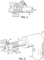
- Figure 4 shows an adapter 80 for use in holding an electrical cable clip, such as the clip 10, during the process of nailing the clip to a structure using a Spit Pulsa nail gun.
- the adapter 80 comprises a central body part 82 onto which the electrical cable clip 10 can be fitted.
- the body part 82 is situated between four legs 84.
- the body part 82 has two radiused edges 86 that lead to respective planar side faces 88. These edges 86 and side faces 88 are shaped and sized to match the profile of the channel 18 of the clip 10 so that the clip can be pushed onto the adapter and seat on the edges 84 and side faces 88.
- a groove 90 is provided in the leading end face of the body part 82 between the edges 86 to provide clearance between the adapter body part 82 and the base portion 12 of the clip.
- One of the side faces 88 is provided with a projection 92 that is arranged to fit into the opening 62 behind the locking member 40 when the clip 10 is seated on the adapter.
- the spacing of the legs 84 is such that the distance between their opposed faces in the lengthways direction of the adapter corresponds to the length of the clips with a small clearance. Accordingly the clip can be reliably supported and located on the adapter body part 82.
- the adapter body part 82 has a through-hole 94 extending perpendicular to its longitudinal axis and parallel to the legs 84.
- the through-hole 94 is adapted to receive a nozzle 96 of a nail gun.
- the illustrated embodiment is arranged to receive the nozzle of a Spit Pulsa nail gun, but it will be appreciated that the adapter body part may be adapted for connection to the nozzles of other nail guns by any suitable or desired means.
- the through-hole 94 is positioned such that the bore 98 of the nozzle 96 is aligned with the aperture 52 of a clip 10 when it is located and supported by the adapter so that a nail fired through the bore 98 will be directed through the aperture 52.
- an adapter 80 is fitted to the nozzle 96 of the nail gun 95 by pushing the adapter against the nozzle so that the nozzle penetrates the through-hole 94.
- a clip 10 is then fitted onto the adapter 80 so that it is supported and located on the adapter, with the projection 92 received in the aperture 62 in the sidewall 16.
- the adapter 80 is rotatable relative to the nozzle 96 so that the orientation of the clip can be set as desired.
- the adapter and clip are then pressed against a firm surface, such as a wall onto which the clip is to be fixed so that the adapter is pushed fully onto the nozzle.
- the adapter 80 and nozzle 96 are preferably made such that as the adapter is moved into its final installed position on the nozzle, there is an audible click.
- the clip 10 is then removed from the adapter 80 so that a visual check can be made to ensure that the adapter is correctly positioned on the nozzle.
- the nail gun can be loaded with nails and the battery fitted.
- a clip 10 is then fitted onto the adapter and the nail gun is brought into position to fix the clip to the structure 100 ( Figure 8 ), which may be the wall of a building, with the legs 84 of the adapter pressed against the surface of the structure. In this position, the projection 52 of the clip 10 will be proximate the surface (that is touching or close to) with the aperture 52 in line with the nozzle bore 98.
- the nail gun is then fired causing a nail to shoot at high velocity through the aperture 52 into the structure, thereby firmly fixing the clip in position.
- the nail head With the nail fully inserted in the structure, the nail head is received in the depression 14 below the surface of the channel 18 so that it will not interfere with cabling inserted into the clip.
- the installer will usually install a series of clips 10 in this way, thereby marking out the required cable run.
- two fire resistant cables 102 are laid side-by-side in the cable-receiving channel 18 of the first clip of the series such that they run generally parallel with one another and the sidewall 14, 16 of the clips.
- the closure member 20 is then pressed downwardly (as indicated by the arrows 42 in Figures 1 and 2 ) to bring the lip 36 alongside the sidewall 16.
- the resilience of the closure member 20 and locking member 40 are such that the lip is able to move past the locking member (primarily by deflecting the tongue) until the lip and sidewall are essentially side-by-side and the locking member 40 and aperture 38 are aligned such that the locking member can spring back through the aperture to assume the position shown in Figure 7 .
- the closure member 20 closes the opening to the channel 18 and it is locked in this closed position by the engagement of the locking member in the aperture.
- the cables 102 are thus firmly secured to the structure 100 by the electrical cable clip 10. In the same way, the cables 102 are successively installed in the remaining clips of the series to form a cable run.
- the convex portion 32 of the closure member 20 provides a convenient loop into which a screwdriver blade, or other suitable object, can be inserted to lever the closure member open, in the event that the cables are to be released. This may be desirable if one or other is damaged and needs to be replaced. It will be understood that to improve the releasability of the clip, the locking member 40 might be reconfigured so that it has two similar lead-in profiles that provide an increasing resistance to movement of the lip 36; one being operative when the closure member is being opened and the other when the closure member is being closed.
- the installer could choose to nail a clip to the structure and secure the cable(s) into that clip, before moving on to install the next clip. This will still provide considerable time savings as compared with conventional methods, but will generally not be as efficient as installing all of the clips of the cable run first, or at least all of the clips of a sub-section of a run.
- the electrical cable clip 10 is shown as being sized to receive two electrical cables side-by-side, it could instead be designed to receive only one cable or, three or more cables.
- the clip is formed with a relatively small projecting area, which makes the initial contact with the structure when the nail is fired through the aperture 52. If the structure is relatively hard, the projection provides the only point of contact with the structure, leaving the remainder of clip supported off the structure by the projecting area.
- the projection pushes into the structure to the extent the contact area may include the rear surface 12R of the clip.
- the projection pushing into the loose surface increases the area of contact around the nail in loose surfaces improving the securing of fixing for such surfaces.
- closure member 20 is an integral part of the electrical cable clip. However, it will be appreciated that it could be a separate part that would be snap-fitted or otherwise secured on the clip body so as to secure the cable(s) within the channel 18. Having an integral clip hinged to the clip body so that it can simply be pressed into its closed position provides for a speedy closure operation and avoids the problem of providing multiple parts and the time wasted in finding and attaching closure members to the clip bodies.
- closure member is provided with the two concave portions 30 and the convex portion 32, this is not essential.
- the entire centre region of the closure member could be concave in the manner of the concave portions 30, or the portion closing the opening of the channel 18 might be substantially planar. In either case, the closure member would preferably be pierced to reduce its stiffness and thereby make snap-fitting easier.
- an adapter that can reliably orient and support the electrical cable clip while it is being installed provides several advantages. Firstly, the installer does not have to provide any support for the clip and does not therefore need to put his/her hands near the clip during the nailing process. This considerably reduces the likelihood of there being an accident involving the installer's hands. Furthermore, by correctly fitting the adapter on the nozzle, the installer can have the adapter oriented relative to the nail gun such that the clips can easily be installed in the required orientation on the wall while the nail gun is held in the most convenient orientation for the nailer.
- the installer has only to change the orientation of the adapter so that the axis of the groove 90 runs in the desired direction of the cable run to be able to present the cable clip to the structure in the correct orientation without having to alter the angle of presentation of the nail gun to the structure.
- the nail gun has a 'natural vertical orientation', in which the nail gun handle 97 extends generally vertically, there is no need to change this in order to fit clips to the wall for vertical and horizontal runs. All that the installer need do is rotate the adapter 90° about the axis of the nozzle, or depending on the design of the nozzle and adapter, rotate the nozzle through the same angle.
- the electrical cable clip 10 is located and supported such that the cable-receiving channel 18 extends generally horizontally for a generally horizontal cable run.
- the adapter can be rotated through 90° so that the groove 90, and therefore the cable-receiving channel 18 extend generally vertically in parallel with the handle 97. Accordingly regardless of the desired installation of the electrical cable clip, the installation can always be made with the nail gun in its normal upright condition.
- adapter 80 is shown as being connected to the nozzle of a nail gun by push-fitting the nozzle into a bore in the adapter body, any convenient form of connection may be used. Furthermore, the nozzle and adapter may be made as one item.
- the electrical cable clip is shown as being fitted to the adapter with the adapter body received in the cable-receiving channel 18, this is not essential. All that is required is that the clip is reliably oriented and held by the adapter so that the installer can concentrate locating the clip at the desired location on the structure and operating the nail gun.
- the electrical cable clip is installed using a nail gun, it may be installed using a powered screwdriver.
- the fixing element would then preferably be a self-tapping screw capable of cutting into masonry or the like.
Landscapes
- Engineering & Computer Science (AREA)
- Architecture (AREA)
- Civil Engineering (AREA)
- Structural Engineering (AREA)
- Installation Of Indoor Wiring (AREA)
Claims (29)
- Verfahren zum Installieren von Stromverkabelung, wobei das Verfahren umfasst:Befestigen einer Stromkabel-Klemme (10) an einer Struktur unter Verwendung eines Befestigungselementes, das durch die Klemme hindurch in die Struktur eindringt, anschließend Einführen wenigstens eines Stromkabels in einen Kabelaufnahme-Kanal (18) der Klemme und Befestigen des wenigstens einen Stromkabels in dem Kanal (18), wobei der Schritt des Befestigens Betätigen eines integralen Verschlusselementes (20) der Klemme zum Schließen einer Öffnung umfasst, durch die das wenigstens eine Stromkabel in den Kanal (18) eingeführt wird, dadurch gekennzeichnet, dass das Befestigungselement ein Nagel ist und das Verfahren die folgenden Schritte umfasst:- Verbinden der Klemme mit einer Nagelpistole über eine Öffnung, die die Klemme aufweist;- Schießen des Nagels in die Struktur hinein mit der Nagelpistole, und- Herstellen von Eingriff des integralen Verschlusselementes mit einem Vorsprung (40) der Klemme, wobei der Vorsprung die Öffnung (62) bildet.
- Verfahren nach Anspruch 1, wobei der Schritt des Befestigens den Schritt des Betätigens eines Einrast-Arretiermechanismus des Verschlusselementes (20) zum Schließen der Öffnung umfasst.
- Verfahren nach Anspruch 1, wobei der Schritt des Befestigens der Stromkabel-Klemme (10) an der Struktur den Schritt des Positionierens und Aufhängens der Klemme an einem Stutzen (96) der Nagelpistole während des Schrittes des Schießens des Nagels in die Struktur hinein umfasst.
- Verfahren nach Anspruch 3, wobei die Nagelpistole eine aufrechte normale Funktionsposition hat und der Schritt des Positionierens der Stromkabel-Klemme (10) an dem Stutzen (96) der Nagelpistole den Schritt umfasst, in dem die Stromkabel-Klemme(10) so ausgerichtet wird, dass, wenn sich die Nagelpistole in der aufrechten normalen Funktionsposition befindet, der Kabelaufnahme-Kanal (18) der Stromkabel-Klemme (10) mit einer gewünschten Richtung der Lage des wenigstens einen Stromkabels fluchtend ist.
- Verfahren nach Anspruch 3 oder Anspruch 4, das umfasst, dass die Stromkabel-Klemme (10) an einem Adapter-Körper (82) positioniert wird, der auf den Stutzen (96) aufgesetzt ist.
- Verfahren nach Anspruch 5, wenn abhängig von Anspruch 4, wobei der Stutzen (96) eine Längsachse hat und der Schritt des Ausrichtens der Stromkabel-Klemme (10) Drehen des Adapter-Körpers (82) um die Längsachse herum umfasst.
- Verfahren nach Anspruch 6, das umfasst, dass der Adapter-Körper (82) gedreht wird, um eine gewünschte Ausrichtung der Stromkabel-Klemme (10) herzustellen, bevor die Klemme an dem Adapter-Körper positioniert wird.
- Verfahren nach einem der vorangehenden Ansprüche, wobei die Stromkabel-Klemme (10) einen Vorsprung (50) aufweist, der mit einer Öffnung (52) für das Befestigungselement versehen ist, und die Klemme (10) so an der Struktur befestigt wird, dass erster Kontakt zwischen der Klemme (10) und der Struktur über den Vorsprung (50) stattfindet.
- Verfahren nach einem der vorangehenden Ansprüche, wobei das Befestigungselement durch einen Bodenbereich (12) des Kabelaufnahme-Kanals (18) hindurchtritt.
- Verfahren nach einem der vorangehenden Ansprüche, wobei das wenigstens eine Stromkabel ein feuerbeständiges Stromkabel ist.
- Verfahren nach einem der vorangehenden Ansprüche, wobei der Schritt des Einführens des wenigstens einen Stromkabels umfasst, dass zwei Stromkabel so eingeführt werden, dass sie in einer im Allgemeinen nebeneinanderliegenden Beziehung angeordnet sind, und wobei die Stromkabel-Klemme (10) mit einem einzelnen Befestigungselement befestigt wird.
- Verfahren nach einem der vorangehenden Ansprüche, das umfasst, dass eine Vielzahl der Stromkabel-Klemmen (10) an der Struktur befestigt werden, um einen Kabelweg zu bilden, und anschließend das wenigstens eine Stromkabel in die jeweiligen Kabelaufnahme-Kanäle (18) der Klemmen (10) eingeführt wird.
- Verfahren nach Anspruch 1, wobei das Verfahren die folgenden Schritte umfasst:Positionieren des Körpers der Stromkabel-Klemme relativ zu der Struktur so, dass der Kabelaufnahme-Kanal (18) der Klemme (10) eine gewünschte Ausrichtung relativ zu der Struktur hat;Schießen eines Nagels aus der Nagelpistole durch eine Öffnung (52) in einem Basisbereich (12) des Kabelaufnahme-Kanals (18), so dass der Nagel die Stromkabel-Klemme an der Struktur befestigt und ein Kopf des Nagels nicht in den Kanal (18) hinein vorsteht;Einführen des wenigstens einen Stromkabels durch eine Öffnung in den Kabelaufnahme-Kanal (18) hinein, so dass das Kabel an dem Basisbereich (12) anliegt; undPressen des Verschlusselementes (20) auf die Öffnung des Kabelaufnahme-Kanals (18) und Einrasten des Verschlusselementes (20) in arretierenden Eingriff mit dem Körper (10) der Stromkabel-Klemme, so dass das wenigstens eine Stromkabel in dem Kabelaufnahme-Kanal (18) befestigt ist.
- Verfahren nach Anspruch 1, wobei das Verfahren die folgenden Schritte umfasst:Positionieren der Stromkabel-Klemme (10) an einem Stutzen (96) der Nagelpistole, so dass ein länglicher Kabelaufnahme-Kanal (18) der Klemme (10) eine gewünschte Ausrichtung relativ zu einer normalen aufrechten Funktionsposition der Nagelpistole hat;Anordnen der Stromkabel-Klemme (10) nahe an der Struktur, an der sie befestigt werden soll, wobei sich die Nagelpistole in der aufrechten Funktionsposition befindet, und Schießen eines Nagels von der Nagelpistole durch einen Basisbereich (12) der Stromkabel-Klemme (10) in die Struktur hinein;Einführen des wenigstens einen Stromkabels durch eine Öffnung in den Kabelaufnahme-Kanal (18) hinein; undSchließen der Öffnung zum Befestigen des wenigstens einen Stromkabels in dem Kabelaufnahme-Kanal (18) durch Einrasten des Verschlusselementes (20) an einer Position, an der es die Öffnung verschließt.
- Verfahren nach Anspruch 14, wobei sich die Stromkabelklemme (10) an einem Körper (82) befindet, der mit dem Stutzen (96) verbunden ist, und der Körper relativ zu dem Stutzen (96) bewegt werden kann, um Ausrichtung der Stromkabel-Klemme (10) zu ermöglichen.
- Stromkabel-Klemme (10) zum Befestigen von Stromverkabelung an einer Struktur, wobei die Klemme (10) so eingerichtet ist, dass sie wenigstens ein Stromkabel unter Verwendung eines integralen Verschlusselementes (20) aufnimmt und befestigt, und eine Rückseite (12R) hat, die mit einem ersten Vorsprung (50) versehen ist, wobei der erste Vorsprung (50) mit einer Öffnung (52) für ein Befestigungselement versehen ist und die Anordnung so ist, dass in Funktion erster Kontakt zwischen der Klemme (10) und der Struktur über den ersten Vorsprung (50) stattfindet, wobei die Klemme einen Körper hat, der einen Basisabschnitt (12) und einander gegenüberliegende Seitenwände (14, 16) umfasst, die von dem Basisabschnitt (12) vorstehen und einen Kanal (18) zum Aufnehmen des wenigstens einen Stromkabels bilden, und das Verschlusselement (20) das wenigstens eine Stromkabel in dem Kanal (18) befestigt, dadurch gekennzeichnet, dass das Befestigungselement ein Nagel ist und die Klemme einen zweiten Vorsprung (40) umfasst, der mit dem integralen Verschlusselement (20) in Eingriff kommt, wobei der zweite Vorsprung (40) eine Öffnung (62) in dem Körper bildet.
- Klemme nach Anspruch 16, wobei der erste Vorsprung (50) eine Aussparung in dem Basisabschnitt (12) zum Aufnehmen eines Kopfes des Befestigungselementes bildet.
- Klemme nach Anspruch 17, wobei der erste Vorsprung (50) im Allgemeinen mittig an dem Basisabschnitt angeordnet ist.
- Klemme nach Anspruch 17, wobei das Verschlusselement (20) an einer der Seitenwände angelenkt ist.
- Klemme nach Anspruch 19, wobei das Verschlusselement (20) integral mit der einen der Seitenwände (14) verbunden ist und das Gelenk (22) durch Perforationen (24) an einer Verbindung zwischen dem Verschlusselement (20) und der einen der Seitenwände (14) gebildet wird.
- Klemme nach Anspruch 20, wobei die Perforationen (24) im Allgemeinen rautenförmig sind.
- Klemme nach einem der Ansprüche 16 bis 21, wobei die Klemme aus Metall besteht und einen Einrast-Arretiermechanismus zum Fixieren des Verschlusselementes (20) in einer geschlossenen Position umfasst, in der es das wenigstens eine Stromkabel in dem Kanal (18) fixiert, wobei der Einrast-Arretiermechanismus den zweiten Vorsprung (40) an dem Körper umfasst, der so eingerichtet ist, dass er in eine Öffnung (38) einrastet, die durch das Verschlusselement (20) gebildet wird.
- Klemme nach Anspruch 22, wobei das Verschlusselement (20) eine Wand (36) umfasst, die so eingerichtet ist, dass sie in der verschlossenen Position an die Seitenwand (16) angrenzend angeordnet ist, wobei der zweite Vorsprung (40) in einem schiefen Winkel von der angrenzenden Seitenwand (16) vorsteht und die Öffnung (38) durch einen Schlitz in der Wand (36) des Verschlusselementes gebildet wird.
- Klemme nach einem der Ansprüche 16 bis 23, wobei das Verschlusselement (20) zwei konkave Endabschnitte (30) und einen konvexen Abschnitt (32) umfasst, der die konkaven trennt.
- Klemme nach Anspruch 24, wobei das Verschlusselement (20) zwei flache Seitenabschnitte (26, 28) umfasst, die sich parallel in der Längsrichtung der Klemme (10) erstrecken und durch einen Mittelabschnitt miteinander verbunden sind, der die konkaven Endabschnitte (30) und den konvexen Abschnitt umfasst.
- Klemme nach einem der Ansprüche 16 bis 25, wobei der zweite Vorsprung (40) von dem Kanal (18) weg vorsteht.
- Klemme nach einem der Ansprüche 16 bis 26, wobei die durch den zweiten Vorsprung (40) gebildete Öffnung (62) dazu dient, die Klemme an einer Nagelpistole zu positionieren.
- Stromkabel-Installation, die wenigstens ein Stromkabel umfasst, das mit einer Vielzahl von Stromkabel-Klemmen (10) nach einem der Ansprüche 16 bis 27 an einer Struktur befestigt ist.
- Verfahren nach einem der Ansprüche 1 bis 15, bei dem eine Klemme (10) nach einem der Ansprüche 16 bis 26 eingesetzt wird.
Applications Claiming Priority (1)
| Application Number | Priority Date | Filing Date | Title |
|---|---|---|---|
| PCT/GB2003/003360 WO2005015703A1 (en) | 2003-07-30 | 2003-07-30 | Improvements relating to cable installation |
Publications (2)
| Publication Number | Publication Date |
|---|---|
| EP1652279A1 EP1652279A1 (de) | 2006-05-03 |
| EP1652279B1 true EP1652279B1 (de) | 2017-05-24 |
Family
ID=34130888
Family Applications (1)
| Application Number | Title | Priority Date | Filing Date |
|---|---|---|---|
| EP03817972.7A Expired - Lifetime EP1652279B1 (de) | 2003-07-30 | 2003-07-30 | Verbesserungen für kabelinstallation |
Country Status (6)
| Country | Link |
|---|---|
| US (1) | US7676899B2 (de) |
| EP (1) | EP1652279B1 (de) |
| AU (1) | AU2003252961A1 (de) |
| CA (1) | CA2542929C (de) |
| ES (1) | ES2637912T3 (de) |
| WO (1) | WO2005015703A1 (de) |
Families Citing this family (18)
| Publication number | Priority date | Publication date | Assignee | Title |
|---|---|---|---|---|
| WO2006036186A2 (en) * | 2004-09-15 | 2006-04-06 | S.M.A.R.T. Link Medical, Inc. | Collections of linked databases |
| US7685676B2 (en) * | 2006-02-24 | 2010-03-30 | Mc Clellan W Thomas | Living hinge |
| JP2007273864A (ja) * | 2006-03-31 | 2007-10-18 | Sony Corp | ケーブル固定具 |
| MX2013015142A (es) * | 2011-06-24 | 2015-05-07 | Scorpius Trackers Private Ltd | Articulacion para aparatos de seguimiento solar. |
| WO2015142824A1 (en) | 2014-03-17 | 2015-09-24 | Intuitive Surgical Operations, Inc. | Surgical drape and systems including surgical drape and attachment sensor |
| NL2015404B1 (en) * | 2015-09-07 | 2017-03-22 | Walraven Holding Bv J Van | Conduit clip. |
| GB2553491A (en) * | 2016-06-22 | 2018-03-14 | Cip Fastening Systems Ltd | Cable bracket |
| US11883123B2 (en) * | 2016-07-14 | 2024-01-30 | Intuitive Surgical Operations, Inc. | Mechanism for managing and retaining a surgical drape |
| CN108270177B (zh) * | 2016-12-30 | 2020-08-18 | 喜利得股份公司 | 保持器 |
| CN108270176A (zh) * | 2016-12-30 | 2018-07-10 | 喜利得股份公司 | 保持器 |
| CN108266570B (zh) | 2016-12-30 | 2020-04-07 | 喜利得股份公司 | 保持器 |
| DE102018213596B3 (de) * | 2018-08-13 | 2019-12-24 | Bayerische Motoren Werke Aktiengesellschaft | Leitungsinstallationseinrichtung für eine Hochvoltbatterie eines Kraftfahrzeugs, Leitungsanordnung, Hochvoltbatterie sowie Kraftfahrzeug |
| US11061195B2 (en) * | 2018-09-21 | 2021-07-13 | Ofs Fitel, Llc | Fire safety retainers for point of entry and other modules storing optical fibers or cables |
| US10765024B2 (en) * | 2018-12-18 | 2020-09-01 | Microsoft Technology Licensing, Llc | Hinged chassis with a uniform stress hinge |
| US11099342B2 (en) * | 2019-01-03 | 2021-08-24 | Ofs Fitel, Llc | Safety guard device for modules storing communication lines |
| US20200338709A1 (en) * | 2019-04-23 | 2020-10-29 | Erico International Corporation | Systems and Methods for a Bracket for a Nail Gun |
| CN113359958A (zh) * | 2021-05-31 | 2021-09-07 | 浪潮电子信息产业股份有限公司 | 服务器、板卡模组及理线夹 |
| IT202200022995A1 (it) * | 2022-11-08 | 2024-05-08 | Ind I A S P A | Pinza perfezionata per la composizione di strutture tecniche di arredo, protezione e/o delimitazione |
Family Cites Families (10)
| Publication number | Priority date | Publication date | Assignee | Title |
|---|---|---|---|---|
| US2886815A (en) * | 1954-12-13 | 1959-05-19 | Powers Wire Products Company | Clip applicating gun |
| CH492889A (de) * | 1968-07-18 | 1970-06-30 | Gunnebo Bruks Ab | Zum Festnageln mittels eines Nageleintreibgerätes vorgesehene Halteklemme |
| DE2334913A1 (de) * | 1973-07-10 | 1975-01-23 | Bassan & Cie | Vorrichtung zum befestigen zylindrischer, insbesondere rohrfoermiger teile auf einer beliebigen unterlage |
| US3883064A (en) * | 1974-03-29 | 1975-05-13 | Thomas M Hilgers | Bracket setting tool |
| DE3117913A1 (de) * | 1981-05-06 | 1982-11-25 | Tucker Gmbh, 6300 Giessen | "rohrschelle" |
| SE430551B (sv) | 1982-04-05 | 1983-11-21 | Ahlstroem Foeretagen | Verktyg for festande av en el-, tele- eller liknande kabel eller ledning pa ett underlag med hjelp av klammer |
| US4655423A (en) * | 1985-06-03 | 1987-04-07 | Illinois Tool Works Inc. | Plastic clip with integral nail |
| DE3624993A1 (de) | 1986-07-24 | 1988-01-28 | Robert Stadler | Befestigungselemente fuer installationsmaterial |
| US5113717A (en) * | 1991-01-30 | 1992-05-19 | Teleflex Incorporated | Motion transmitting remote control assembly with a conduit locator connecting means |
| DE4216466C1 (en) * | 1992-05-19 | 1993-08-19 | Techno - Plast, 7121 Mundelsheim, De | Plastics fixing clip for electric cable or hose - has closure element locked in place after insertion of cable or hose to prevent removal by applied tension |
-
2003
- 2003-07-30 EP EP03817972.7A patent/EP1652279B1/de not_active Expired - Lifetime
- 2003-07-30 US US10/566,387 patent/US7676899B2/en not_active Expired - Lifetime
- 2003-07-30 CA CA2542929A patent/CA2542929C/en not_active Expired - Lifetime
- 2003-07-30 WO PCT/GB2003/003360 patent/WO2005015703A1/en not_active Ceased
- 2003-07-30 AU AU2003252961A patent/AU2003252961A1/en not_active Abandoned
- 2003-07-30 ES ES03817972.7T patent/ES2637912T3/es not_active Expired - Lifetime
Also Published As
| Publication number | Publication date |
|---|---|
| AU2003252961A1 (en) | 2005-02-25 |
| CA2542929C (en) | 2012-04-10 |
| US7676899B2 (en) | 2010-03-16 |
| WO2005015703A1 (en) | 2005-02-17 |
| ES2637912T3 (es) | 2017-10-17 |
| CA2542929A1 (en) | 2005-02-17 |
| EP1652279A1 (de) | 2006-05-03 |
| US20070137882A1 (en) | 2007-06-21 |
Similar Documents
| Publication | Publication Date | Title |
|---|---|---|
| CA2542929C (en) | Improvements relating to cable installation | |
| US5898987A (en) | Method of installing acoustical ceiling grid | |
| US6364266B1 (en) | Universal electrical wire hanger | |
| US4434597A (en) | Fastening device | |
| US6889944B2 (en) | Cable to frame fastener system | |
| EP3596283B1 (de) | Plattensystem | |
| EP3649302B1 (de) | Ankerkonstruktion | |
| CN101542139A (zh) | 墙壁和天花板紧固用的系统和方法 | |
| US9765529B2 (en) | Panel fastener | |
| US7926232B2 (en) | Installation bracket and system for crown molding | |
| US20170121972A1 (en) | Panel fixing assembly | |
| US2673980A (en) | Strap and means for mounting the same | |
| RU2317764C2 (ru) | Система, зажимной элемент и запирающий элемент для соединения профильных элементов | |
| EP3577287B1 (de) | Sicherungsanordnung | |
| US7134253B2 (en) | Siding installation apparatuses and methods for installing siding pieces on walls | |
| US6513286B2 (en) | Tool for hanging fascia board | |
| US6286286B1 (en) | Apparatus for mounting architectural moldings | |
| GB2467764A (en) | Panel clamping jaw for railing assembly | |
| GB2135044A (en) | Louvre and mullion system | |
| AU2010241518A1 (en) | Mounting assembly and bracket for an electrical power outlet or alike | |
| WO1985003560A1 (en) | Clips, fastener for pipes, cables etc. in porous materials, e.g. plaster board | |
| EP2550473B1 (de) | Klemme | |
| CN118076785A (zh) | 夹具和夹具安装设备 | |
| US20260076478A1 (en) | Cabinet Installation Mechanism | |
| EP1906500B1 (de) | Einbaudose mit Deckel |
Legal Events
| Date | Code | Title | Description |
|---|---|---|---|
| PUAI | Public reference made under article 153(3) epc to a published international application that has entered the european phase |
Free format text: ORIGINAL CODE: 0009012 |
|
| 17P | Request for examination filed |
Effective date: 20060228 |
|
| AK | Designated contracting states |
Kind code of ref document: A1 Designated state(s): AT BE BG CH CY CZ DE DK EE ES FI FR GB GR HU IE IT LI LU MC NL PT RO SE SI SK TR |
|
| DAX | Request for extension of the european patent (deleted) | ||
| 17Q | First examination report despatched |
Effective date: 20061117 |
|
| RAP1 | Party data changed (applicant data changed or rights of an application transferred) |
Owner name: PRYSMIAN CABLES & SYSTEMS LIMITED |
|
| GRAP | Despatch of communication of intention to grant a patent |
Free format text: ORIGINAL CODE: EPIDOSNIGR1 |
|
| STAA | Information on the status of an ep patent application or granted ep patent |
Free format text: STATUS: GRANT OF PATENT IS INTENDED |
|
| INTG | Intention to grant announced |
Effective date: 20161206 |
|
| GRAS | Grant fee paid |
Free format text: ORIGINAL CODE: EPIDOSNIGR3 |
|
| GRAA | (expected) grant |
Free format text: ORIGINAL CODE: 0009210 |
|
| STAA | Information on the status of an ep patent application or granted ep patent |
Free format text: STATUS: THE PATENT HAS BEEN GRANTED |
|
| AK | Designated contracting states |
Kind code of ref document: B1 Designated state(s): AT BE BG CH CY CZ DE DK EE ES FI FR GB GR HU IE IT LI LU MC NL PT RO SE SI SK TR |
|
| REG | Reference to a national code |
Ref country code: GB Ref legal event code: FG4D |
|
| REG | Reference to a national code |
Ref country code: CH Ref legal event code: EP |
|
| REG | Reference to a national code |
Ref country code: IE Ref legal event code: FG4D |
|
| REG | Reference to a national code |
Ref country code: AT Ref legal event code: REF Ref document number: 896435 Country of ref document: AT Kind code of ref document: T Effective date: 20170615 |
|
| REG | Reference to a national code |
Ref country code: DE Ref legal event code: R096 Ref document number: 60350269 Country of ref document: DE |
|
| REG | Reference to a national code |
Ref country code: FR Ref legal event code: PLFP Year of fee payment: 15 |
|
| REG | Reference to a national code |
Ref country code: NL Ref legal event code: FP |
|
| REG | Reference to a national code |
Ref country code: AT Ref legal event code: MK05 Ref document number: 896435 Country of ref document: AT Kind code of ref document: T Effective date: 20170524 |
|
| REG | Reference to a national code |
Ref country code: ES Ref legal event code: FG2A Ref document number: 2637912 Country of ref document: ES Kind code of ref document: T3 Effective date: 20171017 |
|
| PG25 | Lapsed in a contracting state [announced via postgrant information from national office to epo] |
Ref country code: GR Free format text: LAPSE BECAUSE OF FAILURE TO SUBMIT A TRANSLATION OF THE DESCRIPTION OR TO PAY THE FEE WITHIN THE PRESCRIBED TIME-LIMIT Effective date: 20170825 Ref country code: AT Free format text: LAPSE BECAUSE OF FAILURE TO SUBMIT A TRANSLATION OF THE DESCRIPTION OR TO PAY THE FEE WITHIN THE PRESCRIBED TIME-LIMIT Effective date: 20170524 Ref country code: FI Free format text: LAPSE BECAUSE OF FAILURE TO SUBMIT A TRANSLATION OF THE DESCRIPTION OR TO PAY THE FEE WITHIN THE PRESCRIBED TIME-LIMIT Effective date: 20170524 |
|
| PG25 | Lapsed in a contracting state [announced via postgrant information from national office to epo] |
Ref country code: SE Free format text: LAPSE BECAUSE OF FAILURE TO SUBMIT A TRANSLATION OF THE DESCRIPTION OR TO PAY THE FEE WITHIN THE PRESCRIBED TIME-LIMIT Effective date: 20170524 Ref country code: BG Free format text: LAPSE BECAUSE OF FAILURE TO SUBMIT A TRANSLATION OF THE DESCRIPTION OR TO PAY THE FEE WITHIN THE PRESCRIBED TIME-LIMIT Effective date: 20170824 |
|
| PG25 | Lapsed in a contracting state [announced via postgrant information from national office to epo] |
Ref country code: RO Free format text: LAPSE BECAUSE OF FAILURE TO SUBMIT A TRANSLATION OF THE DESCRIPTION OR TO PAY THE FEE WITHIN THE PRESCRIBED TIME-LIMIT Effective date: 20170524 Ref country code: EE Free format text: LAPSE BECAUSE OF FAILURE TO SUBMIT A TRANSLATION OF THE DESCRIPTION OR TO PAY THE FEE WITHIN THE PRESCRIBED TIME-LIMIT Effective date: 20170524 Ref country code: CZ Free format text: LAPSE BECAUSE OF FAILURE TO SUBMIT A TRANSLATION OF THE DESCRIPTION OR TO PAY THE FEE WITHIN THE PRESCRIBED TIME-LIMIT Effective date: 20170524 Ref country code: DK Free format text: LAPSE BECAUSE OF FAILURE TO SUBMIT A TRANSLATION OF THE DESCRIPTION OR TO PAY THE FEE WITHIN THE PRESCRIBED TIME-LIMIT Effective date: 20170524 Ref country code: SK Free format text: LAPSE BECAUSE OF FAILURE TO SUBMIT A TRANSLATION OF THE DESCRIPTION OR TO PAY THE FEE WITHIN THE PRESCRIBED TIME-LIMIT Effective date: 20170524 |
|
| REG | Reference to a national code |
Ref country code: DE Ref legal event code: R097 Ref document number: 60350269 Country of ref document: DE |
|
| REG | Reference to a national code |
Ref country code: CH Ref legal event code: PL |
|
| PLBE | No opposition filed within time limit |
Free format text: ORIGINAL CODE: 0009261 |
|
| STAA | Information on the status of an ep patent application or granted ep patent |
Free format text: STATUS: NO OPPOSITION FILED WITHIN TIME LIMIT |
|
| PG25 | Lapsed in a contracting state [announced via postgrant information from national office to epo] |
Ref country code: LI Free format text: LAPSE BECAUSE OF NON-PAYMENT OF DUE FEES Effective date: 20170731 Ref country code: CH Free format text: LAPSE BECAUSE OF NON-PAYMENT OF DUE FEES Effective date: 20170731 |
|
| 26N | No opposition filed |
Effective date: 20180227 |
|
| REG | Reference to a national code |
Ref country code: IE Ref legal event code: MM4A |
|
| PG25 | Lapsed in a contracting state [announced via postgrant information from national office to epo] |
Ref country code: SI Free format text: LAPSE BECAUSE OF FAILURE TO SUBMIT A TRANSLATION OF THE DESCRIPTION OR TO PAY THE FEE WITHIN THE PRESCRIBED TIME-LIMIT Effective date: 20170524 |
|
| REG | Reference to a national code |
Ref country code: BE Ref legal event code: MM Effective date: 20170731 |
|
| PG25 | Lapsed in a contracting state [announced via postgrant information from national office to epo] |
Ref country code: LU Free format text: LAPSE BECAUSE OF NON-PAYMENT OF DUE FEES Effective date: 20170730 |
|
| REG | Reference to a national code |
Ref country code: FR Ref legal event code: PLFP Year of fee payment: 16 |
|
| PG25 | Lapsed in a contracting state [announced via postgrant information from national office to epo] |
Ref country code: IE Free format text: LAPSE BECAUSE OF NON-PAYMENT OF DUE FEES Effective date: 20170730 |
|
| PG25 | Lapsed in a contracting state [announced via postgrant information from national office to epo] |
Ref country code: BE Free format text: LAPSE BECAUSE OF NON-PAYMENT OF DUE FEES Effective date: 20170731 |
|
| PG25 | Lapsed in a contracting state [announced via postgrant information from national office to epo] |
Ref country code: HU Free format text: LAPSE BECAUSE OF FAILURE TO SUBMIT A TRANSLATION OF THE DESCRIPTION OR TO PAY THE FEE WITHIN THE PRESCRIBED TIME-LIMIT; INVALID AB INITIO Effective date: 20030730 Ref country code: MC Free format text: LAPSE BECAUSE OF FAILURE TO SUBMIT A TRANSLATION OF THE DESCRIPTION OR TO PAY THE FEE WITHIN THE PRESCRIBED TIME-LIMIT Effective date: 20170524 |
|
| PG25 | Lapsed in a contracting state [announced via postgrant information from national office to epo] |
Ref country code: CY Free format text: LAPSE BECAUSE OF NON-PAYMENT OF DUE FEES Effective date: 20170524 |
|
| PG25 | Lapsed in a contracting state [announced via postgrant information from national office to epo] |
Ref country code: TR Free format text: LAPSE BECAUSE OF FAILURE TO SUBMIT A TRANSLATION OF THE DESCRIPTION OR TO PAY THE FEE WITHIN THE PRESCRIBED TIME-LIMIT Effective date: 20170524 |
|
| PG25 | Lapsed in a contracting state [announced via postgrant information from national office to epo] |
Ref country code: PT Free format text: LAPSE BECAUSE OF FAILURE TO SUBMIT A TRANSLATION OF THE DESCRIPTION OR TO PAY THE FEE WITHIN THE PRESCRIBED TIME-LIMIT Effective date: 20170524 |
|
| PGFP | Annual fee paid to national office [announced via postgrant information from national office to epo] |
Ref country code: NL Payment date: 20220726 Year of fee payment: 20 |
|
| PGFP | Annual fee paid to national office [announced via postgrant information from national office to epo] |
Ref country code: IT Payment date: 20220721 Year of fee payment: 20 Ref country code: GB Payment date: 20220727 Year of fee payment: 20 Ref country code: ES Payment date: 20220801 Year of fee payment: 20 Ref country code: DE Payment date: 20220727 Year of fee payment: 20 |
|
| PGFP | Annual fee paid to national office [announced via postgrant information from national office to epo] |
Ref country code: FR Payment date: 20220725 Year of fee payment: 20 |
|
| REG | Reference to a national code |
Ref country code: DE Ref legal event code: R071 Ref document number: 60350269 Country of ref document: DE |
|
| REG | Reference to a national code |
Ref country code: NL Ref legal event code: MK Effective date: 20230729 |
|
| REG | Reference to a national code |
Ref country code: ES Ref legal event code: FD2A Effective date: 20230804 |
|
| REG | Reference to a national code |
Ref country code: GB Ref legal event code: PE20 Expiry date: 20230729 |
|
| PG25 | Lapsed in a contracting state [announced via postgrant information from national office to epo] |
Ref country code: GB Free format text: LAPSE BECAUSE OF EXPIRATION OF PROTECTION Effective date: 20230729 Ref country code: ES Free format text: LAPSE BECAUSE OF EXPIRATION OF PROTECTION Effective date: 20230731 |