EP1652458A2 - Unité collecteur de poussière pour aspirateur - Google Patents
Unité collecteur de poussière pour aspirateur Download PDFInfo
- Publication number
- EP1652458A2 EP1652458A2 EP05110053A EP05110053A EP1652458A2 EP 1652458 A2 EP1652458 A2 EP 1652458A2 EP 05110053 A EP05110053 A EP 05110053A EP 05110053 A EP05110053 A EP 05110053A EP 1652458 A2 EP1652458 A2 EP 1652458A2
- Authority
- EP
- European Patent Office
- Prior art keywords
- dust collection
- air
- guide plate
- collection unit
- airflow
- Prior art date
- Legal status (The legal status is an assumption and is not a legal conclusion. Google has not performed a legal analysis and makes no representation as to the accuracy of the status listed.)
- Granted
Links
Images

Classifications
-
- A—HUMAN NECESSITIES
- A47—FURNITURE; DOMESTIC ARTICLES OR APPLIANCES; COFFEE MILLS; SPICE MILLS; SUCTION CLEANERS IN GENERAL
- A47L—DOMESTIC WASHING OR CLEANING; SUCTION CLEANERS IN GENERAL
- A47L9/00—Details or accessories of suction cleaners, e.g. mechanical means for controlling the suction or for effecting pulsating action; Storing devices specially adapted to suction cleaners or parts thereof; Carrying-vehicles specially adapted for suction cleaners
- A47L9/10—Filters; Dust separators; Dust removal; Automatic exchange of filters
-
- A—HUMAN NECESSITIES
- A47—FURNITURE; DOMESTIC ARTICLES OR APPLIANCES; COFFEE MILLS; SPICE MILLS; SUCTION CLEANERS IN GENERAL
- A47L—DOMESTIC WASHING OR CLEANING; SUCTION CLEANERS IN GENERAL
- A47L9/00—Details or accessories of suction cleaners, e.g. mechanical means for controlling the suction or for effecting pulsating action; Storing devices specially adapted to suction cleaners or parts thereof; Carrying-vehicles specially adapted for suction cleaners
- A47L9/10—Filters; Dust separators; Dust removal; Automatic exchange of filters
- A47L9/16—Arrangement or disposition of cyclones or other devices with centrifugal action
- A47L9/1683—Dust collecting chambers; Dust collecting receptacles
-
- A—HUMAN NECESSITIES
- A47—FURNITURE; DOMESTIC ARTICLES OR APPLIANCES; COFFEE MILLS; SPICE MILLS; SUCTION CLEANERS IN GENERAL
- A47L—DOMESTIC WASHING OR CLEANING; SUCTION CLEANERS IN GENERAL
- A47L9/00—Details or accessories of suction cleaners, e.g. mechanical means for controlling the suction or for effecting pulsating action; Storing devices specially adapted to suction cleaners or parts thereof; Carrying-vehicles specially adapted for suction cleaners
- A47L9/10—Filters; Dust separators; Dust removal; Automatic exchange of filters
- A47L9/16—Arrangement or disposition of cyclones or other devices with centrifugal action
- A47L9/1616—Multiple arrangement thereof
- A47L9/1625—Multiple arrangement thereof for series flow
-
- A—HUMAN NECESSITIES
- A47—FURNITURE; DOMESTIC ARTICLES OR APPLIANCES; COFFEE MILLS; SPICE MILLS; SUCTION CLEANERS IN GENERAL
- A47L—DOMESTIC WASHING OR CLEANING; SUCTION CLEANERS IN GENERAL
- A47L9/00—Details or accessories of suction cleaners, e.g. mechanical means for controlling the suction or for effecting pulsating action; Storing devices specially adapted to suction cleaners or parts thereof; Carrying-vehicles specially adapted for suction cleaners
- A47L9/10—Filters; Dust separators; Dust removal; Automatic exchange of filters
- A47L9/16—Arrangement or disposition of cyclones or other devices with centrifugal action
- A47L9/1616—Multiple arrangement thereof
- A47L9/1641—Multiple arrangement thereof for parallel flow
-
- B—PERFORMING OPERATIONS; TRANSPORTING
- B04—CENTRIFUGAL APPARATUS OR MACHINES FOR CARRYING-OUT PHYSICAL OR CHEMICAL PROCESSES
- B04C—APPARATUS USING FREE VORTEX FLOW, e.g. CYCLONES
- B04C5/00—Apparatus in which the axial direction of the vortex is reversed
- B04C5/08—Vortex chamber constructions
- B04C5/103—Bodies or members, e.g. bulkheads, guides, in the vortex chamber
-
- B—PERFORMING OPERATIONS; TRANSPORTING
- B04—CENTRIFUGAL APPARATUS OR MACHINES FOR CARRYING-OUT PHYSICAL OR CHEMICAL PROCESSES
- B04C—APPARATUS USING FREE VORTEX FLOW, e.g. CYCLONES
- B04C5/00—Apparatus in which the axial direction of the vortex is reversed
- B04C5/14—Construction of the underflow ducting; Apex constructions; Discharge arrangements ; discharge through sidewall provided with a few slits or perforations
- B04C5/185—Dust collectors
-
- B—PERFORMING OPERATIONS; TRANSPORTING
- B04—CENTRIFUGAL APPARATUS OR MACHINES FOR CARRYING-OUT PHYSICAL OR CHEMICAL PROCESSES
- B04C—APPARATUS USING FREE VORTEX FLOW, e.g. CYCLONES
- B04C5/00—Apparatus in which the axial direction of the vortex is reversed
- B04C5/24—Multiple arrangement thereof
- B04C5/26—Multiple arrangement thereof for series flow
-
- B—PERFORMING OPERATIONS; TRANSPORTING
- B04—CENTRIFUGAL APPARATUS OR MACHINES FOR CARRYING-OUT PHYSICAL OR CHEMICAL PROCESSES
- B04C—APPARATUS USING FREE VORTEX FLOW, e.g. CYCLONES
- B04C9/00—Combinations with other devices, e.g. fans, expansion chambers, diffusors, water locks
- B04C2009/004—Combinations with other devices, e.g. fans, expansion chambers, diffusors, water locks with internal filters, in the cyclone chamber or in the vortex finder
Definitions
- the present invention relates to a vacuum cleaner, and particularly, to a dust collection unit of a vacuum cleaner, which has a first dust collection part for filtering relatively large foreign objects and a second dust collection part for filtering relatively small foreign objects, the first and second dust collection parts being separated from each other.
- the present invention further relates to a dust collection unit for a vacuum cleaner, which is designed in a proper size and shape so that it can be easily mounted in a main body of the vacuum cleaner.
- a vacuum cleaner is used to clean a room or other spaces by sucking air containing foreign objects and filtering the foreign object using vacuum pressure generated therein.
- a dust collection unit is provided in the vacuum cleaner and a paper filter designed with a predetermined structure is provided in the dust collection unit.
- the paper filter is formed of porous material so that the foreign objects are filtered while the air containing the foreign objects passes through the filter.
- a cyclone type vacuum cleaner has been recently proposed.
- outer air containing foreign objects is sucked through a suction nozzle is directed to a collection chamber through a suction guide. Since the suction guide extends in a tangential direction of the collection chamber, the sucked air containing the foreign objects spirally rotates in the collection chamber, in the course of which relatively heavy foreign objects falls downward. Then, the air passes through a filter member, in the course of which relatively small foreign objects contained in the air are filtered by the filter.
- the present invention is directed to a dust collection unit for a vacuum cleaner that substantially obviates one or more problems due to limitations and disadvantages of the related art.
- An object of the present invention is to provide a dust collection unit for a vacuum cleaner, in which an arrangement of a dust collection part is optimized.
- Another object of the present invention is to provide a dust collection unit for a vacuum cleaner, which can effectively filter small foreign objects as well as large foreign objects, thereby improving the dust collection efficiency.
- a dust collection unit for a vacuum cleaner including: a first dust collection part for filtering foreign objects in air; a second dust collection part for filtering foreign objects in the air that has passed through the first dust collection part; and a dust collection container having first and second dust collection chambers that correspond to the first and second dust collection parts, respectively, wherein the first and second dust collection chambers store the foreign objects filtered by the respective first and second dust collection parts in a state where parts of the respective first and second dust collection parts are received in the respective first and second dust collection chambers and the first and second dust collection chambers are provided in a line.
- a dust collection unit for a vacuum cleaner including: a dust collection container provided with first and second dust collection chambers divided from each other and arranged in a line; a bottom cover for opening and closing a lower portion of the dust collection container; an airflow guide plate provided above the dust collection plate to guide the air that has passed through the first dust collection chamber to the second dust collection chamber; a plurality of small cyclones extending downward from the airflow guide plate and opened toward the second dust collection chamber; a discharge guide tube for receiving a part of each small cyclone and guiding the air that has passed through the small cyclones upward; an exhaust guide plate integrally formed with the discharge guide tube to cover the airflow guide plate; and a top cover provided above the exhaust guide plate to guide the air discharged through the discharge guide tube to an external side.
- a dust collection unit for a vacuum cleaner comprising: a dust collection container provided with first and second dust collection chambers divided from each other and arranged in a line; a bottom cover for opening and closing a lower portion of the dust collection container; an airflow guide plate provided above the dust collection plate to guide the airflow; a plurality of small cyclones extending downward from the airflow guide plate to filter minute particles contained in the air; a discharge guide tube for guiding the air that has passed through the small cyclones upward; an exhaust guide plate integrally formed with the discharge guide tube to cover the airflow guide plate; and a top cover provided above the exhaust guide plate to guide the air discharged through the discharge guide tube to an external side.
- a dust collection unit for a vacuum cleaner including: a dust collection container provided with first and second dust collection chambers divided from each other and arranged in a line; an airflow guide plate provided above the dust collection plate to guide the airflow; a plurality of small cyclones extending downward from the airflow guide plate to filter minute particles contained in the air; a discharge guide tube for guiding the air that has passed through the small cyclones upward; and an exhaust guide plate integrally formed with the discharge guide tube to cover the airflow guide plate, wherein outer edges of the dust collection container, the airflow guide plate and the exhaust guide plate are formed to be similar to each other.
- the dust collection efficiency is improved.
- the airflow resistance can be reduced to improve the dust collection efficiency.
- the collected foreign objects can be exhausted by opening a lower cover, thereby further improving the user's convenience.
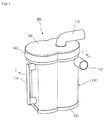
- FIG. 1 is a perspective view of a dust collection unit according to an embodiment of the present invention
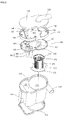
- FIG. 2 is an exploded perspective view of a dust collection unit depicted in FIG. 1;
- FIG. 3 is a bottom perspective view of an air exhaust guide plate depicted in FIG. 2;
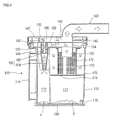
- FIG. 4 is a sectional view taken along line I-I' of FIG. 1;
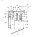
- FIG. 5 is a view illustrating a state where collected foreign objects are removed from the dust collection unit according to the present invention.
- FIGs. 1 and 2 show a dust collection unit according to an embodiment of the present invention.
- the inventive dust collection unit includes a dust collection container 110 having an 8-shaped section.
- An inner space of the dust collection container 110 is divided into first and second dust collection chambers 111 and 112 that are arranged in a line and designed to respectively receive first and second dust collection parts that will be described later.
- a barrier 113 is formed between the first and second dust collection chamber 111 and 112.
- the barrier 113 is curved toward the second dust collection chamber 112 such that the first collection chamber 111 can be formed in a cylindrical shape. Therefore, a horizontal section of the first dust collection chamber 111 is formed in a circular shape by which cyclone airflow occurs in the first dust collection chamber 111.
- the first and second dust collection chambers 111 and 112 are arranged in a line, a length of the dust collection unit is increased while a width is reduced. That is, a section of the dust collection unit is generally formed to be relatively flat. Therefore, when the dust collection unit can be easily inserted even in an upright type vacuum cleaner having a relatively narrow width. For example, when the dust collection unit 100 is inserted in the upright type vacuum cleaner, it becomes possible that the first dust collection chamber 111 is disposed in the vacuum cleaner while the second dust collection chamber 112 is projected out of the vacuum cleaner, making it easy to mount the dust collection unit in the vacuum cleaner.
- the first and second dust collection chambers are completely separated from each other, the airflow in one of the chambers does not affect the airflow in the other of the chambers, thereby further improving the dust collection efficiency.
- a suction guide 112 is formed on an upper portion of the dust collection container 110 defining the first dust collection chamber 111.
- the suction guide 112 has a first end projected out of the dust collection container 110 to guide the air introduced into the dust collection container 110 in a tangential direction along an inner wall of the dust collection container 110. Therefore, the suction guide is formed to be inclined at an outer surface of the dust collection container 110.
- a handle 114 is formed on a side portion of the dust collection container 110.
- the handle 114 is designed such that the user can easily grasp the same. That is, the handle 114 is formed extending outward from the side portion of the dust collection container 110.
- a coupling hinge (see 116 of FIG. 4) is provided on a lower end of the side portion of the dust collection container 110.
- a bottom cover 130 is pivotally coupled to the coupling hinge 116.
- the coupling hinge 116 is partly grooved toward an inside of the dust collection container 110 so that there is no confliction when the dust collection container 110 is mounted in a main body of the vacuum cleaner.
- a top of the dust collection container 110 is closed by a top cover 120.
- the top cover 120 is formed corresponding to the upper portion of the dust collection container 110 and detachably installed on the top of the dust collection container 110.
- the top cover 120 is provided with an air exhaust guide 122 extending upward. The air whose foreign objects are filtered by the first and second dust collection parts is exhausted by the air exhaust guide 122.
- a bottom of the dust collection container 110 is closed by a bottom cover 130.
- the bottom cover 130 is formed corresponding to a lower portion of the dust collection container 110 to simultaneously open and close the first and second dust collection chambers 111 and 112.
- the bottom cover 130 is pivotally mounted by the coupling hinge 116 provided on the dust collection container 110. That is, a right end of the bottom cover 130 is hingedly coupled to the coupling hinge 116 and a left end thereof is selectively coupled to a lower end by a coupling member such as a hook projection.
- An exhaust guide plate 140 is provided under the top cover 120, having a shape corresponding to the top cover 120 to divide the inner space of the dust collection container 110 into upper and lower chambers. Therefore, an exhaust passage 142 is formed between the top cover 120 and the exhaust guide plate 140. That is, since the exhaust guide plate 140 is spaced downward from the top cover 120, a space is defined between the exhaust guide plate 140 and the top cover 120. This space functions as an exhaust passage through which the air is directed to the exhaust guide 122.
- a plurality of discharge guide tubes 144 are formed on the exhaust guide plate 140. As shown in FIG. 3, each of the discharge guide tube 144 is formed in a cylindrical shape and projected downward from the exhaust guide plate 140. The discharge guide tubes 144 are located in a small cyclone 160 that will be described later. Therefore, the discharge guide tubes 144 guides the air to the exhaust passage 142 via the exhaust guide plate 140.
- Left and right barriers 147 and 146 are formed on left and right portions of the top of the exhaust guide plate 140.
- the barriers are provided to guide the airflow.
- the left barrier 147 is located at a left side of the discharge guide tubes 144 to prevent the air directed upward through the exhaust guide tube 144 from flowing leftward.
- the right barrier 146 is located at a left side of the discharge guide tubes 144 to prevent the air directed upward through the exhaust guide tube 144 from flowing rightward.
- the right barrier 146 is provided with a semi-circular groove 145, which corresponds to a lower end of the exhaust guide 122 to guide the air in the exhaust passage 142 to the exhaust guide 122.
- the exhaust guide plate 140 is provided with screw holes 148 through which screws penetrate.
- the screw holes 148 are provided on front, rear, left and right portions of the exhaust guide plate 140. Therefore, the exhaust guide plate 140 can be fixed on the top cover 120 by the screws.
- an airflow guide plate 150 is provided under the exhaust guide plate 140.
- the airflow guide plate 150 is spaced away from the exhaust guide plate 140 and formed in a shape corresponding to that of the exhaust guide plate 140. Therefore, a sealed space is defined between the exhaust guide plate 140 and the airflow guide plate 150. The air flows along the sealed space.
- a plurality of small cyclones 160 functioning as the second duct collection part is formed on the airflow guide plate 150.
- the small cyclones 160 are formed on a left portion of the airflow guide plate 150 to filter the relatively small foreign objects using centrifugal force generated by the spiral flow of the fluid.
- each of the small cyclones 160 includes a cylindrical tube 162 and a cone-shaped tube 164 extending from the cylindrical part 162. A diameter of the cone part 164 is gradually reduced it goes downward. Since the small cyclones 160 are collected at a side of the air intake tube 152, the airflow resistance applied to an airflow path is reduced.
- An air intake hole 166 through which the air passed through the first collection part is introduced is formed on a side portion of the upper end of the cylindrical tube 162 of the small cyclone 160.
- the air intake hole 166 is formed corresponding to an upper end side of the cylindrical tube 162 extending upward from the airflow guide plate 150.
- An air intake guide member 168 is formed on the air intake hole 166 and projected outward.
- the air intake guide member 168 is formed at least one of the left and right sides of the air intake hole 166 and oriented toward an air intake tube 152 that will be described later.
- the discharge guide tube 144 is located in the corresponding cylindrical tube 162 of the small cyclone 160. Therefore, the air that is flowing downward by the small cyclone 160 is guided by the discharge guide tube 144 and discharged above the exhaust guide plate 140.
- the air intake tube 152 is integrally formed with a right portion of the airflow guide plate 150.
- the air intake tube 152 partly extends downward from the airflow guide plate 150 to guide the air passed through the first collection part above the airflow guide plate 150.
- An airflow guide 154 is further formed on the top of the airflow guide plate 150.
- the airflow guide 154 extends upward to the top of the airflow guide plate 150 to prevent the flow of the dust and foreign objects so that the air guided above the airflow guide plate through the air intake tube 152 can be directed toward the air intake hole 166 of the small cyclone 160 without being dispersed at the top portion of the airflow guide plate 150. Therefore, the airflow guide 154 is formed in a >-shape when it is viewed from a top to enclose the upper-right portion of the air intake tube 152.
- the airflow guide plate 150 is further provided with screw-coupling portions 156 corresponding to the screw holes 148 formed on the exhaust guide plate 140. Therefore, a screw passing through the screw hole 148 is coupled to the screw coupling portion 156, thereby fixing the exhaust and airflow guide plates 140 and 150 on the top cover 120.
- Sealing members may be provided between the top cover 120, the exhaust guide plate 140 and the airflow guide plate 150.
- the sealing members may be formed in an elastic material.
- a filter member 170 is installed on a right-lower portion of the airflow guide plate 150.
- the filter member 70 constitutes the first dust collection part that primarily filter the foreign objects contained in the air introduced from the suction guide 112 of the dust collection container 110.
- the filter member 170 is formed in a cylindrical shape and provided with a plurality of air holes 172.
- the filter member 170 provided with the air holes 172 may be made through an injection molding process.
- Each of the air holes 172 is designed having a predetermined diameter that allows only minute particles to pass therethrough. That is, relatively large foreign objects cannot pass through the air holes 172 but falls downward.
- the air holes are not formed at a colliding portion with which the air introduced through the suction guide 112 directly collides.
- the filter member 170 is located on a center portion of the first dust collection chamber 111 and detachably mounted on the bottom of the airflow guide plate 150. Accordingly, the air intake tube 152 formed on the airflow guide plate 150 is to be located in an upper end of the filter member 170.
- the filter member 170 may be omitted when the foreign objects can be completely filtered by the first and second dust collection parts. In this case, there is no need to wash the filter member, improving the user's convenience.
- a dividing plate 174 is provided on a lower end of the filter member 170.
- the dividing plate 174 divides the first dust collection chamber 111 into upper and lower chambers, functioning to prevent the foreign objects dropt into the lower chamber from being scattered into the upper chamber.
- Foreign object passing holes 175 are formed on both side ends of the dividing plate 174.
- the foreign objects in the upper chamber are dropt into the lower chamber through the foreign object passing holes 175. That is, the foreign objects contained in the air introduced through the suction guide 112 are filtered by the filter member 170 and descends along the inner wall of the dust collection container 110. Then, they are dropt into the lower chamber through the foreign object passing holes 175 and accumulated on the bottom cover 130.
- a plurality of coupling ribs 176 are formed on an upper end of the filter member 170.
- the coupling ribs 176 functions to be detachably mounted the filter member 170 on the airflow guide plate 150. Therefore, a plurality of fixing ribs (not shown) coupled to the coupling ribs 176 are formed on the airflow guide plate 150.
- the suction guide 112 extends in the tangential direction of the dust collection container 110, the sucked air spirally rotates in the first dust collection chamber 111, in the course of which relatively large foreign objects are dropt down through the foreign object passing holes 175 and the air still containing relatively small foreign objects is directed into the filter member 170 through the air passing holes 172 of the filter member 170. While the air passes through the filter member 170, relatively large foreign objects d contained in the air are primarily filtered. The air, which has passed through the filter member 170 is directed above the airflow guide plate 150 through the air intake tube 152.
- the air directed above the airflow guide plate 150 is directed into the small cyclones 160. At this point, the air directed into each of the small cyclones 160 is guided by the air intake guide member 168 and directed into the cylindrical tube 162 through the air intake hole 166. Since the small cyclone is provided in plurality, there is not confliction between the airflow paths.
- the air directed into the cylindrical tube 162 flows in the tangential direction from the sidewall of the cylindrical tube 162, it spirally rotates and descends toward the cone-shaped tube 164.
- the air When the air reaches the lower end of the cone-shaped tube, the air changes its flowing direction along the inner wall of the cone-shaped tube 164 to flow upward. That is, when the air spirally rotates and descends along the inner wall of the cone-shaped tube 164, a rising air current is generated at a center portion. The rising air current is directed to the exhaust passage 142 formed above the exhaust guide plate 140 through the discharge guide tube 144.
- minute particles d' contained in the air spirally rotates and drops along the inner wall of the cone-shaped tube 164 and are exhausted through a lower opening of the cone-shaped tube 164.
- the first and second dust collection chambers 111 and 112 are completely separated from each other by the barrier 113, the foreign objects d and d' collected in the respective dust collection chambers 111 and 112 are affected by totally different airflow. Therefore, the foreign objects d and d' can be stably collected without being affected by other airflow.
- the air guided upward through the discharge guide tube 144 is exhausted to an external side through the exhaust guide 122 of the top cover 120 via the exhaust passage 142.
- the foreign objects may be partly accumulated on the dividing plate 174. These foreign objects are removed after separating the filter member 170 and the airflow guide plate 150 from the dust collection container 10.
- the top cover 120 is first separated from the dust collection container 110. That is, since the airflow guide plate 150 and the exhaust guide plate 140 are coupled to the top cover 120 by a single group of screws, when the top cover 120 is separated, the airflow and exhaust guide plates 150 and 140 are simultaneously separated from the dust collection container 110.
- the filter member 170 is rotated and separated from the airflow guide plate 150. That is, when the filter member 170 is rotated, the coupling ribs 176 of the filter member 170 are released from the fixing ribs of the airflow guide plate 150, thereby separating the filter member 170 from the airflow guide plate 150.
- the second dust collection part may be provided on a right, front or rear portion of the first dust collection part instead of the left portion.
- the filter member may be formed through other manufacturing process instead of the injection molding process. Further more, other types of filters such as the bending filter or multi-filter may be used.
- exhaust and airflow guide plates 140 and 150 may be coupled to the top cover 120 by other types of fasteners instead of the screws.
- the exhaust and airflow guide plates 140 and 150 may be coupled to the dust collection container 110 instead of to the top cover 120.
Landscapes
- Engineering & Computer Science (AREA)
- Mechanical Engineering (AREA)
- Filters For Electric Vacuum Cleaners (AREA)
- Cyclones (AREA)
- Refuse Collection And Transfer (AREA)
Applications Claiming Priority (1)
| Application Number | Priority Date | Filing Date | Title |
|---|---|---|---|
| KR1020040087104A KR100635667B1 (ko) | 2004-10-29 | 2004-10-29 | 진공청소기의 집진어셈블리 |
Publications (3)
| Publication Number | Publication Date |
|---|---|
| EP1652458A2 true EP1652458A2 (fr) | 2006-05-03 |
| EP1652458A3 EP1652458A3 (fr) | 2007-12-26 |
| EP1652458B1 EP1652458B1 (fr) | 2010-12-15 |
Family
ID=35429256
Family Applications (1)
| Application Number | Title | Priority Date | Filing Date |
|---|---|---|---|
| EP05110053A Expired - Lifetime EP1652458B1 (fr) | 2004-10-29 | 2005-10-26 | Unité collecteur de poussière pour aspirateur |
Country Status (6)
| Country | Link |
|---|---|
| US (2) | US7857878B2 (fr) |
| EP (1) | EP1652458B1 (fr) |
| KR (1) | KR100635667B1 (fr) |
| AT (1) | ATE491382T1 (fr) |
| DE (1) | DE602005025298D1 (fr) |
| RU (1) | RU2310368C2 (fr) |
Cited By (11)
| Publication number | Priority date | Publication date | Assignee | Title |
|---|---|---|---|---|
| GB2436281A (en) * | 2006-03-24 | 2007-09-26 | Hoover Ltd | Cyclonic vacuum cleaner |
| WO2007145413A1 (fr) | 2006-06-16 | 2007-12-21 | Samsung Gwangju Electronics Co., Ltd. | Appareil de collecte de poussière pour aspirateur |
| FR2957510A1 (fr) * | 2010-03-19 | 2011-09-23 | Seb Sa | Aspirateur a separation cyclonique des dechets |
| FR2967043A1 (fr) * | 2010-11-04 | 2012-05-11 | Seb Sa | Aspirateur sans sac a separation cyclonique |
| CN101596084B (zh) * | 2008-06-06 | 2012-07-25 | 乐金电子(天津)电器有限公司 | 具有分离部的集尘桶 |
| EP1985217A3 (fr) * | 2007-04-24 | 2012-10-31 | Samsung Electronics Co., Ltd. | Appareil de séparation de poussières à cyclones multiples d'un aspirateur |
| CN103142190A (zh) * | 2011-12-06 | 2013-06-12 | 乐金电子(天津)电器有限公司 | 底盖易打开的吸尘器集尘桶 |
| CN103188979A (zh) * | 2010-11-04 | 2013-07-03 | Seb公司 | 气旋分离式无袋吸尘器 |
| CN108175335A (zh) * | 2018-02-09 | 2018-06-19 | 苏州市春菊电器有限公司 | 一种尘气分离结构 |
| WO2018234743A1 (fr) * | 2017-06-23 | 2018-12-27 | Dyson Technology Limited | Séparateur de saleté et aspirateur |
| EP4164460A4 (fr) * | 2020-06-11 | 2024-11-06 | Husqvarna AB | Extracteur de poussière comprenant une section de filtre fin fixée à une section mobile contenant un compartiment de cyclone à poussière fixé à la section de filtre fin |
Families Citing this family (66)
| Publication number | Priority date | Publication date | Assignee | Title |
|---|---|---|---|---|
| KR100617124B1 (ko) * | 2004-09-15 | 2006-08-31 | 엘지전자 주식회사 | 싸이클론 집진장치 |
| JP2007521939A (ja) * | 2005-05-27 | 2007-08-09 | ワン イーダン | 落差式サイクロン掃除機のダストカップ |
| KR100648959B1 (ko) * | 2005-10-12 | 2006-11-27 | 삼성광주전자 주식회사 | 멀티 사이클론 분리장치 |
| DE112006003479T5 (de) | 2005-12-22 | 2008-12-18 | Royal Appliance Mfg. Co., Glenwillow | Doppelstufenzyklonstaubsauger |
| US8292979B2 (en) * | 2006-03-10 | 2012-10-23 | G.B.D. Corp | Vacuum cleaner with a removable screen |
| KR100778123B1 (ko) * | 2006-06-16 | 2007-11-21 | 삼성광주전자 주식회사 | 진공청소기용 집진장치 |
| KR20080000188A (ko) * | 2006-06-27 | 2008-01-02 | 엘지전자 주식회사 | 진공 청소기의 집진 유닛 |
| US7749292B2 (en) * | 2006-11-16 | 2010-07-06 | Suzhou Clean Bloom Electric Co., Ltd. | Cyclonic dust collecting apparatus |
| KR100782180B1 (ko) * | 2006-12-05 | 2007-12-04 | 엘지전자 주식회사 | 진공청소기의 집진어셈블리 |
| US9301666B2 (en) | 2006-12-12 | 2016-04-05 | Omachron Intellectual Property Inc. | Surface cleaning apparatus |
| US8713751B2 (en) * | 2006-12-12 | 2014-05-06 | G.B.D. Corp. | Surface cleaning apparatus with liner bag |
| US12220099B2 (en) | 2006-12-12 | 2025-02-11 | Omachron Intellectual Property Inc. | Surface cleaning apparatus |
| US8146201B2 (en) * | 2006-12-12 | 2012-04-03 | G.B.D. Corp. | Surface cleaning apparatus |
| US9192269B2 (en) | 2006-12-15 | 2015-11-24 | Omachron Intellectual Property Inc. | Surface cleaning apparatus |
| US20080172992A1 (en) * | 2006-12-15 | 2008-07-24 | G.B.D. Corp. | Vacuum cleaner with openable lid |
| KR101411705B1 (ko) * | 2007-11-19 | 2014-07-02 | 엘지전자 주식회사 | 진공 청소기의 먼지 분리 장치 |
| KR101411175B1 (ko) * | 2007-11-19 | 2014-06-23 | 엘지전자 주식회사 | 진공 청소기의 집진 장치 및 이를 포함한 먼지 분리 장치 |
| KR101411044B1 (ko) * | 2007-11-15 | 2014-06-30 | 엘지전자 주식회사 | 진공 청소기의 먼지 분리 장치 |
| KR101411125B1 (ko) * | 2007-11-14 | 2014-06-25 | 엘지전자 주식회사 | 진공 청소기의 먼지 분리 장치 |
| US7691161B2 (en) * | 2008-01-31 | 2010-04-06 | Samsung Gwangju Electronics Co., Ltd. | Cyclone dust-collecting apparatus |
| KR101472835B1 (ko) * | 2008-02-15 | 2014-12-17 | 삼성전자주식회사 | 진공청소기용 사이클론 집진장치 |
| KR100941429B1 (ko) * | 2008-02-19 | 2010-02-11 | 엘지전자 주식회사 | 진공 청소기 |
| US20100089014A1 (en) * | 2008-10-15 | 2010-04-15 | Changzhou Shinri Household Appliance Manufacturing Co., Ltd. | Cyclonic separation device for vacuum cleaner |
| CN101721174B (zh) * | 2008-10-17 | 2012-07-25 | 沈建明 | 真空吸尘器中的除尘分离装置 |
| KR101221299B1 (ko) * | 2008-10-29 | 2013-01-10 | 코웨이 주식회사 | 사이클론 청소기 |
| US11229340B2 (en) | 2010-03-12 | 2022-01-25 | Omachron Intellectual Property Inc. | Surface cleaning apparatus with an arrester plate having a variable gap |
| US10791895B2 (en) | 2018-03-27 | 2020-10-06 | Omachron Intellectual Property Inc. | Surface cleaning apparatus with dirt arrester having an axial step |
| US10667663B2 (en) | 2018-03-27 | 2020-06-02 | Omachron Intellectual Property Inc. | Surface cleaning apparatus with an arrester plate having a variable gap |
| US11690489B2 (en) | 2009-03-13 | 2023-07-04 | Omachron Intellectual Property Inc. | Surface cleaning apparatus with an external dirt chamber |
| US12171393B2 (en) | 2011-03-04 | 2024-12-24 | Omachron Intellectual Property Inc. | Surface cleaning apparatus |
| US9962052B2 (en) | 2011-03-04 | 2018-05-08 | Omachron Intellectual Property Inc. | Surface cleaning apparatus |
| GB2497945B (en) | 2011-12-22 | 2014-11-12 | Dyson Technology Ltd | Vacuum cleaner |
| EP2684500B1 (fr) | 2012-07-13 | 2019-09-25 | Bissell Homecare, Inc. | Séparateur à cyclone pour aspirateur |
| NZ704318A (en) * | 2012-08-15 | 2016-10-28 | Mitsubishi Electric Corp | Cyclone separation device and electric vacuum cleaner with same |
| US20140237768A1 (en) | 2013-02-28 | 2014-08-28 | G.B.D. Corp. | Surface cleaning apparatus |
| US9427126B2 (en) | 2013-03-01 | 2016-08-30 | Omachron Intellectual Property Inc. | Surface cleaning apparatus |
| US9204773B2 (en) * | 2013-03-01 | 2015-12-08 | Omachron Intellectual Property Inc. | Surface cleaning apparatus |
| JP6158072B2 (ja) * | 2013-12-27 | 2017-07-05 | 日立アプライアンス株式会社 | 電気掃除機 |
| JP6347043B2 (ja) * | 2014-03-14 | 2018-06-27 | パナソニックIpマネジメント株式会社 | 集塵装置 |
| CN105193351B (zh) | 2014-05-26 | 2018-07-13 | 江苏美的清洁电器股份有限公司 | 旋风分离装置和吸尘器 |
| WO2015180319A1 (fr) * | 2014-05-26 | 2015-12-03 | 江苏美的清洁电器股份有限公司 | Dispositif de cyclonage, collecteur de poussière, dispositif de nettoyage de surface et procédé de cyclonage |
| US10201260B2 (en) | 2016-04-25 | 2019-02-12 | Omachron Intellectual Property Inc. | Cyclone assembly for surface cleaning apparatus and a surface cleaning apparatus having same |
| US9936846B2 (en) | 2016-04-25 | 2018-04-10 | Omachron Intellectual Property Inc. | Cyclone assembly for surface cleaning apparatus and a surface cleaning apparatus having same |
| US10149587B2 (en) | 2016-04-25 | 2018-12-11 | Omachron Intellectual Property Inc. | Cyclone assembly for surface cleaning apparatus and a surface cleaning apparatus having same |
| US10251521B2 (en) | 2016-04-25 | 2019-04-09 | Omachron Intellectual Property Inc. | Cyclone assembly for surface cleaning apparatus and a surface cleaning apparatus having same |
| US10537219B2 (en) | 2016-04-25 | 2020-01-21 | Omachron Intellectual Property Inc. | Cyclone assembly for surface cleaning apparatus and a surface cleaning apparatus having same |
| US10271702B2 (en) | 2016-05-03 | 2019-04-30 | Lg Electronics Inc. | Vacuum cleaner |
| US10299646B2 (en) | 2016-05-03 | 2019-05-28 | Lg Electronics Inc. | Vacuum cleaner |
| US10299647B2 (en) | 2016-05-03 | 2019-05-28 | Lg Electronics Inc. | Vacuum cleaner |
| KR101852435B1 (ko) | 2016-05-03 | 2018-04-26 | 엘지전자 주식회사 | 진공 청소기 |
| US10299645B2 (en) | 2016-05-03 | 2019-05-28 | Lg Electronics Inc. | Vacuum cleaner |
| KR101822944B1 (ko) * | 2016-05-03 | 2018-01-29 | 엘지전자 주식회사 | 진공 청소기 |
| US11285495B2 (en) | 2016-12-27 | 2022-03-29 | Omachron Intellectual Property Inc. | Multistage cyclone and surface cleaning apparatus having same |
| US11745190B2 (en) | 2019-01-23 | 2023-09-05 | Omachron Intellectual Property Inc. | Surface cleaning apparatus |
| AU201812645S (en) * | 2017-12-05 | 2018-07-31 | Tti Macao Commercial Offshore Ltd | Housing for a vacuum filter |
| US10575693B2 (en) | 2018-01-02 | 2020-03-03 | Omachron Intellectual Property Inc. | Surface cleaning apparatus |
| US10791897B2 (en) | 2018-03-27 | 2020-10-06 | Omachron Intellectual Property Inc. | Surface cleaning apparatus with dirt arrester having an axial step |
| EP3552531A1 (fr) * | 2018-04-09 | 2019-10-16 | HILTI Aktiengesellschaft | Dispositif de séparation pour dispositif aspirateur de poussière |
| US11930987B2 (en) | 2018-04-20 | 2024-03-19 | Omachron Intellectual Property Inc. | Surface cleaning apparatus |
| US10882059B2 (en) | 2018-09-21 | 2021-01-05 | Omachron Intellectual Property Inc. | Multi cyclone array for surface cleaning apparatus and a surface cleaning apparatus having same |
| KR102656583B1 (ko) | 2019-01-21 | 2024-04-12 | 삼성전자주식회사 | 로봇 청소기 |
| US11358156B1 (en) * | 2019-05-10 | 2022-06-14 | Vacuum Technologies, Llc | Dual connection cyclonic overhead separator |
| AU2021288257B2 (en) * | 2020-06-11 | 2026-07-23 | Husqvarna Ab | Lid arrangement for a dust extractor comprising a dust cyclone container and a fine filter section |
| CN214104313U (zh) * | 2020-10-15 | 2021-09-03 | 深圳市聚能车品科技有限公司 | 吸尘器 |
| KR20220081704A (ko) * | 2020-12-09 | 2022-06-16 | 엘지전자 주식회사 | 청소기 |
| CN113995340B (zh) * | 2021-10-22 | 2023-02-28 | 广东德尔玛科技股份有限公司 | 集尘组件和清洁装置 |
Family Cites Families (41)
| Publication number | Priority date | Publication date | Assignee | Title |
|---|---|---|---|---|
| US2010128A (en) | 1931-09-17 | 1935-08-06 | Gerald D Arnold | Centrifugal separator |
| US2143144A (en) | 1935-11-08 | 1939-01-10 | Electrolux Corp | Vacuum cleaner |
| US2553175A (en) * | 1949-02-01 | 1951-05-15 | Beaumont Birch Company | Apparatus for collecting ash and dust |
| US3425192A (en) * | 1966-12-12 | 1969-02-04 | Mitchell Co John E | Vacuum cleaning system |
| JPS5214775A (en) | 1975-07-21 | 1977-02-03 | Yoshitomi Pharmaceut Ind Ltd | Process for preparing cyclohexane derivatives |
| FR2619498A1 (fr) | 1987-08-17 | 1989-02-24 | Bonnet Georges | Filtre a batterie cyclonique pour aspirateurs |
| FI86964C (fi) | 1990-10-15 | 1992-11-10 | Ahlstroem Oy | Reaktor med cirkulerande fluidiserad baedd |
| NL9002668A (nl) * | 1990-12-05 | 1992-07-01 | Philips Nv | Stofzuiger. |
| JPH05220424A (ja) | 1992-02-14 | 1993-08-31 | Shinko Kagaku Kogyosho:Kk | 粉粒体分離装置 |
| GB9806683D0 (en) | 1998-03-27 | 1998-05-27 | Notetry Ltd | Cyclonic separation apparatus |
| US6782585B1 (en) | 1999-01-08 | 2004-08-31 | Fantom Technologies Inc. | Upright vacuum cleaner with cyclonic air flow |
| KR20010014570A (ko) | 1999-04-23 | 2001-02-26 | 구자홍 | 싸이클론 집진장치의 압력손실 저감 장치 |
| WO2000074548A1 (fr) * | 1999-06-04 | 2000-12-14 | Lg Electronics Inc. | Collecteur a cyclones multiples, pour aspirateur |
| RU2236813C2 (ru) | 2000-02-19 | 2004-09-27 | Эл Джи Электроникс Инк. | Многоциклонный пылесос |
| RU2237424C2 (ru) | 2000-03-15 | 2004-10-10 | Эл Джи Электроникс Инк. | Устройство для фиксации пылесборника в пылесосе циклонного типа |
| GB2360719B (en) | 2000-03-31 | 2003-04-30 | Notetry Ltd | A domestic vacuum cleaner for separating particles from a fluid flow |
| KR100556499B1 (ko) | 2000-10-10 | 2006-03-03 | 엘지전자 주식회사 | 진공청소기용 싸이클론 집진장치 |
| CN2453827Y (zh) * | 2000-12-27 | 2001-10-17 | 倪祖根 | 吸尘器的分体式旋风滤尘装置 |
| FI114382B (fi) | 2001-02-13 | 2004-10-15 | Fortum Oyj | Keskuspölynimurin pölynerotusmenetelmä ja sovitelma |
| WO2002067742A2 (fr) | 2001-02-24 | 2002-09-06 | Dyson Ltd | Chambre collectrice pour aspirateur |
| WO2002067756A1 (fr) | 2001-02-24 | 2002-09-06 | Dyson Ltd | Appareil de separation cyclonique |
| US6607572B2 (en) * | 2001-02-24 | 2003-08-19 | Dyson Limited | Cyclonic separating apparatus |
| GB0104680D0 (en) | 2001-02-24 | 2001-04-11 | Dyson Ltd | A collecting chamber for a vacuum cleaner |
| US6974488B2 (en) | 2001-02-24 | 2005-12-13 | Dyson Limited | Vacuum cleaner |
| AU151185S (en) | 2002-01-22 | 2003-03-24 | Dyson Technology Ltd | Vacuum cleaner |
| GB2399780A (en) | 2003-03-28 | 2004-09-29 | Dyson Ltd | Arrangement of cyclones for noise damping |
| KR100536506B1 (ko) | 2003-09-09 | 2005-12-14 | 삼성광주전자 주식회사 | 사이클론 분리장치 및 이를 구비한 진공청소기 |
| GB2406064B (en) | 2003-09-08 | 2006-11-08 | Samsung Kwangju Electronics Co | Cyclonic separating apparatus |
| GB2406067B (en) | 2003-09-08 | 2006-11-08 | Samsung Kwangju Electronics Co | Cyclonic dust-separating apparatus |
| KR100554237B1 (ko) | 2003-09-08 | 2006-02-22 | 삼성광주전자 주식회사 | 사이클론 분리장치 및 이를 구비한 진공청소기 |
| KR100536504B1 (ko) | 2003-09-09 | 2005-12-14 | 삼성광주전자 주식회사 | 사이클론 분리장치 및 이를 구비한 진공청소기 |
| GB2406066B (en) | 2003-09-08 | 2006-01-18 | Samsung Kwangju Electronics Co | Cyclonic dust-separating apparatus |
| KR100536503B1 (ko) | 2003-09-09 | 2005-12-14 | 삼성광주전자 주식회사 | 사이클론 분리장치 및 이를 구비한 진공청소기 |
| US7309368B2 (en) | 2004-02-11 | 2007-12-18 | Samsung Gwangju Electronics Co., Ltd. | Cyclone dust-collecting apparatus |
| KR100595918B1 (ko) | 2004-02-11 | 2006-07-05 | 삼성광주전자 주식회사 | 사이클론 집진장치 |
| KR100592098B1 (ko) | 2004-02-11 | 2006-06-22 | 삼성광주전자 주식회사 | 진공청소기의 사이클론 집진장치 |
| KR100601896B1 (ko) | 2004-05-12 | 2006-07-19 | 삼성광주전자 주식회사 | 사이클론 집진장치 및 진공청소기 |
| KR100622549B1 (ko) | 2004-11-25 | 2006-09-19 | 삼성광주전자 주식회사 | 멀티 사이클론 집진장치 |
| US7547336B2 (en) | 2004-12-13 | 2009-06-16 | Bissell Homecare, Inc. | Vacuum cleaner with multiple cyclonic dirt separators and bottom discharge dirt cup |
| KR100633605B1 (ko) | 2004-12-27 | 2006-10-11 | 엘지전자 주식회사 | 진공 청소기의 집진유닛 |
| KR100553042B1 (ko) | 2004-12-27 | 2006-02-15 | 엘지전자 주식회사 | 진공 청소기의 집진유닛 |
-
2004
- 2004-10-29 KR KR1020040087104A patent/KR100635667B1/ko not_active Expired - Fee Related
-
2005
- 2005-10-26 AT AT05110053T patent/ATE491382T1/de not_active IP Right Cessation
- 2005-10-26 EP EP05110053A patent/EP1652458B1/fr not_active Expired - Lifetime
- 2005-10-26 DE DE602005025298T patent/DE602005025298D1/de not_active Expired - Lifetime
- 2005-10-27 US US11/258,997 patent/US7857878B2/en not_active Expired - Fee Related
- 2005-10-28 RU RU2005133400/12A patent/RU2310368C2/ru not_active IP Right Cessation
-
2010
- 2010-11-18 US US12/949,057 patent/US20110061350A1/en not_active Abandoned
Cited By (19)
| Publication number | Priority date | Publication date | Assignee | Title |
|---|---|---|---|---|
| US7655058B2 (en) | 2006-03-23 | 2010-02-02 | Hoover Limited | Cyclonic vacuum cleaner |
| GB2436281A (en) * | 2006-03-24 | 2007-09-26 | Hoover Ltd | Cyclonic vacuum cleaner |
| EP1837079A1 (fr) * | 2006-03-24 | 2007-09-26 | Hoover Limited | Aspirateur cyclonique |
| GB2436281B (en) * | 2006-03-24 | 2011-07-20 | Hoover Ltd | Cyclonic vacuum cleaner |
| WO2007145413A1 (fr) | 2006-06-16 | 2007-12-21 | Samsung Gwangju Electronics Co., Ltd. | Appareil de collecte de poussière pour aspirateur |
| EP2028988A4 (fr) * | 2006-06-16 | 2011-08-17 | Samsung Kwangju Electronics Co | Appareil de collecte de poussière pour aspirateur |
| EP1985217A3 (fr) * | 2007-04-24 | 2012-10-31 | Samsung Electronics Co., Ltd. | Appareil de séparation de poussières à cyclones multiples d'un aspirateur |
| CN101596084B (zh) * | 2008-06-06 | 2012-07-25 | 乐金电子(天津)电器有限公司 | 具有分离部的集尘桶 |
| FR2957510A1 (fr) * | 2010-03-19 | 2011-09-23 | Seb Sa | Aspirateur a separation cyclonique des dechets |
| FR2967043A1 (fr) * | 2010-11-04 | 2012-05-11 | Seb Sa | Aspirateur sans sac a separation cyclonique |
| WO2012059667A3 (fr) * | 2010-11-04 | 2012-07-26 | Seb S.A. | Aspirateur sans sac a separation cyclonique |
| CN103188979A (zh) * | 2010-11-04 | 2013-07-03 | Seb公司 | 气旋分离式无袋吸尘器 |
| CN103188979B (zh) * | 2010-11-04 | 2016-03-09 | Seb公司 | 气旋分离式无袋吸尘器 |
| KR101829492B1 (ko) | 2010-11-04 | 2018-02-14 | 세브 에스.아. | 사이클로닉 분리형의 백 없는 진공 청소기 |
| CN103142190A (zh) * | 2011-12-06 | 2013-06-12 | 乐金电子(天津)电器有限公司 | 底盖易打开的吸尘器集尘桶 |
| WO2018234743A1 (fr) * | 2017-06-23 | 2018-12-27 | Dyson Technology Limited | Séparateur de saleté et aspirateur |
| JP2019005578A (ja) * | 2017-06-23 | 2019-01-17 | ダイソン・テクノロジー・リミテッド | 塵埃分離器及び真空掃除機 |
| CN108175335A (zh) * | 2018-02-09 | 2018-06-19 | 苏州市春菊电器有限公司 | 一种尘气分离结构 |
| EP4164460A4 (fr) * | 2020-06-11 | 2024-11-06 | Husqvarna AB | Extracteur de poussière comprenant une section de filtre fin fixée à une section mobile contenant un compartiment de cyclone à poussière fixé à la section de filtre fin |
Also Published As
| Publication number | Publication date |
|---|---|
| EP1652458B1 (fr) | 2010-12-15 |
| ATE491382T1 (de) | 2011-01-15 |
| US20060090428A1 (en) | 2006-05-04 |
| RU2005133400A (ru) | 2007-05-10 |
| US20110061350A1 (en) | 2011-03-17 |
| US7857878B2 (en) | 2010-12-28 |
| KR20060037989A (ko) | 2006-05-03 |
| EP1652458A3 (fr) | 2007-12-26 |
| KR100635667B1 (ko) | 2006-10-17 |
| DE602005025298D1 (de) | 2011-01-27 |
| RU2310368C2 (ru) | 2007-11-20 |
Similar Documents
| Publication | Publication Date | Title |
|---|---|---|
| US7857878B2 (en) | Dust collection unit for vacuum cleaner | |
| US7488362B2 (en) | Dust collection assembly of vacuum cleaner | |
| US7381236B2 (en) | Cyclone dust-separating apparatus | |
| US7501002B2 (en) | Cyclone dust separator and a vacuum cleaner having the same | |
| AU2007201420B2 (en) | Dust collector of vacuum cleaner | |
| CN1327806C (zh) | 用于真空吸尘器的多旋流容器集尘装置 | |
| JP3926321B2 (ja) | 真空掃除機のサイクロン集塵装置 | |
| US7582128B2 (en) | Vacuum cleaner | |
| US7398578B2 (en) | Cyclone dust collecting device for use in a vacuum cleaner | |
| US7749296B2 (en) | Cyclone dust-separating apparatus of vacuum cleaner | |
| KR101248722B1 (ko) | 집진장치 및 이를 가지는 진공 청소기 | |
| US10028630B2 (en) | Cleaner | |
| EP1774890B1 (fr) | Collecteur poussière à cyclones multiples pour un aspirateur | |
| KR100603523B1 (ko) | 진공청소기 | |
| KR101174915B1 (ko) | 진공 청소기의 집진 바디 구조 | |
| KR20070021523A (ko) | 집진장치 | |
| KR100633618B1 (ko) | 진공청소기의 집진어셈블리 | |
| KR100546624B1 (ko) | 청소기의 집진장치 | |
| KR20070032839A (ko) | 진공 청소기의 집진 바디 구조 |
Legal Events
| Date | Code | Title | Description |
|---|---|---|---|
| PUAI | Public reference made under article 153(3) epc to a published international application that has entered the european phase |
Free format text: ORIGINAL CODE: 0009012 |
|
| 17P | Request for examination filed |
Effective date: 20051028 |
|
| AK | Designated contracting states |
Kind code of ref document: A2 Designated state(s): AT BE BG CH CY CZ DE DK EE ES FI FR GB GR HU IE IS IT LI LT LU LV MC NL PL PT RO SE SI SK TR |
|
| AX | Request for extension of the european patent |
Extension state: AL BA HR MK YU |
|
| PUAL | Search report despatched |
Free format text: ORIGINAL CODE: 0009013 |
|
| AK | Designated contracting states |
Kind code of ref document: A3 Designated state(s): AT BE BG CH CY CZ DE DK EE ES FI FR GB GR HU IE IS IT LI LT LU LV MC NL PL PT RO SE SI SK TR |
|
| AX | Request for extension of the european patent |
Extension state: AL BA HR MK YU |
|
| RIC1 | Information provided on ipc code assigned before grant |
Ipc: B04C 5/26 20060101ALI20071119BHEP Ipc: A47L 9/16 20060101AFI20051227BHEP Ipc: B04C 5/103 20060101ALI20071119BHEP Ipc: B04C 5/185 20060101ALI20071119BHEP |
|
| 17Q | First examination report despatched |
Effective date: 20080730 |
|
| AKX | Designation fees paid |
Designated state(s): AT BE BG CH CY CZ DE DK EE ES FI FR GB GR HU IE IS IT LI LT LU LV MC NL PL PT RO SE SI SK TR |
|
| GRAP | Despatch of communication of intention to grant a patent |
Free format text: ORIGINAL CODE: EPIDOSNIGR1 |
|
| GRAC | Information related to communication of intention to grant a patent modified |
Free format text: ORIGINAL CODE: EPIDOSCIGR1 |
|
| GRAS | Grant fee paid |
Free format text: ORIGINAL CODE: EPIDOSNIGR3 |
|
| GRAA | (expected) grant |
Free format text: ORIGINAL CODE: 0009210 |
|
| AK | Designated contracting states |
Kind code of ref document: B1 Designated state(s): AT BE BG CH CY CZ DE DK EE ES FI FR GB GR HU IE IS IT LI LT LU LV MC NL PL PT RO SE SI SK TR |
|
| REG | Reference to a national code |
Ref country code: CH Ref legal event code: EP Ref country code: GB Ref legal event code: FG4D |
|
| REG | Reference to a national code |
Ref country code: IE Ref legal event code: FG4D |
|
| REF | Corresponds to: |
Ref document number: 602005025298 Country of ref document: DE Date of ref document: 20110127 Kind code of ref document: P |
|
| REG | Reference to a national code |
Ref country code: NL Ref legal event code: VDEP Effective date: 20101215 |
|
| PG25 | Lapsed in a contracting state [announced via postgrant information from national office to epo] |
Ref country code: LT Free format text: LAPSE BECAUSE OF FAILURE TO SUBMIT A TRANSLATION OF THE DESCRIPTION OR TO PAY THE FEE WITHIN THE PRESCRIBED TIME-LIMIT Effective date: 20101215 |
|
| LTIE | Lt: invalidation of european patent or patent extension |
Effective date: 20101215 |
|
| PG25 | Lapsed in a contracting state [announced via postgrant information from national office to epo] |
Ref country code: LV Free format text: LAPSE BECAUSE OF FAILURE TO SUBMIT A TRANSLATION OF THE DESCRIPTION OR TO PAY THE FEE WITHIN THE PRESCRIBED TIME-LIMIT Effective date: 20101215 Ref country code: FI Free format text: LAPSE BECAUSE OF FAILURE TO SUBMIT A TRANSLATION OF THE DESCRIPTION OR TO PAY THE FEE WITHIN THE PRESCRIBED TIME-LIMIT Effective date: 20101215 Ref country code: NL Free format text: LAPSE BECAUSE OF FAILURE TO SUBMIT A TRANSLATION OF THE DESCRIPTION OR TO PAY THE FEE WITHIN THE PRESCRIBED TIME-LIMIT Effective date: 20101215 Ref country code: SE Free format text: LAPSE BECAUSE OF FAILURE TO SUBMIT A TRANSLATION OF THE DESCRIPTION OR TO PAY THE FEE WITHIN THE PRESCRIBED TIME-LIMIT Effective date: 20101215 Ref country code: BG Free format text: LAPSE BECAUSE OF FAILURE TO SUBMIT A TRANSLATION OF THE DESCRIPTION OR TO PAY THE FEE WITHIN THE PRESCRIBED TIME-LIMIT Effective date: 20110315 Ref country code: SI Free format text: LAPSE BECAUSE OF FAILURE TO SUBMIT A TRANSLATION OF THE DESCRIPTION OR TO PAY THE FEE WITHIN THE PRESCRIBED TIME-LIMIT Effective date: 20101215 Ref country code: AT Free format text: LAPSE BECAUSE OF FAILURE TO SUBMIT A TRANSLATION OF THE DESCRIPTION OR TO PAY THE FEE WITHIN THE PRESCRIBED TIME-LIMIT Effective date: 20101215 Ref country code: CY Free format text: LAPSE BECAUSE OF FAILURE TO SUBMIT A TRANSLATION OF THE DESCRIPTION OR TO PAY THE FEE WITHIN THE PRESCRIBED TIME-LIMIT Effective date: 20101215 |
|
| PG25 | Lapsed in a contracting state [announced via postgrant information from national office to epo] |
Ref country code: CZ Free format text: LAPSE BECAUSE OF FAILURE TO SUBMIT A TRANSLATION OF THE DESCRIPTION OR TO PAY THE FEE WITHIN THE PRESCRIBED TIME-LIMIT Effective date: 20101215 Ref country code: EE Free format text: LAPSE BECAUSE OF FAILURE TO SUBMIT A TRANSLATION OF THE DESCRIPTION OR TO PAY THE FEE WITHIN THE PRESCRIBED TIME-LIMIT Effective date: 20101215 Ref country code: IS Free format text: LAPSE BECAUSE OF FAILURE TO SUBMIT A TRANSLATION OF THE DESCRIPTION OR TO PAY THE FEE WITHIN THE PRESCRIBED TIME-LIMIT Effective date: 20110415 Ref country code: ES Free format text: LAPSE BECAUSE OF FAILURE TO SUBMIT A TRANSLATION OF THE DESCRIPTION OR TO PAY THE FEE WITHIN THE PRESCRIBED TIME-LIMIT Effective date: 20110326 Ref country code: PT Free format text: LAPSE BECAUSE OF FAILURE TO SUBMIT A TRANSLATION OF THE DESCRIPTION OR TO PAY THE FEE WITHIN THE PRESCRIBED TIME-LIMIT Effective date: 20110415 Ref country code: BE Free format text: LAPSE BECAUSE OF FAILURE TO SUBMIT A TRANSLATION OF THE DESCRIPTION OR TO PAY THE FEE WITHIN THE PRESCRIBED TIME-LIMIT Effective date: 20101215 Ref country code: GR Free format text: LAPSE BECAUSE OF FAILURE TO SUBMIT A TRANSLATION OF THE DESCRIPTION OR TO PAY THE FEE WITHIN THE PRESCRIBED TIME-LIMIT Effective date: 20110316 |
|
| PG25 | Lapsed in a contracting state [announced via postgrant information from national office to epo] |
Ref country code: RO Free format text: LAPSE BECAUSE OF FAILURE TO SUBMIT A TRANSLATION OF THE DESCRIPTION OR TO PAY THE FEE WITHIN THE PRESCRIBED TIME-LIMIT Effective date: 20101215 Ref country code: SK Free format text: LAPSE BECAUSE OF FAILURE TO SUBMIT A TRANSLATION OF THE DESCRIPTION OR TO PAY THE FEE WITHIN THE PRESCRIBED TIME-LIMIT Effective date: 20101215 Ref country code: PL Free format text: LAPSE BECAUSE OF FAILURE TO SUBMIT A TRANSLATION OF THE DESCRIPTION OR TO PAY THE FEE WITHIN THE PRESCRIBED TIME-LIMIT Effective date: 20101215 |
|
| PLBE | No opposition filed within time limit |
Free format text: ORIGINAL CODE: 0009261 |
|
| STAA | Information on the status of an ep patent application or granted ep patent |
Free format text: STATUS: NO OPPOSITION FILED WITHIN TIME LIMIT |
|
| PG25 | Lapsed in a contracting state [announced via postgrant information from national office to epo] |
Ref country code: DK Free format text: LAPSE BECAUSE OF FAILURE TO SUBMIT A TRANSLATION OF THE DESCRIPTION OR TO PAY THE FEE WITHIN THE PRESCRIBED TIME-LIMIT Effective date: 20101215 |
|
| 26N | No opposition filed |
Effective date: 20110916 |
|
| PG25 | Lapsed in a contracting state [announced via postgrant information from national office to epo] |
Ref country code: IT Free format text: LAPSE BECAUSE OF FAILURE TO SUBMIT A TRANSLATION OF THE DESCRIPTION OR TO PAY THE FEE WITHIN THE PRESCRIBED TIME-LIMIT Effective date: 20101215 |
|
| REG | Reference to a national code |
Ref country code: DE Ref legal event code: R097 Ref document number: 602005025298 Country of ref document: DE Effective date: 20110916 |
|
| PG25 | Lapsed in a contracting state [announced via postgrant information from national office to epo] |
Ref country code: MC Free format text: LAPSE BECAUSE OF NON-PAYMENT OF DUE FEES Effective date: 20111031 |
|
| REG | Reference to a national code |
Ref country code: CH Ref legal event code: PL |
|
| PG25 | Lapsed in a contracting state [announced via postgrant information from national office to epo] |
Ref country code: CH Free format text: LAPSE BECAUSE OF NON-PAYMENT OF DUE FEES Effective date: 20111031 Ref country code: LI Free format text: LAPSE BECAUSE OF NON-PAYMENT OF DUE FEES Effective date: 20111031 |
|
| REG | Reference to a national code |
Ref country code: IE Ref legal event code: MM4A |
|
| PG25 | Lapsed in a contracting state [announced via postgrant information from national office to epo] |
Ref country code: IE Free format text: LAPSE BECAUSE OF NON-PAYMENT OF DUE FEES Effective date: 20111026 |
|
| PG25 | Lapsed in a contracting state [announced via postgrant information from national office to epo] |
Ref country code: LU Free format text: LAPSE BECAUSE OF NON-PAYMENT OF DUE FEES Effective date: 20111026 |
|
| PG25 | Lapsed in a contracting state [announced via postgrant information from national office to epo] |
Ref country code: TR Free format text: LAPSE BECAUSE OF FAILURE TO SUBMIT A TRANSLATION OF THE DESCRIPTION OR TO PAY THE FEE WITHIN THE PRESCRIBED TIME-LIMIT Effective date: 20101215 |
|
| PG25 | Lapsed in a contracting state [announced via postgrant information from national office to epo] |
Ref country code: HU Free format text: LAPSE BECAUSE OF FAILURE TO SUBMIT A TRANSLATION OF THE DESCRIPTION OR TO PAY THE FEE WITHIN THE PRESCRIBED TIME-LIMIT Effective date: 20101215 |
|
| REG | Reference to a national code |
Ref country code: FR Ref legal event code: PLFP Year of fee payment: 12 |
|
| PGFP | Annual fee paid to national office [announced via postgrant information from national office to epo] |
Ref country code: GB Payment date: 20160906 Year of fee payment: 12 |
|
| PGFP | Annual fee paid to national office [announced via postgrant information from national office to epo] |
Ref country code: FR Payment date: 20160912 Year of fee payment: 12 |
|
| PGFP | Annual fee paid to national office [announced via postgrant information from national office to epo] |
Ref country code: DE Payment date: 20160906 Year of fee payment: 12 |
|
| REG | Reference to a national code |
Ref country code: DE Ref legal event code: R119 Ref document number: 602005025298 Country of ref document: DE |
|
| GBPC | Gb: european patent ceased through non-payment of renewal fee |
Effective date: 20171026 |
|
| REG | Reference to a national code |
Ref country code: FR Ref legal event code: ST Effective date: 20180629 |
|
| PG25 | Lapsed in a contracting state [announced via postgrant information from national office to epo] |
Ref country code: GB Free format text: LAPSE BECAUSE OF NON-PAYMENT OF DUE FEES Effective date: 20171026 Ref country code: DE Free format text: LAPSE BECAUSE OF NON-PAYMENT OF DUE FEES Effective date: 20180501 |
|
| PG25 | Lapsed in a contracting state [announced via postgrant information from national office to epo] |
Ref country code: FR Free format text: LAPSE BECAUSE OF NON-PAYMENT OF DUE FEES Effective date: 20171031 |