EP1652610A2 - Steuerung für Drahtschneidefunkenerosionsmaschine - Google Patents
Steuerung für Drahtschneidefunkenerosionsmaschine Download PDFInfo
- Publication number
- EP1652610A2 EP1652610A2 EP05256569A EP05256569A EP1652610A2 EP 1652610 A2 EP1652610 A2 EP 1652610A2 EP 05256569 A EP05256569 A EP 05256569A EP 05256569 A EP05256569 A EP 05256569A EP 1652610 A2 EP1652610 A2 EP 1652610A2
- Authority
- EP
- European Patent Office
- Prior art keywords
- machining
- electric discharge
- workpiece
- motion
- value
- Prior art date
- Legal status (The legal status is an assumption and is not a legal conclusion. Google has not performed a legal analysis and makes no representation as to the accuracy of the status listed.)
- Granted
Links
Images




Classifications
-
- B—PERFORMING OPERATIONS; TRANSPORTING
- B23—MACHINE TOOLS; METAL-WORKING NOT OTHERWISE PROVIDED FOR
- B23H—WORKING OF METAL BY THE ACTION OF A HIGH CONCENTRATION OF ELECTRIC CURRENT ON A WORKPIECE USING AN ELECTRODE WHICH TAKES THE PLACE OF A TOOL; SUCH WORKING COMBINED WITH OTHER FORMS OF WORKING OF METAL
- B23H7/00—Processes or apparatus applicable to both electrical discharge machining and electrochemical machining
- B23H7/02—Wire-cutting
- B23H7/04—Apparatus for supplying current to working gap; Electric circuits specially adapted therefor
Definitions
- the present invention relates to a controller for a wire electric discharge machine, and particularly to a controller for controlling the wire electric discharge machine to perform finish machining of a second cut and subsequent cuts.
- a constant average machining voltage method and a constant feed speed method are known.
- the constant average machining voltage method controls the feed speed such that the average machining voltage across a gap between the workpiece and the wire electrode is constant, in order to increase the speed of first cutting, namely contour cutting first performed on the workpiece, and prevent the break of the wire electrode due to concentrated electric discharges.
- the constant average machining voltage method is not always suitable for finish machining after the first cutting, namely second cutting and subsequent machining, in which electric discharge machining is performed using a smaller electric discharge pulse current to improve surface roughness and accuracy.
- the feed control is performed while making various adjustments to minimize change in the amount of machining per unit time to stabilize electric discharge pulse density.
- the following technique for improving the machined surface roughness is known: In first cutting, when the average machining voltage becomes equal to a reference voltage value, or in other words, differential voltage becomes zero, feeding is stopped, and when the differential voltage becomes opposite in sign, feeding in the opposite direction is performed. In medium finishing in finish machining, when the average machining voltage becomes equal to the reference voltage value, namely the differential voltage becomes zero, control is performed such that feeding is performed at a set feed speed. In finishing after the medium finishing, the power source is switched to a high-frequency power source and the servo control proportional gain is made smaller (see JP 3231567B).
- FIG. 6 is a diagram for explaining how irregularities of a machined surface are made flat by finish machining to improve surface accuracy.
- reference sign 5 indicates a workpiece
- reference sign 4 a wire electrode.
- the amount of feeding should be changed depending on change in removal width so that the amount of machining is constant.
- Gs and Gx are widths of portions to be removal
- ⁇ s and ⁇ x are amounts of movement per unit time T
- the area that undergoes electric discharges (referred to as “electric discharge area”) S1, S2 as shown in FIG. 7 is proportional to the number of times that electric discharges are repeated (referred to as “number of repetitions of electric discharge”) F1, F2 while unit distance ⁇ is traveled.
- the number of repetitions of electric discharge F1, F2 is proportional to the amount of machining.
- the speed SPDx corresponding to the motion amount ⁇ x in the unit time T in the portion of the width Gx is the reference speed SPDs multiplied by the ratio Fs/Fx between the number of repetitions of electric discharge Fs in the portion of the width Gs of the part to be removed and the number of repetitions of electric discharge Fx in the portion of the width Gx.
- the speed SPDx which makes the amount of machining equal to the reference amount of machining can be obtained on the basis of the ratio Fs/Fx, where the reference number of repetitions of electric discharge Fs can be obtained in advance.
- the ratio Fs/Fx is a value proportional to the amount of machining.
- average no-load time in the part where the motion amount is the reference amount ⁇ s is TW(S)
- average no-load time in the part where the motion amount is ⁇ x is TW(X)
- set no-load voltage is Vp
- pause time is TOFF
- Vx Vp ⁇ TW ( X ) / ( TW ( X ) + TOFF ) where electric discharge time TON is ignored since it is very short.
- the speed SPDx corresponding to the motion amount ⁇ X is the reference speed SPDs multiplied by the ratio between the average drop voltage in the part where the motion amount is the reference amount ⁇ s and the average drop voltage in the part where the motion amount is ⁇ x.
- the no-load voltage is a predetermined voltage and known.
- JP 2004-283968A has proposed a controller for a wire electric discharge machine as shown in FIG. 9.
- an electric discharge pulse generator 1 is for applying an electric discharge pulse voltage across a gap between a wire electrode 4 and a workpiece 5 for electric discharge machining, and comprises a direct-current power source, a circuit including a switching element such as a transistor, a capacitor charging/discharging circuit, etc.
- Conducting brushes 2 and 3 are for transmitting electricity to the wire electrode, and connected to one of the terminals of the electric discharge pulse generator 1.
- the workpiece 5 is connected to the other terminal of the electric discharge pulse generator 1.
- the electric discharge pulse generator 1 applies a pulse voltage between the traveling wire electrode 4 and the workpiece 5.
- a table (not shown) on which the workpiece 5 is mounted is driven by an X-axis drive motor control device 10, a Y axis drive motor control device 11 and a feed pulse distribution unit 12 which constitute movement means.
- FIG. 9 relates to an example in which the average drop voltage Ex is detected as a physical quantity for detecting the amount of machining.
- a discharge gap detection unit 6 is connected with the wire electrode 4 and the workpiece 5, detects pulses of gap voltage having a length of several ⁇ s or shorter coming from electric discharge pulse generator 1 and supplies the detected values to a machining rate detection unit 7.
- the machining rate detection unit 7 is for obtaining the average Ex of drop voltage values, namely differences between a set no-load voltage and pulses of gap voltage, in a predetermined period (unit time) T, on the basis of a signal sent out from an arithmetic clock 14 at intervals of the predetermined period (unit time) T, and constitutes machining rate determining means for determining the machining rate.
- a reference machining rate storage unit 8 is for storing a drop voltage value Es corresponding to a reference rate of machining which is inputted in advance.
- a comparison/determination unit 9 compares the average drop voltage value Ex in the unit time (predetermined period) T obtained by the machining rate detection unit 7 and the drop voltage value Es corresponding to the reference rate of machining supplied from the reference machining rate storage unit 8, at intervals of the unit time (predetermined period) T, and supplies the ratio (Es/Ex) between the drop voltage value Es corresponding to the reference rate of machining and the average drop voltage value Ex, to a feed pulse calculation unit 13.
- the feed pulse calculation unit 13 obtains the motion amount ⁇ x by multiplying a distance (SPD*T), which is obtained from a feed speed SPD supplied from feed speed setting means 15 and the predetermined period T, and the ratio (Es/Ex) between the drop voltage value Es corresponding to the reference amount of machining and the average drop voltage value Ex, which is supplied from the comparison/determination unit 9, and sends a train of pulses corresponding to the motion amount ⁇ x to the feed pulse distribution unit 12.
- the feed pulse distribution unit 12 supplies X-axis drive pulses and Y-axis drive pulses to the X axis drive motor control device 10 and the Y-axis drive motor control device 11 according to machining programs, to drive an X-axis motor and a Y-axis motor for driving the table on which the workpiece 5 is mounted.
- finish machining can be performed with the constant amount of machining, stably and with high surface accuracy.
- JP 2004-283968A is a control method for improving the surface roughness and accuracy by removing a part of several ⁇ m to several tens ⁇ m in width from the machined surface.
- a region such as a corner portion in which the amount of machining is very large, it is difficult to perform control on the basis of the normal ratio of the distance of movement to the amount of machining. In such case, machining is unstable such that short circuits are produced repeatedly, and cannot provide high form accuracy.
- the present invention provides a controller for a wire electric discharge machine capable of performing stable finish machining with high accuracy even at a corner portion of a machining path where a large width of part to be removed remains after previous machining.
- the controller of the present invention controls the wire electric discharge machine for performing machining of removing part of a workpiece by electric discharge generated between a wire electrode and the workpiece while moving the wire electrode relative to the workpiece.
- the controller comprises: machining rate determining means for determining a machining rate which is an amount of removed part of the workpiece in a predetermined time period; motion control means for controlling motion of the wire electrode relative to the workpiece in accordance with the determined machining rate such that a motion rate, which is an amount of motion of the wire electrode relative to the workpiece in the predetermined time period, decreases when the machining rate increases; switching means for switching a set value of the motion rate for a reference value of the machining rate from a first value to a second value smaller than the second value when the machining rate increases to be greater than a first threshold, and changing the set value of the motion rate back to the first value when the machining rate decreases to be lower than a second threshold.
- the controller comprises: machining rate determining means for determining a machining rate which is an amount of removed part of the workpiece in a predetermined time period; motion control means for controlling motion of the wire electrode relative to the workpiece along a machining path in accordance with the determined machining rate such that a motion rate, which is an amount of motion of the wire electrode relative to the workpiece in the predetermined time period, decreases when the machining rate increases; switching means for switching a set value of the moving rate for a reference value of the machining rate from a first value to a second value lower than the first value when the machining rate increases to be greater than a first threshold in machining a corner portion of the machining path, and changing the set value of the moving rate back to the first value when the machining of the corner portion is completed.
- the machining rate determining means may obtain the number of repetitions of electric discharge in each predetermined time period, and the motion control means may control the motion of the wire electrode relative to the workpiece based on comparison of the obtained number of repetitions of electric discharge with a reference number of repetitions of electric discharge in the predetermined time period.
- the machining rate determining means may obtain an average drop voltage based on a set no-load voltage and an average machining voltage, and the motion control means controls the motion of the wire electrode relative to the workpiece based on comparison of the obtained average drop voltage with a reference drop voltage.
- the controller comprises: electric discharge repetition number determining means for determining the number of repetitions of electric discharge in each predetermined time period; motion control means for control the motion of the wire electrode relative to the workpiece in accordance with a motion command; reference electric discharge repetition number storage means storing a reference number of repetitions of electric discharge; means for obtaining a ratio between the determined number of repetitions of electric discharge and the stored reference number of repetitions of electric discharge; means for determining an amount of motion of the wire electrode relative to the workpiece in each predetermined time period by multiplying the determined ratio by a product of a set feed speed and the predetermined time period, and outputting the determined amount of motion to the motion control means as the motion command; and switching means for switching the set feed speed from a first value to a second value smaller than the first value when the determined ratio decreases to be lower than a first threshold ratio or the determined number of repetitions of electric discharge increases to be greater than a first threshold number, and switching the set feed speed back to the first value when the determined ratio increases to be
- the controller comprises: electric discharge repetition number counting means for determining the number of repetitions of electric discharge in each predetermined time period; motion control means for control the motion of the wire electrode relative to the workpiece along a machining path in accordance with a motion command; reference electric discharge repetition number storage means storing a reference number of repetitions of electric discharge; means for obtaining a ratio between the determined number of repetitions of electric discharge and the stored reference number of repetitions of electric discharge; means for determining an amount of motion of the wire electrode relative to the workpiece in every predetermined time period by multiplying the determined ratio by a product of a set feed speed and the predetermined time period, and outputting the determined amount of motion to the motion control means as the motion command; and switching means for switching the set feed speed from a first value to a second value smaller than the first value when the determined ratio decreases to be lower than a first threshold ratio or the determined number of repetitions of electric discharge increases to be greater than a first threshold number in machining a corner portion of the machining path, and
- the controller comprises: drop voltage calculation means for determining an average drop voltage which is a difference between a set no-load voltage and an average machining voltage between the wire electrode and the workpiece; motion control means for controlling the motion of the wire electrode relative to the workpiece in accordance with a motion command; reference value storage means storing a reference value of the average drop voltage; means for obtaining a ratio between the determined average drop voltage and the reference value stored in the reference value storage means; means for determining an amount of motion of the wire electrode relative to the workpiece in every predetermined time period by multiplying the determined ratio by a product of a set feed speed and the predetermined time period, and outputting the determined amount of motion to the motion control means as the motion command; and switching means for switching the set feed speed from a first value to a second value smaller than the first value when the determined ratio decreases to be lower than a first threshold ratio or the determined number of repetitions of electric discharge increases to be greater than a first threshold number, and switching the set feed speed back to the first value when
- the controller comprises: drop voltage calculation means for determining an average drop voltage which is a difference between a set no-load voltage and an average machining voltage between the wire electrode and the workpiece; motion control means for controlling the motion of the wire electrode relative to the workpiece along a machining path in accordance with a motion command; reference value storage means storing a reference value of the average drop voltage; means for obtaining a ratio between the determined drop voltage value and the value stored in the reference value storage means; means for determining an amount of motion of the wire electrode relative to the workpiece in every predetermined time period by multiplying the determined ratio by a product of a set feed speed and the predetermined time period, and outputting the determined amount of motion to the motion control means as the motion command; and switching means for switching the set feed speed from a first value to a second value smaller than the first value when the determined ratio decreases to be lower than a first threshold ratio or the determined number of repetitions of electric discharge increases to be greater than a first threshold number in machining a corner portion of
- FIG. 1 is a block diagram showing relevant parts of a controller for a wire electric discharge machine in one embodiment of this invention.
- An electric discharge pulse generator 1 is for applying an electric discharge pulse voltage across a gap between a wire electrode 4 and a workpiece 5 for electric discharge machining, and comprises a direct-current power source, a circuit including a switching element such as a transistor, a capacitor charging/discharging circuit, etc.
- Conducting brushes 2 and 3 are for transmitting electricity to the wire electrode 4, and connected to one of the terminals of the electric discharge pulse generator 1.
- the workpiece 5 is connected to the other terminal of the electric discharge pulse generator 1.
- the electric discharge pulse generator 1 applies a pulse voltage between the traveling wire electrode 4 and the workpiece 5.
- a table (not shown) on which the workpiece 5 is mounted is driven by an X-axis drive motor control device 10, a Y-axis drive motor control device 11 and a feed pulse distribution unit 12 which constitute movement means.
- a discharge gap detection unit 6 is connected with the wire electrode 4 and the workpiece 5, detects pulses of gap voltage having a length of several ⁇ s or shorter coming from the electric discharge pulse generator 1 and supplies the detected values to a machining rate detection unit 7.
- the machining rate detection unit 7 is for obtaining the average Ex of drop voltage values, namely differences between a preset no-load voltage and pulses of gap voltage, in a predetermined period (unit time) T, on the basis of a signal sent out from an arithmetic clock 14 at intervals of the predetermined period (unit time) T, and constitutes machining rate determining means for determining the rate of machining as described later.
- a reference machining rate storage unit 8 is for storing a drop voltage value Es corresponding to the reference rate of machining which is inputted in advance.
- a comparison/determination unit 9 compares the average drop voltage value Ex in the unit time (predetermined period) T obtained by the machining rate detection unit 7 and the drop voltage value Es corresponding to the reference rate of machining supplied from the reference machining rate storage unit 8, at intervals of the unit time (predetermined period) T, and supplies the ratio (Es/Ex) between the drop voltage value Es corresponding to the reference rate of machining and the average drop voltage value Ex, to a feed pulse calculation unit 13.
- the feed pulse calculation unit 13 obtains the motion amount ⁇ x by multiplying a distance (SPDs*T), which is obtained from a feed speed SPDs supplied from a set feed speed switching unit 19 (described later) and the predetermined period T, and the ratio (Es/Ex) between the drop voltage value Es corresponding to the reference rate of machining and the average drop voltage value Ex, which is supplied from the comparison/determination unit 9, and sends a train of pulses corresponding to the motion amount ⁇ x to the feed pulse distribution unit 12.
- a distance (SPDs*T) which is obtained from a feed speed SPDs supplied from a set feed speed switching unit 19 (described later) and the predetermined period T
- Es/Ex the ratio between the drop voltage value Es corresponding to the reference rate of machining and the average drop voltage value Ex
- the feed pulse distribution unit 12 supplies X-axis drive pulses and Y-axis drive pulses to the X-axis drive motor control device 10 and the Y-axis drive motor control device 11 according to machining programs, to drive an X-axis motor and a Y-axis motor for driving the table on which the workpiece 5 is mounted.
- the set feed speed switching unit 19 compares the average drop voltage value Ex in the unit time (predetermined period) T obtained by the machining rate detection unit 7 with a reference rate of machining supplied from a entrance-into-corner determination reference machining rate storage unit 17 or a reference rate of machining supplied from a leaving-from-corner determination reference machining rate storage unit 18, on the basis of the signal sent out from the arithmetic clock 14 at intervals of the unit time (predetermined period) T, and supplies a set feed speed supplied from normal set feed speed setting means 15 or a set feed speed supplied from corner set feed speed setting means 16, to the feed pulse calculation unit 13.
- the removal width increases to a great degree, so that the average drop voltage value Ex increases.
- the set feed speed switching unit 19 changes the reference speed SPDs from a normal feed speed SPD1 set in the normal set feed speed setting means 15 to a corner set feed speed SPD2 set in the corner set feed speed setting means 15 and supplies the reference speed SPDs thus changed to the feed pulse calculation unit 13.
- the set feed speed switching unit 19 changes the reference speed SPDs to the normal feed speed SPD1 set in the normal set feed speed setting means 15 and supplies it to the feed pulse calculation unit 13.
- FIG. 2 is a flow chart showing a speed switching process performed by a processor of the controller for a wire electric discharge machine, which includes the set feed speed switching unit 19 and the feed pulse calculation unit 13.
- FIG. 13 shows the graph of equation (12). Control is performed such that the speed SPDx varies according to the normal control curve shown in FIG. 13.
- Step S2 the processor goes from Step S2 to Step S3, where the processor sets the reference feed speed SPDs to the corner machining set feed speed SPD2. Then the processor sets the flag A to "1" (step S4) and goes to Step S5, where the processor calculates the speed SPDx according to equation (12).
- Step S7 the processor goes from Step S1 to Step S7, and then goes to Steps S5 and S6.
- Step S7 the average drop voltage value Ex is smaller than the reference machining rate for determining leaving from corner
- feed control according to the corner portion control curve in FIG. 13 is continued.
- the electric discharge area namely the area that undergoes electric discharges between the wire electrode 4 and the workpiece 5 decreases as shown in FIG. 12, so that the average drop voltage value Ex decreases.
- Step 7 When, in Step 7, it is determined that the average drop voltage value Ex is smaller than the leaving-from-corner determination reference machining rate, the processor goes from Step S7 to Step S8, where the processor sets the reference feed speed SPDs to the normal machining set feed speed SPD1. Then the processor sets the corner control flag A to "0" (step S9) and goes to Step S5, to thereby return to the feed control according to the normal control curve in FIG. 13.
- the end of the corner portion is recognized by determining in Step S7 in FIG. 2 that the average drop voltage value Ex is smaller than the leaving-from-corner determination reference machining rate.
- it can be arranged such that leaving out of the corner portion is recognized from machining programs.
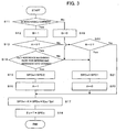
- FIG. 3 is a flow chart showing an alternative speed switching process in which whether the machining has come out of the corner portion or not is determined on the basis of machining programs.
- the processor determines whether the corner portion is being machined or not, on the basis of the machining programs (Step S11). If not, the processor sets a flag for indicating that the corner portion is being machined (referred to as "corner portion machining flag") B to "0" (Step S19), sets the reference feed speed SPDs to the normal machining set feed speed SPD1 (Step S21), sets the corner portion control flag A to "0", and goes to Step S17.
- the processor calculates the feed speed SPDx according equation (12), and then obtains the motion amount ⁇ x by multiplying the feed speed SPDx and the unit time (predetermined period) T and supplies the motion amount ⁇ x to the feed pulse distribution unit 12 (Step S18).
- Step S12 When the processor determines that the corner portion is being machined, on the basis of the machining programs, the processor sets the corner portion machining flag B to "1" (Step S12), and determines whether the corner portion control flag A is "0" or not (Step S13). Since the corner portion control flag A has been initially set to "0", the processor goes to Step S14, where the processor determines whether or not the average drop voltage value Ex is greater than the reference machining rate for determining entrance into corner (Step S14). If the average drop voltage value Ex is smaller, the processor goes to Step S21, and performs Steps S21, S22, S17 and S18.
- Step S15 the processor sets the reference feed speed SPDs to the corner portion machining set feed speed SPD2 (Step S15), sets the corner portion control flag A to "1" and goes to Step S17.
- Step S17 the processor calculates the feed speed SPDx according to equation (12), and then obtains the motion amount ⁇ x by multiplying the feed speed SPDx and the unit time (predetermined period) T and supplies the motion amount ⁇ x to the feed pulse distribution unit 12 (Step S18).
- Step S13 the processor determines whether the corner portion machining flag B is "0" or not. Since the flag B has been set to "1" in Step S12, the processor goes from Step S20 to Step S17, where the feed speed SPDx is obtained using the reference feed speed SPDs which has been already set to the corner machining set feed speed SPD2 in Step S15. After this, a series of Steps S11, S12, S13, S20, S17 and S18 is performed repeatedly, so that the feed control according to the corner portion control curve in FIG. 13 is performed.
- Step S11 When the machining further proceeds and the processor determines, on the basis of the machining programs, that the machining has come out of the corner portion, the processor goes from Step S11 to Step 19, where the processor sets the corner portion machining flag B to "0". Then the processor sets the reference feed speed SPDs to the normal machining set feed speed SPD1 (Step S21), sets the corner control flag A to "0" (Step S22) and goes to Step S17, to thereby return to the feed control according to the normal control curve in FIG. 13.
- the rate of machining is identified on the basis of the drop of the gap voltage, namely the voltage across the gap between the wire electrode 4 and the workpiece 5.
- the rate of machining may be identified on the basis of the number of repetitions of electric discharge which is detected from, for example, the gap voltage, in which case, the same result can be obtained using equation (5).
- the discharge gap detection unit 6 shown in FIG. 1 comprises means for detecting electric discharges
- the machining rate detection unit 7 comprises electric discharge repetition number count means for obtaining the number of repetitions of electric discharge Fx, namely the number of times that electric discharges are produced in the unit time T.
- the reference machining rate storage unit 8 is means for storing the number of repetitions of electric discharge Fs corresponding to the reference rate of machining, and the comparison/determination unit 9 comprises means for obtaining the ratio (Fs/Fe) between the numbers of repetitions of electric discharge Fs and Fx.
- Steps S1 to S9 correspond to Steps S1' to S9', and that the only difference is Steps S2' S7' and S5' which replace Steps S2, S7 and S5.
- Step S2' it is determined whether or not the number of repetitions of electric discharge Fx in the predetermined period T is greater than the reference machining rate for determining entrance into corner (number of repetition of electric discharges).
- Step S7' it is determined whether or not the number of repetitions of electric discharge Fx in the predetermined period T is smaller than the reference machining rate for determining leaving from corner (number of repetition of electric discharges).
- Step S5' the feed speed SPDx is calculated according to equation (5), or in other words, the feed speed SPDx is obtained by multiplying the proportionality constant K, the reference feed speed SPDs set in Step S3' or S8', and the ratio (Fs/Fx) between the reference number of repetitions of electric discharge Fs and the number of detected repetitions of electric discharge Fx.
- Step S11 to S22 in FIG. 3 correspond to Steps S11' to S22' in FIG. 5.
- Step S14' which replaces Step S14, it is determined whether or not the number of repetitions of electric discharge Fx in the predetermined period T is greater than the reference machining rate (number of repetitions of electric discharge) for determining entrance into corner; and in Step S17' which replaces Step S17, the feed speed SPDx is calculated according to equation (5) using the ratio (Fs/Fx) between the numbers of repetitions of electric discharge.
- the process is the same as that shown in FIG. 3. Hence, the detailed explanation thereof will be omitted.
- the set feed speed switching unit 19 changes the reference feed speed SPDs when it is found that the drop voltage value Ex or the number of repetitions of electric discharge Fx has exceeded the entrance-into-corner determination reference machining rate (see Steps S2, S14, S2' and S14') and when it is found that the drop voltage value Ex or the number of repetitions of electric discharge Fx has become smaller than the reference machining rate for determining leaving from corner (see Steps S7, S7').
- the reference feed speed SPDs may be changed on the basis of the ratio (Es/Ex) between the drop voltage values or the ratio (Fs/Fx) between the numbers of repetitions of electric discharge.
- decrease in the ratio (Es/Ex) or the ratio (Fs/Fx) means increase in the drop voltage value Ex or the number of repetitions of electric discharge Fx, and hence, increase in the size of the part that remains to be removed.
- increase in the ratio (Es/Ex) or the ratio (Fs/Fx) means decrease in the drop voltage value Ex or the number of repetitions of electric discharge Fx, and hence, decrease in the size of the part that remains to be removed.
- the feed speed switching can be arranged such that the reference feed speed SPDs is set to the corner set feed speed SPD2 when the ratio (Es/Ex) or the ratio (Fs/Fx) decreases to below a first reference ratio, and set to the normal set feed speed SPD1 when the ratio (Es/Ex) or the ratio (Fs/Fx) increases to above a second reference ratio.
Landscapes
- Chemical & Material Sciences (AREA)
- Chemical Kinetics & Catalysis (AREA)
- Electrochemistry (AREA)
- Engineering & Computer Science (AREA)
- Mechanical Engineering (AREA)
- Electrical Discharge Machining, Electrochemical Machining, And Combined Machining (AREA)
Applications Claiming Priority (1)
| Application Number | Priority Date | Filing Date | Title |
|---|---|---|---|
| JP2004313911A JP4015148B2 (ja) | 2004-10-28 | 2004-10-28 | ワイヤ放電加工機の制御装置 |
Publications (3)
| Publication Number | Publication Date |
|---|---|
| EP1652610A2 true EP1652610A2 (de) | 2006-05-03 |
| EP1652610A3 EP1652610A3 (de) | 2010-01-27 |
| EP1652610B1 EP1652610B1 (de) | 2013-03-06 |
Family
ID=35883813
Family Applications (1)
| Application Number | Title | Priority Date | Filing Date |
|---|---|---|---|
| EP05256569A Ceased EP1652610B1 (de) | 2004-10-28 | 2005-10-24 | Steuerung für Drahtschneidefunkenerosionsmaschine |
Country Status (4)
| Country | Link |
|---|---|
| US (1) | US7262381B2 (de) |
| EP (1) | EP1652610B1 (de) |
| JP (1) | JP4015148B2 (de) |
| CN (1) | CN1765555B (de) |
Cited By (1)
| Publication number | Priority date | Publication date | Assignee | Title |
|---|---|---|---|---|
| US20200290142A1 (en) * | 2019-03-12 | 2020-09-17 | Fanuc Corporation | Wire electrical discharge machine and wire electrical discharge machining method |
Families Citing this family (27)
| Publication number | Priority date | Publication date | Assignee | Title |
|---|---|---|---|---|
| US7528340B2 (en) * | 2006-07-24 | 2009-05-05 | Sodick Co., Ltd. | Apparatus and method for electric discharge machining and method of discriminating electric discharge |
| ATE517705T1 (de) * | 2007-06-30 | 2011-08-15 | Trumpf Werkzeugmaschinen Gmbh | Werkzeugmaschine und verfahren zum ausschleusen eines werkstückteils |
| US8829383B2 (en) | 2008-07-03 | 2014-09-09 | Mitsubishi Electric Corporation | Wire electric discharge machine and wire electric discharge machining method |
| US8642915B2 (en) * | 2008-10-29 | 2014-02-04 | Mitsubishi Electric Corporation | Wire electric discharge machining apparatus |
| JP4970476B2 (ja) * | 2009-01-30 | 2012-07-04 | 株式会社ソディック | ワイヤカット放電加工装置 |
| WO2011004426A1 (ja) * | 2009-07-07 | 2011-01-13 | 三菱電機株式会社 | ワイヤ放電加工装置 |
| JP4734447B2 (ja) * | 2009-11-26 | 2011-07-27 | ファナック株式会社 | ワイヤカット放電加工機および放電加工方法 |
| US20130062318A1 (en) * | 2010-05-21 | 2013-03-14 | Mitsubishi Electric Corporation | Wire discharge machine |
| CN102179583A (zh) * | 2011-04-28 | 2011-09-14 | 泰德兴精密电子(昆山)有限公司 | 改进的慢丝尖角加工工艺 |
| JP5166586B1 (ja) * | 2011-10-13 | 2013-03-21 | ファナック株式会社 | 加工状態に基づき加工液量を調節するワイヤ放電加工機 |
| US9399260B2 (en) | 2012-01-11 | 2016-07-26 | Mitsubishi Electric Corporation | Wire electrical discharge machining apparatus |
| JP5204321B1 (ja) * | 2012-02-01 | 2013-06-05 | ファナック株式会社 | 加工状態を検出し極間の平均電圧を求めるワイヤ放電加工機 |
| JP5270772B1 (ja) * | 2012-02-15 | 2013-08-21 | ファナック株式会社 | 歪み取り加工を行うワイヤ放電加工機 |
| JP5689431B2 (ja) * | 2012-03-12 | 2015-03-25 | ファナック株式会社 | プログラム指令によって加工経路の補正を行うワイヤ放電加工機の制御装置 |
| JP5426733B2 (ja) * | 2012-07-10 | 2014-02-26 | ファナック株式会社 | ワイヤ放電加工機およびワイヤ放電加工機用自動プログラミング装置 |
| JP5722290B2 (ja) * | 2012-09-20 | 2015-05-20 | ファナック株式会社 | 軸送り制御方式判別機能を有するワイヤ放電加工機 |
| CN104853872B (zh) | 2013-12-10 | 2017-07-14 | 三菱电机株式会社 | 线电极放电加工装置、线电极放电加工方法以及控制装置 |
| CN103658891B (zh) * | 2013-12-28 | 2015-08-12 | 哈尔滨工业大学 | 数控电火花线切割机床在放电过程中的长短路抑制装置 |
| JP6219785B2 (ja) * | 2014-06-23 | 2017-10-25 | ファナック株式会社 | 断線修復手段を備えたワイヤ放電加工機 |
| JP2017113825A (ja) * | 2015-12-22 | 2017-06-29 | ファナック株式会社 | ワイヤ放電加工機 |
| CN105643030B (zh) * | 2016-03-01 | 2017-11-03 | 上海交通大学 | 一种用于多轴联动电火花加工的进给速度后处理器设计方法 |
| CN106112151B (zh) * | 2016-07-29 | 2018-02-06 | 佛山科学技术学院 | 旋转电火花加工伺服方法及系统 |
| CN106270847A (zh) * | 2016-08-31 | 2017-01-04 | 深圳天珑无线科技有限公司 | 一种线切割方法 |
| JP6360212B1 (ja) * | 2017-01-31 | 2018-07-18 | ファナック株式会社 | ワイヤ放電加工機 |
| JP6506349B2 (ja) * | 2017-06-19 | 2019-04-24 | ファナック株式会社 | ワイヤ放電加工機の制御装置、および、ワイヤ放電加工機の制御方法 |
| JP7372191B2 (ja) * | 2019-11-08 | 2023-10-31 | ファナック株式会社 | プログラム編集装置、ワイヤ放電加工機およびプログラム編集方法 |
| WO2022269847A1 (ja) * | 2021-06-24 | 2022-12-29 | ファナック株式会社 | ワイヤ放電加工機、及び、ワイヤ放電加工機の制御方法 |
Citations (4)
| Publication number | Priority date | Publication date | Assignee | Title |
|---|---|---|---|---|
| WO1988003071A1 (en) | 1986-10-24 | 1988-05-05 | Mitsubishi Denki Kabushiki Kaisha | Wire cut electrical discharge machine |
| US20030098293A1 (en) | 2001-11-29 | 2003-05-29 | Mitsubishi Denki Kabushiki Kaisha | Wire electric-discharge machining apparatus |
| EP1462202A1 (de) | 2003-03-24 | 2004-09-29 | Fanuc Ltd | Steuerung für Drahtfunkenerosionsbearbeitungsmaschine |
| EP1607161A1 (de) | 2004-06-02 | 2005-12-21 | Fanuc Ltd | Steuerung für eine Drahtschneidefunkenerosionsbearbeitungsmaschine |
Family Cites Families (4)
| Publication number | Priority date | Publication date | Assignee | Title |
|---|---|---|---|---|
| JP2818429B2 (ja) * | 1989-02-01 | 1998-10-30 | 株式会社アマダ | ワイヤ放電加工機におけるコーナ制御方法 |
| JP3566988B2 (ja) * | 1994-07-27 | 2004-09-15 | ファナック株式会社 | ワイヤ放電加工方法 |
| JP3231567B2 (ja) | 1994-12-07 | 2001-11-26 | 株式会社ソディック | ワイヤ放電加工方法 |
| JP4056638B2 (ja) * | 1998-09-08 | 2008-03-05 | 株式会社ソディック | ワイヤカット放電加工方法及びワイヤカット放電加工装置 |
-
2004
- 2004-10-28 JP JP2004313911A patent/JP4015148B2/ja not_active Expired - Fee Related
-
2005
- 2005-10-24 EP EP05256569A patent/EP1652610B1/de not_active Ceased
- 2005-10-27 US US11/258,950 patent/US7262381B2/en not_active Expired - Lifetime
- 2005-10-28 CN CN200510116957.3A patent/CN1765555B/zh not_active Expired - Fee Related
Patent Citations (4)
| Publication number | Priority date | Publication date | Assignee | Title |
|---|---|---|---|---|
| WO1988003071A1 (en) | 1986-10-24 | 1988-05-05 | Mitsubishi Denki Kabushiki Kaisha | Wire cut electrical discharge machine |
| US20030098293A1 (en) | 2001-11-29 | 2003-05-29 | Mitsubishi Denki Kabushiki Kaisha | Wire electric-discharge machining apparatus |
| EP1462202A1 (de) | 2003-03-24 | 2004-09-29 | Fanuc Ltd | Steuerung für Drahtfunkenerosionsbearbeitungsmaschine |
| EP1607161A1 (de) | 2004-06-02 | 2005-12-21 | Fanuc Ltd | Steuerung für eine Drahtschneidefunkenerosionsbearbeitungsmaschine |
Cited By (2)
| Publication number | Priority date | Publication date | Assignee | Title |
|---|---|---|---|---|
| US20200290142A1 (en) * | 2019-03-12 | 2020-09-17 | Fanuc Corporation | Wire electrical discharge machine and wire electrical discharge machining method |
| US11724324B2 (en) * | 2019-03-12 | 2023-08-15 | Fanuc Corporation | Wire electrical discharge machine and wire electrical discharge machining method |
Also Published As
| Publication number | Publication date |
|---|---|
| EP1652610A3 (de) | 2010-01-27 |
| US20060091113A1 (en) | 2006-05-04 |
| EP1652610B1 (de) | 2013-03-06 |
| JP2006123065A (ja) | 2006-05-18 |
| JP4015148B2 (ja) | 2007-11-28 |
| US7262381B2 (en) | 2007-08-28 |
| CN1765555B (zh) | 2010-05-05 |
| CN1765555A (zh) | 2006-05-03 |
Similar Documents
| Publication | Publication Date | Title |
|---|---|---|
| EP1652610B1 (de) | Steuerung für Drahtschneidefunkenerosionsmaschine | |
| EP2018923B1 (de) | Steuerung für eine elektrische Drahterodiermaschine | |
| EP2272613B1 (de) | Elektrische Drahterodiermaschine mit Funktion zur Unterdrückung der lokalen Bildung von Streifen während der Endbearbeitung | |
| EP1849547B1 (de) | Steuerung für eine elektrische Drahterodiermaschine | |
| EP2272614B1 (de) | Steuerung für eine elektrische Drahterodiermaschine | |
| EP2617506B1 (de) | Drahterodiermaschine, die eine elektrische Drahterodierbearbeitung durch eine sich neigende Drahtelektrode ausführt | |
| EP1319459B1 (de) | Drahtfunkenerosionsbearbeitung | |
| JP2002254250A (ja) | ワイヤ放電加工機の制御装置 | |
| EP0134679B1 (de) | Verfahren und Apparat zum elektroerosiven Bearbeiten | |
| JP4569973B2 (ja) | 放電加工装置及び方法、並びに放電発生を判別する方法 | |
| EP0343255B1 (de) | Verfahren zum nachweis der arbeitsbedingungen einer drahtfunkenerosionsvorrichtung | |
| EP3235584B1 (de) | Drahterosionsbearbeitungsvorrichtung und -verfahren | |
| KR0158285B1 (ko) | 방전가공방법 및 장치 | |
| JP4689479B2 (ja) | ワイヤ放電加工機の制御装置 | |
| JP2006110721A (ja) | ワイヤ放電加工機の制御装置 | |
| EP1410865A2 (de) | Funkenerosionsmaschine |
Legal Events
| Date | Code | Title | Description |
|---|---|---|---|
| PUAI | Public reference made under article 153(3) epc to a published international application that has entered the european phase |
Free format text: ORIGINAL CODE: 0009012 |
|
| AK | Designated contracting states |
Kind code of ref document: A2 Designated state(s): AT BE BG CH CY CZ DE DK EE ES FI FR GB GR HU IE IS IT LI LT LU LV MC NL PL PT RO SE SI SK TR |
|
| AX | Request for extension of the european patent |
Extension state: AL BA HR MK YU |
|
| PUAL | Search report despatched |
Free format text: ORIGINAL CODE: 0009013 |
|
| AK | Designated contracting states |
Kind code of ref document: A3 Designated state(s): AT BE BG CH CY CZ DE DK EE ES FI FR GB GR HU IE IS IT LI LT LU LV MC NL PL PT RO SE SI SK TR |
|
| AX | Request for extension of the european patent |
Extension state: AL BA HR MK YU |
|
| 17P | Request for examination filed |
Effective date: 20100329 |
|
| 17Q | First examination report despatched |
Effective date: 20100525 |
|
| AKX | Designation fees paid |
Designated state(s): CH LI |
|
| REG | Reference to a national code |
Ref country code: DE Ref legal event code: 8566 |
|
| RAP1 | Party data changed (applicant data changed or rights of an application transferred) |
Owner name: FANUC CORPORATION |
|
| GRAP | Despatch of communication of intention to grant a patent |
Free format text: ORIGINAL CODE: EPIDOSNIGR1 |
|
| GRAS | Grant fee paid |
Free format text: ORIGINAL CODE: EPIDOSNIGR3 |
|
| GRAA | (expected) grant |
Free format text: ORIGINAL CODE: 0009210 |
|
| AK | Designated contracting states |
Kind code of ref document: B1 Designated state(s): CH LI |
|
| REG | Reference to a national code |
Ref country code: CH Ref legal event code: EP Ref country code: CH Ref legal event code: NV Representative=s name: DR. LUSUARDI AG, CH |
|
| PLBE | No opposition filed within time limit |
Free format text: ORIGINAL CODE: 0009261 |
|
| STAA | Information on the status of an ep patent application or granted ep patent |
Free format text: STATUS: NO OPPOSITION FILED WITHIN TIME LIMIT |
|
| 26N | No opposition filed |
Effective date: 20131209 |
|
| PGFP | Annual fee paid to national office [announced via postgrant information from national office to epo] |
Ref country code: CH Payment date: 20191015 Year of fee payment: 15 |
|
| REG | Reference to a national code |
Ref country code: CH Ref legal event code: PL |
|
| PG25 | Lapsed in a contracting state [announced via postgrant information from national office to epo] |
Ref country code: LI Free format text: LAPSE BECAUSE OF NON-PAYMENT OF DUE FEES Effective date: 20201031 Ref country code: CH Free format text: LAPSE BECAUSE OF NON-PAYMENT OF DUE FEES Effective date: 20201031 |