EP1652625A2 - Sperr- und Tiefeneinstellvorrichtung für Setzgeräte - Google Patents
Sperr- und Tiefeneinstellvorrichtung für Setzgeräte Download PDFInfo
- Publication number
- EP1652625A2 EP1652625A2 EP05023609A EP05023609A EP1652625A2 EP 1652625 A2 EP1652625 A2 EP 1652625A2 EP 05023609 A EP05023609 A EP 05023609A EP 05023609 A EP05023609 A EP 05023609A EP 1652625 A2 EP1652625 A2 EP 1652625A2
- Authority
- EP
- European Patent Office
- Prior art keywords
- fastening tool
- trigger
- trip mechanism
- contact trip
- trigger switch
- Prior art date
- Legal status (The legal status is an assumption and is not a legal conclusion. Google has not performed a legal analysis and makes no representation as to the accuracy of the status listed.)
- Withdrawn
Links
Images







Classifications
-
- B—PERFORMING OPERATIONS; TRANSPORTING
- B25—HAND TOOLS; PORTABLE POWER-DRIVEN TOOLS; MANIPULATORS
- B25C—HAND-HELD NAILING OR STAPLING TOOLS; MANUALLY OPERATED PORTABLE STAPLING TOOLS
- B25C1/00—Hand-held nailing tools; Nail feeding devices
- B25C1/008—Safety devices
Definitions
- the present invention relates to a cordless fastening tool and more specifically to a depth adjustment mechanism and an operational lock.
- Traditional fastening tools can employ pneumatic actuation to drive a fastener into a work-piece.
- air pressure from a pneumatic system can be utilized to both drive the fastener into the work-piece and to reset the tool after driving the fastener.
- a hose and a compressor are required to accompany the tool.
- a combination of the hose, the tool and the compressor provides for a large, heavy and bulky package that is relatively inconvenient and cumbersome to transport.
- One alternative to a tool that requires a pneumatic system are tools that employ combustion systems for generating power to drive a fastener into a work-piece. These tools typically hold a combustible propellant and have a battery that is employed to produce a spark for igniting the combustible propellant. Expanding combustion gases are used to drive the fastener. Additional propellant canisters, therefore, must be carried to ensure continued use of the fastening tool. Moreover, the combustion system can exhaust combustion gases in close proximity to the user.
- a fastening tool including a contact trip mechanism having a trigger block.
- the contact trip mechanism is moveable to a retracted position.
- the fastening tool also includes a slider member connected to the trigger block and a link member adjustably coupled to the slider member,
- the fastening tool further includes a lockout pin movable between a first position and a second position. The lockout pin in the first position decouples the slider member and the link member and holds the trigger block in a blocked position.
- the fastening tool 10 can include an exterior housing 12, which can house a motor 14, a transmission 16, a driver mechanism 18 and a control module 20.
- the fastening tool 10 can also include a nosepiece 22 and a fastener magazine 24 and a battery 26.
- the fastener magazine 24 can be coupled to the driver mechanism 18, while the battery 26 can be coupled to the exterior housing 12.
- the motor 14 can drive the transmission 16, which in turn can actuate the driver mechanism 18.
- Actuation of the driver mechanism 18 can drive fasteners 28, which are sequentially fed from the fastener magazine 24 into the nosepiece 22, into a work-piece 30.
- the fasteners 28 could be nails, staples, brads, clips or any such suitable fastener that could be driven into the work-piece 30.
- a driveshaft 32 can connect an input (not specifically shown) of the transmission 16 to an output (not specifically shown) of the motor 14.
- a transmission housing 34 can encase the transmission 16, a portion of a driveshaft 32 and various components of the transmission 16.
- a driveshaft bearing 36 can be employed to joumally support the driveshaft 32 in the transmission housing 34.
- the transmission 16 can indude a first drive gear 38 and a second drive gear 40 that can be coupled for rotation with the driveshaft 32 within the transmission housing 34.
- the first drive gear 38 can be closer to the motor 14 relative to the second drive gear 40. It will be appreciated that the driveshaft 32, the first drive gear 38 and the second drive gear 40 can rotate at the same rotational speed.
- the transmission 16 can also include a flywheel 42 and a cam gear 44 that can be mounted for rotation on a transmission shaft 46.
- the first drive gear 38 can meshingly engage and drive the flywheel 42 while the second drive gear 40 can meshingly engage and drive the cam gear 44.
- the flywheel 42, the cam gear 44, the first drive gear 38 and the second drive gear 40 can form a transmission gear set 48.
- each gear of the transmission gear set 48 can be configured (e.g., by pitch diameter and/or by number of teeth) so that the flywheel 42 and the cam gear 44 rotate at different rotational speeds.
- the flywheel 42 for example, can rotate in response to rotation of the driveshaft 32 at a faster rotational velocity than the cam gear 44.
- the cam gear 44 can include a cover 50 defining a ramp 52.
- the cover 50 can fixedly connect to the cam gear 44 opposite the flywheel 42.
- the flywheel 42 can include a dutch arm 54 that can rotate with the remainder of the flywheel 42.
- the clutch arm 54 can be disposed on a side of the ramp 52 opposite the cam gear 44.
- the ramp 52 can be configured to engage a clutch pin 56 that is carried by the clutch arm 54, as shown in Figure 7.
- rotation of the cam gear 44 at a rotational velocity that is less than that of the flywheel 42 can cause a head 58 of the dutch pin 56 to advance toward or approach the ramp 52, as is illustrated in Figures 5 and 7.
- a clutch pin spring 60 can bias the dutch pin 56 into a retracted or a seated position 62, which is shown in Figure 5. Contact between the ramp 52 and the clutch pin 56 can cause the clutch pin 56 to travel up the ramp 52 and push the clutch pin 56 outwardly from the dutch arm 54 from the seated position 62 into an extended position 64, as shown in Figure 7.
- the clutch pin 56 when the clutch pin 56 is in the extended position 64, the clutch pin 56 can extend above a face 66 of the clutch arm 54 in a direction opposite the cover 50. In the seated position 62, the clutch pin 56 can extend below an opposite dutch arm face 68, which can be adjacent to the cover 50. It will also be appreciated that the clutch arm 54 can be counter-balanced such that the clutch pin 56 is radially spaced apart from a center of the transmission shaft 46. The opposite side of the clutch arm 54, which can counter-balance the clutch pin 56 with a suitable weight 70, is distal from the dutch pin 56.
- the ramp 52 pushes the clutch pin 56 into the extended position 64, as shown in Figure 7.
- the clutch pin 56 engages the driver mechanism 18. It will be appreciated that the extended position 64 can coincide with placement of the dutch pin 56 along any part of the ramp 52 that permits the clutch pin 56 to extend from the clutch arm 54 by a distance that is sufficient to engage the driver mechanism 18.
- the driver mechanism 18 includes a driver blade 72 that connects to a crank link 74.
- the crank link 74 indudes a crank link cam 76 ( Figure 3).
- the driver mechanism 18 also includes a crank link return-spring 78 ( Figure 3) that can connect to the crank link cam 76.
- the dutch pin 56 can engage the crank link 74 at a pin catch 80 ( Figure 4) and can drive the crank link 74 from a first position 82 to a second position 84.
- the motion of the crank link 74 moves the driver blade 72 from a top position 86 to a bottom position 88.
- the driver blade 72 can insert (i.e., drive) the fastener 28 into the work-piece 30 ( Figure 1) as it travels to the bottom position 88.
- crank link return-spring 78 ( Figure 3) can return the crank link 74 to the first position 82, as shown in Figure 6.
- the crank link cam 76 can be disposed in a link track 90 on the transmission housing 34.
- the crank link return-spring 78 can urge (bias) the crank link cam 76 along the link track 90 toward the first position 82.
- the driver sequence can indude the clutch pin 56 engaging the pin catch 80 and driving the crank link 74; the driver blade 72 translating from the first and top positions 82, 86 to the second and bottom positions 84, 88; the clutch pin 56 disengaging the pin catch 80; and the crank link returnspring 78 urging the crank link cam 76 upwardly in the link track 90 to cause the crank link 74 and the driver blade 72 to return to the first and top positions 82, 86, which can complete the driver sequence.
- crank link 74 can be configured such that travel beyond the second position 84 can be limited by, for example, one or more resilient bumpers 92.
- the dutch pin 56 ( Figure 5), therefore, can disengage from the crank link 74 at the bottom position 88.
- a link joint 94 can pivotally connect the crank link 74 and the driver blade 72.
- the link joint 94 can allow the crank link 74 to travel in an approximately circular path, while the driver blade 72 travels in a vertical path (i.e., up and down).
- a blade channel 96 can be employed to confine the driver blade 72 for movement along a desired axis to ensure travel in an up and down direction.
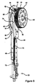
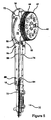
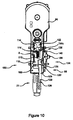
- the nosepiece 22 can include a contact trip mechanism 98 that is movable between a retracted position 100, which is illustrated in Figure 10, and an extended position 102, which is illustrated in Figure 11.
- the contact trip mechanism 98 can be configured to prevent the fastening tool 10 from executing the driver sequence unless the contact trip mechanism 98 is in the retracted position 100 ( Figure 10) (e.g., pressed against the work-piece 30).
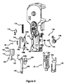
- the contact trip mechanism 98 can include a multi-component mechanical linkage that can connect the nosepiece 22 to a trigger assembly 104 ( Figure 2).
- the contact trip mechanism 98 can include a contact member 106 that connects to a nosepiece 22.
- the contact member 106 can connect to a link member 108.
- the link member 108 can connect to a slider member 110.
- the slider member 110 can connect to a carrier member 112.
- the carrier member 112 can connect to a trigger block 114.
- the carrier member 112 can also connect to a contact trip spring 116.
- the carrier member 112 and the contact trip spring 116 can connect to a carrier depression 118 formed in the transmission housing 34.
- the contact member 106 when the contact member 106 is pushed against the work-piece 30, the contact member 106 moves up (i.e., toward the flywheel 42). When the contact member 106 moves up, the contact trip mechanism 98 can move into the retracted position 100. In the retracted position 100, the trigger block 114 can pivot from a blocked position 120 to an unblocked position 122.
- the contact member 106 can include an adjusting lever 124 and a nose-link portion 126 that can extend approximately orthogonally to a remainder of the contact member 106.
- the nose-link portion 126 can fit into a nose-link aperture 128 formed on the link member 108.
- the link member 108 can further includes a pin 129a that can extend through the link member 108 and into a slot 129b formed in the carrier member 112.
- the link member 108 can also include a plurality of teeth 130 that are distal from the nose-link aperture 128.
- the plurality of teeth 130 on the link member 108 can engage with a plurality of teeth 132 on the slider member 110.
- a slider pin 133a can be employed to pivotally couple the slider member 110 to the carrier member 112.
- the slider pin 133a is fixedly coupled to the slider member 110 and rotatably disposed in a slider pin aperture 133b in the carrier member 112.
- the plurality of teeth 130 formed on the link member 108 can be disposed within the carrier depression 118 formed on the transmission housing 34.
- a depth adjustment assembly 134 can be employed to control the depth at which the fastener 28 is driven into the work-piece 30 (e.g., counter-sink or flush),
- the depth adjustment assembly 134 can include two sets of mating teeth that can be employed to set and selectively change the effective length of the contact trip mechanism 98 as desired.
- the plurality of teeth 130 of the link member 108 can be selectively engaged to the plurality of teeth 132 of the slider member 110.
- the pluralities of teeth 130,132 can be disengaged and then can be reengaged at a different location to change the effective length of the contact trip mechanism 98.
- the user can control the depth that the fastening tool 10 drives the fastener 28 into the work-piece 30.
- the depth adjustment assembly 134 can also include a depth adjustment actuator mechanism 136.
- the actuator mechanism 136 can include an actuator button 138 that can be hinged via an assembly pin 140 to the transmission housing 34.
- An actuator pin 142 can be disposed in an actuator spring 144 and can be connected to the actuator button 138.
- the user can press the actuator button 138 to push the actuator pin 142 against the bias of the actuator spring 144 and into contact with the slider member 110.
- Sufficient movement of the slider member 110 away from the link member 108 can disengage the slider member 110 from the link member 108.
- the pin 129a on the link member 108 which is disposed in the groove 129b on the carrier member 112, can restrain the link member 108 and thereby prevent the link member 108 from moving with the slider member 110.
- the slider member 110 can pivot away from the link member 108 in a clockwise fashion upon the slider pin 133a, as generally indicated by reference numeral 146a.
- the plurality of teeth 132 on the slider member 110 can disengage from the plurality of teeth 130 on the link member 108.
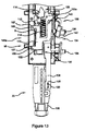
- the link member 108 can be disengaged from the slider member 110 and the user can move the adjusting lever 124 of the link member 108 up and/or down (as illustrated in Figure 13) to decrease and/or increase, respectively, the effective length of the contact trip mechanism 98.
- the depth adjustment assembly 134 may be alternatively configured so as to omit the slider pin 133a ( Figure 12a). In that configuration, the slider member 110 can translate away from the link member 108 in a horizontal fashion (i.e., right to left in Figure 12b), as generally indicated by reference numeral 146b.
- the fastening tool 10 can be configured to drive the fastener 28 into the work-piece 30 such that a head 148 (Figure 1) of the fastener, for example, will sit flush with the work-piece 30, which is generally indicated by reference numeral 150.
- the depth adjustment assembly 134 can also be adjusted such that the head 148 of the fastener 28 can be sunk into (i.e., below the surface of) the work-piece 30, which is generally indicated by reference numeral 152 ( Figure 1). It will be appreciated that when the head 148 of the fastener 28 is counter-sunk the head 148 is disposed below a surface 154 of the work-piece 30.
- the actuator pin 142 can also be employed to restrain movement of the carrier member 112.
- the actuator pin 142 can push the slider member 110 such that protrusions 155 formed on the slider member 110 can be inserted through recesses 156 ( Figure 9) on the carrier member 112 and into slots 157 that can be formed into the transmission housing 34 and which intersect the carrier depression 118.
- the contact trip mechanism 98 is held in the extended position 102 ( Figure 11) and also prevented from moving into the retracted position 100 ( Figure 10).
- the contact trip mechanism 98 when the contact trip mechanism 98 is held in the extended position 102, the fastening tool 10 will not be able to execute the driver sequence. It will also be appreciated that the contact trip mechanism 98 illustrated and described herein is held in the extended position 102 while the user adjusts the effective length of the contact trip mechanism 98.
- a spring S ( Figure 9), such as a leaf spring, may be employed to urge the slider member 110 toward the link member 108 so that the plurality of teeth 130 on the slider member 110 can reengage with the plurality of teeth 130 on the link member 108.
- the trigger assembly 104 can mount to the transmission housing 34 and extend through the exterior housing 12.
- the trigger assembly 104 can include a trigger 158 that can be biased into an extended position 160 ( Figure 1).
- the user can move (i.e., pivot and/or translate) the trigger 158 into an activated position 162 ( Figure 2).
- the trigger 158 can activate a trigger switch 164.
- a trigger actuation member 166 can be employed to couple the trigger 158 to the trigger switch 164 and can cause the trigger switch 164 to generate a trigger signal (not shown).
- the fastening tool 10 can execute the driver sequence.
- Electronic control of the fastening tool 10 and the communication to and/or from the control module 20 e.g., transmission and receipt of the trigger signal
- the control module 20 e.g., transmission and receipt of the trigger signal
- the fastening tool 10 can have an operational lockout mechanism 168 that can also inhibit the fastening tool 10 from executing the driver sequence.
- the operational lockout mechanism 168 can include a lockout switch 170 (Figure 1) that can be connected to an actuator catch 172.
- the lockout switch 170 can be mounted to the exterior housing 12 and can be coupled to the lockout catch 172.
- the lockout switch 170 and the lockout catch 172 can move between a lockout position 174, which is illustrated in Figures 15 and 16, and an operational position 176, which is illustrated in Figures 17 and 18.
- the actuator catch 172 can include an aperture 177 through which a catch pin 178 formed in the transmission housing 34 is disposed to pivotally connect to the lockout catch 172 to the transmission housing 34.
- the actuator catch 172 can include a second catch pin 179 that can couple the actuator catch 172 with the actuator switch 170.
- the lockout catch 172 can hold the trigger actuation member 166 away from the trigger switch 164. More specifically, when the trigger actuation member 166 is urged toward the trigger switch 164, a portion of the lockout catch 172, such as an arm 180 lockout, can be configured to urge the trigger actuation member 166 away from the trigger switch 164, as shown in Figure 16. In the example provided, a sloping surface 180a of the arm 180 deflects the trigger actuation member 166 away from a trigger switch actuator 184 as the trigger 158 ( Figure 1) urges the trigger actuation member 166 toward the trigger switch 164.
- the actuator catch 172 does not inhibit movement of the trigger actuator member 166.
- the arm 180 can be configured so as not to block the trigger actuation member 166 when it is urged by the trigger 158 ( Figure 1) toward the trigger switch actuator 184.
- the trigger block 114 of the contact trip mechanism 98 ( Figure 9) can additionally block the trigger actuation member 166 from contacting the trigger switch 164 in the example provided, as when the contact trip mechanism 98 ( Figure 9) is in the extended position.
- the operation lockout mechanism 168 ( Figure 1) is in the operational position 176, and trigger block 114 is in the unblocked position 122.
- trigger 158 ( Figure 1) may be employed to move the trigger actuation member 166 into contact with the trigger switch actuator 184 to actuate the trigger switch 164 and execute the driver sequence.
- the lockout switch 170 ( Figure 1) is in the lockout position 174 ( Figure 15)
- the trigger actuation member 166 is prevented from contacting the higger switch actuator 184 and as such, the fastening tool cannot be activated even when the trigger 158 ( Figure 1) is positioned in the activated position 162 ( Figure 2) and the contact trip mechanism 98 is moved to the retracted position 100 ( Figure 10).
- the lockout switch 170 ( Figure 1) can completely prevent operation of the fastening tool 10 ( Figure 1) when placed in the lockout position 174 ( Figure 15).
- the trigger switch 164 can be any suitable type of switch including, but not limited to, a micro switch.
- the trigger switch 164 can include a trigger switch body 182 and the trigger switch actuator 184. It can be appreciated that the trigger actuation member 166 can contact the trigger switch body 182 and that this contact does not operate to activate the trigger switch 164. Rather, actuation of the trigger switch 164 is effected through contact between the trigger actuation member 166 and the trigger switch actuator 184 and/or an actuator lever 186 that can pivot to make contact with the trigger switch actuator.
- the trigger switch 164 illustrated utilizes a translating member for the trigger switch actuator 184
- those of ordinary skill in the art will appreciate that other switch configurations, including those that use a pivoting lever to push a translating member, may be readily substituted for that which is illustrated herein.
- the trigger block 114 can deflect the trigger actuation member 166 from the trigger switch actuator 184 when the trigger block 114 is in the blocked position 120 ( Figure 17) but the trigger actuation member 166 may still contact the trigger switch body 182.
Landscapes
- Engineering & Computer Science (AREA)
- Mechanical Engineering (AREA)
- Portable Nailing Machines And Staplers (AREA)
- Automatic Tool Replacement In Machine Tools (AREA)
Applications Claiming Priority (1)
| Application Number | Priority Date | Filing Date | Title |
|---|---|---|---|
| US10/978,868 US20060091177A1 (en) | 2004-10-29 | 2004-10-29 | Operational lock and depth adjustment for fastening tool |
Publications (2)
| Publication Number | Publication Date |
|---|---|
| EP1652625A2 true EP1652625A2 (de) | 2006-05-03 |
| EP1652625A3 EP1652625A3 (de) | 2010-11-10 |
Family
ID=35462557
Family Applications (1)
| Application Number | Title | Priority Date | Filing Date |
|---|---|---|---|
| EP05023609A Withdrawn EP1652625A3 (de) | 2004-10-29 | 2005-10-28 | Sperr- und Tiefeneinstellvorrichtung für Setzgeräte |
Country Status (6)
| Country | Link |
|---|---|
| US (1) | US20060091177A1 (de) |
| EP (1) | EP1652625A3 (de) |
| CN (1) | CN1775482A (de) |
| AU (1) | AU2005225165A1 (de) |
| CA (1) | CA2524765A1 (de) |
| NZ (2) | NZ543228A (de) |
Families Citing this family (31)
| Publication number | Priority date | Publication date | Assignee | Title |
|---|---|---|---|---|
| TW200600288A (en) * | 2004-02-20 | 2006-01-01 | Black & Decker Inc | Adjustable exhaust system for pneumatic nailers and staplers |
| US7641089B2 (en) * | 2004-04-02 | 2010-01-05 | Black & Decker Inc. | Magazine assembly for nailer |
| US20060091176A1 (en) | 2004-10-29 | 2006-05-04 | Cannaliato Michael F | Cordless fastening tool nosepiece with integrated contact trip and magazine feed |
| US8550324B2 (en) * | 2006-05-23 | 2013-10-08 | Black & Decker Inc. | Depth adjustment for fastening tool |
| JP4664240B2 (ja) * | 2006-06-12 | 2011-04-06 | 株式会社マキタ | 打込み作業工具 |
| US7537145B2 (en) | 2007-02-01 | 2009-05-26 | Black & Decker Inc. | Multistage solenoid fastening device |
| US8931676B2 (en) | 2007-08-27 | 2015-01-13 | Black & Decker Inc. | Nailer having mechanism for pre-positioning nail |
| EP2127817B1 (de) * | 2008-05-30 | 2012-09-12 | Black & Decker, Inc. | Werkzeug zum Antreiben von Befestigungselementen |
| EP2127818B1 (de) * | 2008-05-30 | 2011-04-13 | Black & Decker Inc. | Werkzeug zum Antreiben von Befestigungselementen |
| GB0809868D0 (en) * | 2008-05-30 | 2008-07-09 | Black & Decker Inc | Fastener driving tool |
| US8127974B2 (en) * | 2009-02-25 | 2012-03-06 | Huading Zhang | Electrical motor driven nail gun |
| US8042717B2 (en) * | 2009-04-13 | 2011-10-25 | Stanley Fastening Systems, Lp | Fastener driving device with contact trip having an electrical actuator |
| US8746526B2 (en) * | 2009-09-15 | 2014-06-10 | Robert Bosch Gmbh | Fastener driver with blank fire lockout |
| US8146788B2 (en) * | 2009-12-04 | 2012-04-03 | Robert Bosch Gmbh | Fastening tool with releasable work contact element |
| US9827658B2 (en) | 2012-05-31 | 2017-11-28 | Black & Decker Inc. | Power tool having latched pusher assembly |
| FR2993810B1 (fr) * | 2012-07-25 | 2014-07-11 | Illinois Tool Works | Outil de fixation par tir indirect, a support de detente anti-tir |
| DE102012214694A1 (de) * | 2012-08-17 | 2014-02-20 | Hilti Aktiengesellschaft | Eintreibgerät mit Sicherheitssperre |
| DE102012215126A1 (de) * | 2012-08-24 | 2014-05-28 | Hilti Aktiengesellschaft | Handgeführtes Arbeitsgerät |
| WO2015015967A1 (ja) * | 2013-07-31 | 2015-02-05 | 日立工機株式会社 | 打込機 |
| US12502756B2 (en) | 2013-10-09 | 2025-12-23 | Black & Decker Inc. | High inertia driver system |
| CN107283368B (zh) * | 2016-04-01 | 2021-09-07 | 苏州宝时得电动工具有限公司 | 手持式工具及其操作方法 |
| US20170361443A1 (en) | 2016-06-20 | 2017-12-21 | Black & Decker Inc. | Cylindrical Integrated Valve Assembly |
| US20180093370A1 (en) * | 2016-10-04 | 2018-04-05 | Stanley Black & Decker, Inc. | Fastening Tool with Contact Arm and Multi-Fastener Guide |
| CN108068059B (zh) * | 2016-11-09 | 2022-07-08 | 创科无线普通合伙 | 气弹簧紧固件驱动器的卡塞释放和升降器机构 |
| EP3870403B1 (de) | 2018-10-25 | 2024-03-27 | Milwaukee Electric Tool Corporation | Kraftbetriebenes eintreibgerät mit geteiltem getriebe |
| TWI874386B (zh) * | 2019-06-27 | 2025-03-01 | 日商工機控股股份有限公司 | 釘打機 |
| EP4126461A4 (de) | 2020-03-25 | 2024-09-25 | Milwaukee Electric Tool Corporation | Kraftgetriebener befestigungsmitteltreiber |
| EP4237201A4 (de) | 2020-10-30 | 2024-12-11 | Milwaukee Electric Tool Corporation | Kraftgetriebener befestigungsmitteltreiber |
| US12202112B2 (en) | 2021-01-20 | 2025-01-21 | Milwaukee Electric Tool Corporation | Powered fastener driver |
| WO2022159538A1 (en) * | 2021-01-20 | 2022-07-28 | Milwaukee Electric Tool Corporation | Powered fastener driver |
| US20250353161A1 (en) * | 2024-05-20 | 2025-11-20 | Robert Bosch Gmbh | Fastener driver tool |
Family Cites Families (15)
| Publication number | Priority date | Publication date | Assignee | Title |
|---|---|---|---|---|
| DE1603827A1 (de) * | 1966-10-13 | 1971-01-28 | Dieter Haubold Ind Nagelgeraet | Einrichtung an kraftgetriebenen Handgeraeten fuer das Eintreiben von Klammern u.dgl. |
| US5263842A (en) * | 1992-03-30 | 1993-11-23 | Stanley-Bostitch, Inc. | Nail driver with improved nosepiece assembly |
| US5452835A (en) * | 1994-08-01 | 1995-09-26 | Illinois Tool Works Inc. | Positioning mechanism for powered fastener-driving tool |
| US6145724A (en) * | 1997-10-31 | 2000-11-14 | Illinois Tool Works, Inc. | Combustion powered tool with combustion chamber delay |
| FR2774017B1 (fr) * | 1998-01-27 | 2000-03-17 | Spit Soc Prospect Inv Techn | Appareil de fixation a piston propulse par gaz comprime |
| EP1169163A1 (de) * | 1999-04-05 | 2002-01-09 | Stanley Fastening Systems L.P. | Sicherheitsauslöseteil und auslösemechanismus mit schloss für ein setzgerät |
| US6186386B1 (en) * | 1999-08-06 | 2001-02-13 | Stanley Fastening Systems, Lp | Fastener driving device with enhanced depth adjusting assembly |
| US6371348B1 (en) * | 1999-08-06 | 2002-04-16 | Stanley Fastening Systems, Lp | Fastener driving device with enhanced sequential actuation |
| JP2001198846A (ja) * | 2000-01-13 | 2001-07-24 | Max Co Ltd | 釘打機のノーズ部内における釘の案内構造 |
| US6116488A (en) * | 2000-02-23 | 2000-09-12 | Lee; Yun-Chung | Trigger switching structure of contact/full sequential actuation fastening tool |
| US6705501B2 (en) * | 2001-01-31 | 2004-03-16 | Black & Decker Inc. | Contact trip assembly for fastening tool |
| US6705503B1 (en) * | 2001-08-20 | 2004-03-16 | Tricord Solutions, Inc. | Electrical motor driven nail gun |
| US6604666B1 (en) * | 2001-08-20 | 2003-08-12 | Tricord Solutions, Inc. | Portable electrical motor driven nail gun |
| US6715655B1 (en) * | 2003-01-03 | 2004-04-06 | Illinois Tool Works Inc. | Combustion chamber lock-out mechanism |
| US6783044B2 (en) * | 2003-02-05 | 2004-08-31 | Stanley Fastening Systems, L.P. | Depth of drive adjustment for a fastener driving tool with removable contact member and method of exchanging contact members |
-
2004
- 2004-10-29 US US10/978,868 patent/US20060091177A1/en not_active Abandoned
-
2005
- 2005-10-25 AU AU2005225165A patent/AU2005225165A1/en not_active Abandoned
- 2005-10-27 NZ NZ543228A patent/NZ543228A/en unknown
- 2005-10-27 NZ NZ554571A patent/NZ554571A/en unknown
- 2005-10-27 CA CA002524765A patent/CA2524765A1/en not_active Abandoned
- 2005-10-28 EP EP05023609A patent/EP1652625A3/de not_active Withdrawn
- 2005-10-31 CN CN200510131587.0A patent/CN1775482A/zh active Pending
Also Published As
| Publication number | Publication date |
|---|---|
| AU2005225165A1 (en) | 2006-05-18 |
| US20060091177A1 (en) | 2006-05-04 |
| CN1775482A (zh) | 2006-05-24 |
| NZ554571A (en) | 2008-06-30 |
| NZ543228A (en) | 2007-07-27 |
| CA2524765A1 (en) | 2006-04-29 |
| EP1652625A3 (de) | 2010-11-10 |
Similar Documents
| Publication | Publication Date | Title |
|---|---|---|
| EP1652625A2 (de) | Sperr- und Tiefeneinstellvorrichtung für Setzgeräte | |
| US5558264A (en) | Combustion-powered, fastener-driving tool with gas-actuated, fastener-feeding mechanism | |
| EP1832390B1 (de) | Nasen- und Scherenblockanordnung für Nagelgerät und entsprechendes Nagelgerät | |
| EP2226159B1 (de) | Auslöseranordnung für ein kraftgetriebenes Werkzeug | |
| EP1908426B1 (de) | Verfahren und kraftbegrenzender Griffmechanismus für ein chirurgisches Instrument | |
| US6945140B2 (en) | Automatic screwfeeder | |
| US20070045378A1 (en) | Electric stapler | |
| AU762683B2 (en) | Adjustable depth of drive device | |
| EP1652626B1 (de) | Nasestück eines drahtlosen Beferstigungswerkzeugs mit Sicherheitstaster und Magazinzuführung | |
| AU2005225164A1 (en) | Electronic control of a cordless fastening tool | |
| US8550324B2 (en) | Depth adjustment for fastening tool | |
| KR960703053A (ko) | 수동 분리부를 구비한 전방 작동식 체결 장치(forward acting, staple machine with passive release) | |
| CA2155600A1 (en) | Manually operated fastening device | |
| US4693407A (en) | Power impact device, particularly for fasteners | |
| WO2005097419B1 (en) | Lock-out for activation arm mechanism in a power tool | |
| EP1798002B1 (de) | Elektrisch angetriebene nagelmaschine | |
| AU2017290144B2 (en) | Cordless concrete nailer with removable lower contact trip | |
| CA2469579A1 (en) | Explosively actuated tools | |
| AU2003200296B2 (en) | Integrated spark and switch unit for combustion fastener driving tool | |
| CA2476238A1 (en) | Latch mechanism for pivoting handle assembly of a power tool | |
| CN114473959B (zh) | 打入工具 | |
| NZ543226A (en) | Fastening tool with trigger block movable between two positions to respectively obstruct and allow actuation member to actuate trigger switch | |
| US20090065548A1 (en) | Stapling device | |
| JP3587592B2 (ja) | 固着具打込機の空打ち防止装置 | |
| JPH10264052A (ja) | 固着具打込機のトリガ装置 |
Legal Events
| Date | Code | Title | Description |
|---|---|---|---|
| PUAI | Public reference made under article 153(3) epc to a published international application that has entered the european phase |
Free format text: ORIGINAL CODE: 0009012 |
|
| AK | Designated contracting states |
Kind code of ref document: A2 Designated state(s): AT BE BG CH CY CZ DE DK EE ES FI FR GB GR HU IE IS IT LI LT LU LV MC NL PL PT RO SE SI SK TR |
|
| AX | Request for extension of the european patent |
Extension state: AL BA HR MK YU |
|
| RIN1 | Information on inventor provided before grant (corrected) |
Inventor name: WHEELER, THOMAS J. Inventor name: HEAVEL, RICHARD J. Inventor name: GUANZON, LUIS A. Inventor name: TURNER, TERRY L. Inventor name: CANNALIATO, MICHAEL F. |
|
| PUAL | Search report despatched |
Free format text: ORIGINAL CODE: 0009013 |
|
| AK | Designated contracting states |
Kind code of ref document: A3 Designated state(s): AT BE BG CH CY CZ DE DK EE ES FI FR GB GR HU IE IS IT LI LT LU LV MC NL PL PT RO SE SI SK TR |
|
| AX | Request for extension of the european patent |
Extension state: AL BA HR MK YU |
|
| AKX | Designation fees paid |
Designated state(s): AT BE BG CH CY CZ DE DK EE ES FI FR GB GR HU IE IS IT LI LT LU LV MC NL PL PT RO SE SI SK TR |
|
| STAA | Information on the status of an ep patent application or granted ep patent |
Free format text: STATUS: THE APPLICATION IS DEEMED TO BE WITHDRAWN |
|
| 18D | Application deemed to be withdrawn |
Effective date: 20110503 |