EP1652647A2 - Moule de réalisation d'une hélice pour ventilateur de véhicule automobile et procédé associé - Google Patents
Moule de réalisation d'une hélice pour ventilateur de véhicule automobile et procédé associé Download PDFInfo
- Publication number
- EP1652647A2 EP1652647A2 EP05292239A EP05292239A EP1652647A2 EP 1652647 A2 EP1652647 A2 EP 1652647A2 EP 05292239 A EP05292239 A EP 05292239A EP 05292239 A EP05292239 A EP 05292239A EP 1652647 A2 EP1652647 A2 EP 1652647A2
- Authority
- EP
- European Patent Office
- Prior art keywords
- mold
- axis
- propeller
- cavity
- rotation
- Prior art date
- Legal status (The legal status is an assumption and is not a legal conclusion. Google has not performed a legal analysis and makes no representation as to the accuracy of the status listed.)
- Granted
Links
Images


Classifications
-
- B—PERFORMING OPERATIONS; TRANSPORTING
- B29—WORKING OF PLASTICS; WORKING OF SUBSTANCES IN A PLASTIC STATE IN GENERAL
- B29C—SHAPING OR JOINING OF PLASTICS; SHAPING OF MATERIAL IN A PLASTIC STATE, NOT OTHERWISE PROVIDED FOR; AFTER-TREATMENT OF THE SHAPED PRODUCTS, e.g. REPAIRING
- B29C45/00—Injection moulding, i.e. forcing the required volume of moulding material through a nozzle into a closed mould; Apparatus therefor
- B29C45/17—Component parts, details or accessories; Auxiliary operations
- B29C45/26—Moulds
- B29C45/2602—Mould construction elements
-
- B—PERFORMING OPERATIONS; TRANSPORTING
- B29—WORKING OF PLASTICS; WORKING OF SUBSTANCES IN A PLASTIC STATE IN GENERAL
- B29C—SHAPING OR JOINING OF PLASTICS; SHAPING OF MATERIAL IN A PLASTIC STATE, NOT OTHERWISE PROVIDED FOR; AFTER-TREATMENT OF THE SHAPED PRODUCTS, e.g. REPAIRING
- B29C45/00—Injection moulding, i.e. forcing the required volume of moulding material through a nozzle into a closed mould; Apparatus therefor
- B29C45/14—Injection moulding, i.e. forcing the required volume of moulding material through a nozzle into a closed mould; Apparatus therefor incorporating preformed parts or layers, e.g. injection moulding around inserts or for coating articles
- B29C45/14065—Positioning or centering articles in the mould
-
- B—PERFORMING OPERATIONS; TRANSPORTING
- B29—WORKING OF PLASTICS; WORKING OF SUBSTANCES IN A PLASTIC STATE IN GENERAL
- B29C—SHAPING OR JOINING OF PLASTICS; SHAPING OF MATERIAL IN A PLASTIC STATE, NOT OTHERWISE PROVIDED FOR; AFTER-TREATMENT OF THE SHAPED PRODUCTS, e.g. REPAIRING
- B29C45/00—Injection moulding, i.e. forcing the required volume of moulding material through a nozzle into a closed mould; Apparatus therefor
- B29C45/17—Component parts, details or accessories; Auxiliary operations
- B29C45/26—Moulds
- B29C45/37—Mould cavity walls, i.e. the inner surface forming the mould cavity, e.g. linings
- B29C45/376—Mould cavity walls, i.e. the inner surface forming the mould cavity, e.g. linings adjustable
-
- B—PERFORMING OPERATIONS; TRANSPORTING
- B29—WORKING OF PLASTICS; WORKING OF SUBSTANCES IN A PLASTIC STATE IN GENERAL
- B29L—INDEXING SCHEME ASSOCIATED WITH SUBCLASS B29C, RELATING TO PARTICULAR ARTICLES
- B29L2031/00—Other particular articles
- B29L2031/08—Blades for rotors, stators, fans, turbines or the like, e.g. screw propellers
- B29L2031/087—Propellers
Definitions
- the present invention relates to a mold for producing a propeller for a motor vehicle fan, the propeller comprising a connection region to a drive shaft in rotation of the helix around an axis of rotation, the mold being type described in the preamble of claim 1.
- the invention applies in particular to the production of propellers for motor vehicle fans.
- Such a fan generally called fan motor unit (GMV) is arranged for example in front of the cooling radiator of the engine of a motor vehicle, to improve by forced convection heat exchange between the outside air and the fluid cooling of the heat engine circulating in the radiator.
- GMV fan motor unit
- the propeller of such a fan is made for example by injection of material on a connecting insert to a drive shaft in rotation of the propeller, in a mold of the aforementioned type.
- the propeller thus produced has, in some cases, a non-homogeneous distribution of the masses in its structure, which generates unbalance during the rotation of the propeller.
- US Pat. No. 5,409,656 discloses a mold of the aforementioned type, which makes it possible to produce a propeller whose axis of rotation substantially passes through the center of inertia of the propeller. propeller.
- the mold comprises a positioning member of the connecting insert, mounted movably in the first half-mold and means of eccentricity of the positioning member constituted by two rotatably mounted rings in the first half-mold .
- the rotation of the rings makes it possible to lock in position the positioning member with respect to the first half-mold in order to laterally offset the axis of rotation of the helix with respect to the geometric axis of the helix.
- Such a mold does not give complete satisfaction. Indeed, a complex adjustment mechanism is necessary to offset the positioning member and maintain it in an eccentric position. The cost of such a mold is high.
- An object of the present invention is therefore to provide a mold of the aforementioned type, which has a reduced cost, while allowing to achieve a propeller of low unbalance.
- the subject of the invention is a mold according to claim 1.
- the mold according to the invention may have one or more of the features which are the subject of claims 2 to 8, taken alone or in any technically possible combination.
- the invention further relates to a method for producing a motor vehicle fan propeller according to claim 9.
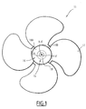
- Figure 1 schematically illustrates a propeller 11 of a motor vehicle fan, for example a front block fan.
- the propeller 11 was made in a mold 13 partially shown in FIG.
- the propeller 11 comprises a hub or central insert 15, a bowl 16 overmolded on the insert 15, and blades 17 integral with the bowl 16 and extending radially outwardly by In the illustrated example, the propeller 11 comprises four blades 17.
- the bowl 16 comprises a bottom 18A and a side wall 18B which protrudes from the bottom 18A.
- the insert 15 comprises a base wall 19, horizontal in the figure, an annular wall 21 projecting vertically downwards from the base wall 19.
- the base wall 19 extends in the inner extension of the bottom 18A of the bowl. It is provided with a central opening 25 of connection to the output shaft of a motor driving in rotation of the helix 11 about a helical axis of rotation.
- the central connection opening 25 extends along an axis X-X 'offset laterally with respect to the central geometric axis Y-Y' of the helix 11.
- the X-X 'and Y-Y' axes are parallel.
- the X-X 'axis passes substantially through the center of inertia of the propeller 11, to reduce its imbalance.
- the base wall 19 and the annular wall 21 internally define a passage 27 for positioning the insert 15 in the mold 13.
- the passage 27 extends along the axis X-X '.
- the passage 27 opens on the one hand into the central orifice 25 and on the other hand at the lower end 29 of the annular wall 21.
- the blades 17 extend radially outwardly from the side wall 18A and are angularly spaced from each other.
- the blades 17 are adapted to produce an air flow substantially parallel to the axis of rotation X-X 'when the helix 11 rotates about this axis.
- the mold 13 comprises a lower half-mold 41, in which is mounted a rod 43 for positioning the insert 15, an upper half-mold 45, and means 47 for off-centering the rod positioning 43.
- the upper half molds 45 and lower mold half 41 define, when in the closed position of the mold 13, shown in Figure 2, a molding cavity 49 of complementary shape of the mold. 11.
- the shape of the molding cavity 49 defines the central geometric axis YY 'of the helix 11.
- the lower half-mold 41 comprises a hollow wall 51 forming a plurality of annular steps 53A, 53B and 53C extending around the central geometric axis Y-Y '.
- a passage 55 for receiving the positioning rod 43 is formed at the bottom of the hollow wall 51. This passage 55 extends along the central geometric axis Y-Y '.
- This shoulder 53C comprises a side wall 57, diverging towards the cavity 49.
- the wall 37 has a shape complementary to the outer surface of the annular wall 21 at its lower end 29, with the interposition of a functional clearance.
- the lower half-mold 41 is movable in translation along the central geometric axis Y-Y ', between an open position of the mold 13, in which the lower half-mold 41 is separated from the half upper mold 45, and a closed position of the mold 13, wherein the lower half-mold 41 bears on the upper half-mold 45.
- the upper half-mold 45 is fixed axially.
- the lower half-mold 41 is fixed axially and the upper half-mold 45 is able to move in translation along the axis Y-Y '.
- the rod 43 for positioning the insert comprises a lower portion 61 disposed in the lower half-mold 41 and an insert support head 63 that protrudes into the molding cavity 49.
- the lower part 61 is engaged in the receiving passage 55 with the interposition of an annular clearance.
- the rod 43 is thus movable radially from the central geometric axis YY 'between a central position in which the rod 43 is away from the mold half 41 and eccentric positions in which the rod 43 is in contact with the half -mold 41.
- the head 63 has an outer surface 65 of complementary shape to the positioning passage 27.
- the eccentric means 47 of the positioning rod 43 comprise a pin 71 screwed into the upper half-mold 45 and which projects into the molding cavity 49.
- the means 47 also comprise a receiving cavity 73, formed in the head 63 of the rod 43, coaxially with the rod 43.
- the pin 71 comprises a base 75 and a portion 77 projecting from the base 75, integral with the base 75.
- the pin 71 is for example made by machining a initial cylindrical part.
- the base 75 is generally cylindrical in shape and has a thread on its outer radial surface.
- the projecting portion 77 is of diameter less than the diameter of the base 75.
- the longitudinal axis XX 'of the projecting portion 77 is offset laterally with respect to the longitudinal axis YY' of the base 77. part 77 protrudes into the molding cavity 49 when the pin 71 is mounted in the upper half-mold 45.
- the projecting portion 77 has a shape complementary to that of the receiving cavity 73 in the head 63, and a frustoconical lower end 79, converging towards the lower half-mold 41, away from the upper half-mold 45 when the post 71 is mounted in this half-mold 45.
- a form of screwing 81 is formed in the lower surface 82 of the protruding portion 77 to receive the end of a screwing means.
- the base 75 is screwed into a threaded housing 83 of complementary shape formed in the upper half-mold 45 and opening in the molding cavity 49.
- the housing 83 extends along the central geometric axis Y-Y ' .
- This method comprises a step of molding a plurality of propeller blanks in the mold 13, a step of determining the average eccentricity of the propeller blanks, a step of machining a pin 71 on the base of the determined average eccentricity, and a molding step of the propellers 11 of low unbalance.
- a plurality of blanks having an axis of rotation coincides with the central geometric axis Y-Y 'is produced.
- a reference pin (not shown), which has a protruding portion 77 coaxial with its base 75 is inserted into the upper half-mold 45 when the mold is in the open position.
- an insert 15 is disposed on the positioning rod 43, the head 63 being received in the passage 27 and the lower end 29 of the insert resting on the lower step 53C.
- the mold 13 is then closed by moving the half-mold 41 to the half-mold 45.
- the projecting portion 77 enters the cavity 73 of the head 53 through the central opening 25 of the insert 15 during this displacement .
- the propeller blank is formed by injecting a plastic material into the molding cavity 49 over-molding the insert 15, and cooling.
- the average eccentricity of the center of inertia of the propeller blanks with respect to the central geometric axis Y-Y ' is determined. Furthermore, the angular position of the center of inertia around the central geometric axis Y-Y 'is measured on each helix and a mean angular position around this axis is calculated.
- a locating pin 71 is made on the basis of the determined average eccentricity.
- the pin 71 is made with a projecting portion 77 of axis XX 'offset laterally with respect to the axis YY' of the base 75, a value substantially equal to the determined average eccentricity of the blanks d 'propeller.
- the molding step of the low unbalance propellers 11 comprises an insertion sub-step of the post 71 made at the machining step in the housing 83, and a substep of molding in the mold 13 of a series of propellers 11 having a low unbalance.
- the pin 71 is screwed into the upper half-mold 45.
- the position of the axis X-X 'around the central geometric axis Y-Y' is defined by the structure of the post 71, as regards its distance to the axis YY '.
- the position of the X-X 'axis is set angularly around the Y-Y' axis by rotating the pin 71.
- the mold 13 In the molding phase of each propeller 11 of low unbalance, the mold 13 is initially held in the open position. An insert 15 is disposed on the positioning rod 43 and the mold 13 is closed.
- the convergent end 79 of the protruding portion 77 penetrates progressively into the cavity 73 and guides the displacement of the rod 43 so that it aligns with the axis X-X '.
- the insert 15 moves laterally with the rod 43 by sliding its lower end 29 in the functional clearance between the diverging wall 57 and the end 29.
- the central opening 25 extends along the axis X-X '.
- a molten plastic material is then injected into the mold and then cooled to form the helix 11 by overmoulding on the insert 15.
- This propeller 11 has a low unbalance, since its axis of rotation, which corresponds to the axis X-X 'when the propeller 11 is in the mold 13, substantially passes through its center of inertia.
- a new pin 71 is machined on the basis of the modified eccentration of the center of inertia.
- the convergent shape of the lower end 79 facilitates the guiding of the positioning rod 43 during the closure of the mold 13, particularly if the axis of rotation XX 'of the propeller 11 is strongly offset with respect to the geometric axis central Y-Y '.
- the helix 11 is devoid of insert 15.
- the bowl 16 is molded by injecting molten plastic material into the cavity 49 around the projecting portion 77 of the post 71 and around the head 73. After cooling, the The region of the bowl 16 located in the vicinity of the portion 77 and the head 73 forms a connection region to a propeller rotating shaft comprising a central opening 25 of connection. The position of the connection region on the propeller 11 is adjusted by the positioning of the post 71 and the rod 43.
Landscapes
- Engineering & Computer Science (AREA)
- Manufacturing & Machinery (AREA)
- Mechanical Engineering (AREA)
- Moulds For Moulding Plastics Or The Like (AREA)
Abstract
Description
- La présente invention concerne un moule de réalisation d'une hélice pour ventilateur de véhicule automobile, l'hélice comprenant une région de liaison à un arbre d'entraînement en rotation de l'hélice autour d'un axe de rotation, le moule étant du type décrit dans le préambule de la revendication 1.
- L'invention s'applique en particulier à la réalisation d'hélices pour ventilateurs de véhicules automobiles.
- Un tel ventilateur, généralement dénommé groupe moto-ventilateur (GMV) est disposé par exemple en avant du radiateur de refroidissement du moteur thermique d'un véhicule automobile, pour améliorer par convection forcée l'échange de chaleur entre l'air extérieur et le fluide de refroidissement du moteur thermique circulant dans le radiateur.
- L'hélice d'un tel ventilateur est réalisée par exemple par injection de matière sur un insert de liaison à un arbre d'entraînement en rotation de l'hélice, dans un moule du type précité.
- L'hélice ainsi réalisée présente, dans certains cas, une répartition non homogène des masses dans sa structure, ce qui engendre un balourd lors de la rotation de l'hélice.
- Ce balourd induit un décalage du centre d'inertie de l'hélice par rapport à son axe de rotation.
- Pour pallier ce problème, et diminuer le balourd de l'hélice, on connaît de US 5 409 656 un moule du type précité, qui permet de réaliser une hélice dont l'axe de rotation passe sensiblement par le centre d'inertie de l'hélice.
- A cet effet, le moule comprend un organe de positionnement de l'insert de liaison, monté mobile dans le premier demi-moule et des moyens d'excentration de l'organe de positionnement constitués par deux bagues montées rotatives dans le premier demi-moule. La rotation des bagues permet de bloquer en position l'organe de positionnement par rapport au premier demi-moule pour décaler latéralement l'axe de rotation de l'hélice par rapport à l'axe géométrique de l'hélice.
- Un tel moule ne donne pas entière satisfaction. En effet, un mécanisme complexe de réglage est nécessaire pour excentrer l'organe de positionnement et le maintenir dans une position excentrée. Le coût d'un tel moule est donc élevé.
- Un but de la présente invention est donc de fournir un moule du type précité, qui présente un coût réduit, tout en permettant de réaliser une hélice de faible balourd.
- A cet effet, l'invention a pour objet un moule selon la revendication 1.
- Le moule selon l'invention peut présenter l'une ou plusieurs des caractéristiques qui font l'objet des revendications 2 à 8, prise(s) isolément ou selon toutes les combinaisons techniquement possibles.
- L'invention a en outre pour objet un procédé de réalisation d'une hélice pour ventilateur de véhicule automobile selon la revendication 9.
- L'invention sera mieux comprise à la lecture de la description qui va suivre, donnée uniquement à titre d'exemple, et faite en se référant aux dessins annexés, sur lesquels :
- la figure 1 est une vue de face d'une hélice réalisée dans un moule selon l'invention ;
- la figure 2 est une vue en coupe prise suivant un plan vertical médian des parties pertinentes d'un moule selon l'invention ; et
- la figure 3 est une vue partielle de côté d'un détail de la figure 2.
- La figure 1 illustre schématiquement une hélice 11 de ventilateur de véhicule automobile, par exemple de ventilateur de bloc avant. L'hélice 11 a été réalisée dans un moule 13 représenté partiellement à la figure 2.
- En référence à la figure 1, l'hélice 11 comprend un moyeu ou insert 15 central, un bol 16 surmoulé sur l'insert 15, et des pales 17 venues de matière avec le bol 16 et s'étendant radialement vers l'extérieur par rapport au bol 16. Dans l'exemple illustré, l'hélice 11 comprend quatre pales 17.
- Le bol 16 comprend un fond 18A et une paroi latérale 18B qui fait saillie à partir du fond 18A.
- Comme illustré par la figure 2, l'insert 15 comprend une paroi de base 19, horizontale sur la figure, une paroi annulaire 21 qui fait saillie verticalement vers le bas à partir de la paroi de base 19.
- La paroi de base 19 s'étend dans le prolongement intérieur du fond 18A du bol. Elle est munie d'une ouverture centrale 25 de liaison à l'arbre de sortie d'un moteur d'entraînement en rotation de l'hélice 11 autour d'un axe de rotation d'hélice.
- Comme illustré par la figure 1, l'ouverture centrale de liaison 25 s'étend suivant un axe X-X' décalé latéralement par rapport à l'axe géométrique central Y-Y' de l'hélice 11. Les axes X-X' et Y-Y' sont parallèles. L'axe X-X' passe sensiblement par le centre d'inertie de l'hélice 11, afin de diminuer son balourd.
- La paroi de base 19 et la paroi annulaire 21 délimitent intérieurement un passage 27 de positionnement de l'insert 15 dans le moule 13. Le passage 27 s'étend le long de l'axe X-X'.
- Le passage 27 débouche, d'une part, dans l'orifice central 25 et d'autre part, à l'extrémité inférieure 29 de la paroi annulaire 21.
- Comme représenté à la Figure 1, les pales 17 s'étendent radialement vers l'extérieur à partir de la paroi latérale 18A et sont espacées angulairement les unes des autres. Les pales 17 sont propres à produire un écoulement d'air sensiblement parallèle à l'axe de rotation X-X' lorsque l'hélice 11 tourne autour de cet axe.
- En référence à la figure 2, le moule 13 comprend un demi-moule inférieur 41, dans lequel est montée une tige 43 de positionnement de l'insert 15, un demi-moule supérieur 45, et des moyens 47 d'excentration de la tige de positionnement 43.
- Comme on le verra plus bas, les demi-moule supérieur 45 et demi-moule inférieur 41 délimitent, lorsqu'ils sont dans la position de fermeture du moule 13, représentée sur la figure 2, une cavité de moulage 49 de forme complémentaire de l'hélice 11. La forme de la cavité de moulage 49 définit l'axe géométrique central Y-Y' de l'hélice 11.
- Le demi-moule inférieur 41 comprend une paroi creuse 51 formant une pluralité de gradins annulaires 53A, 53B et 53C s'étendant autour de l'axe géométrique central Y-Y'.
- Un passage 55 de réception de la tige de positionnement 43 est ménagé au fond de la paroi creuse 51 Ce passage 55 s'étend le long de l'axe géométrique central Y-Y'.
- Le gradin 53C disposé au fond de la paroi 51, à l'extrémité supérieure du passage 55, délimite un épaulement de support de l'extrémité inférieure 29 de l'insert 15.
- Cet épaulement 53C comprend une paroi latérale 57, divergeant vers la cavité 49. La paroi 37 a une forme complémentaire à la surface extérieure de la paroi annulaire 21 à son extrémité inférieure 29, avec interposition d'un jeu fonctionnel.
- Dans cet exemple, le demi-moule inférieur 41 est mobile en translation le long de l'axe géométrique central Y-Y', entre une position d'ouverture du moule 13, dans laquelle le demi-moule inférieur 41 est écarté du demi-moule supérieur 45, et une position de fermeture du moule 13, dans laquelle le demi-moule inférieur 41 est en appui sur le demi-moule supérieur 45. Le demi-moule supérieur 45 est fixe axialement.
- En variante, le demi-moule inférieur 41 est fixé axialement et le demi-moule supérieur 45 est mobile en translation le long de l'axe Y-Y'.
- La tige 43 de positionnement de l'insert comprend une partie inférieure 61 disposée dans le demi-moule inférieur 41 et une tête de support d'insert 63 qui fait saillie dans la cavité de moulage 49.
- La partie inférieure 61 est engagée dans le passage de réception 55 avec interposition d'un jeu annulaire. La tige 43 est ainsi mobile radialement à partir de l'axe géométrique central Y-Y' entre une position centrale dans laquelle la tige 43 est à l'écart du demi-moule 41 et des positions excentrées dans lesquelles la tige 43 est au contact du demi-moule 41.
- La tête 63 présente une surface extérieure 65 de forme complémentaire au passage de positionnement 27.
- Les moyens 47 d'excentration de la tige de positionnement 43 comprennent un tenon 71 vissé dans le demi-moule supérieur 45 et qui fait saillie dans la cavité de moulage 49. Les moyens 47 comprennent également une cavité de réception 73, ménagée dans la tête 63 de la tige 43, coaxialement à la tige 43.
- Dans l'exemple illustré par la figure 3, le tenon 71 comprend une base 75 et une partie 77 en saillie par rapport à la base 75, venue de matière avec la base 75. Le tenon 71 est par exemple réalisé par usinage d'une pièce cylindrique initiale.
- La base 75 est de forme généralement cylindrique et présente un filetage sur sa surface radiale extérieure.
- Dans cet exemple, la partie en saillie 77 est de diamètre inférieur au diamètre de la base 75. L'axe longitudinal X-X' de la partie en saillie 77 est décalé latéralement par rapport à l'axe longitudinal Y-Y' de la base 77. La partie 77 fait saillie dans la cavité de moulage 49 lorsque le tenon 71 est monté dans le demi-moule supérieur 45.
- La partie en saillie 77 présente une forme complémentaire à celle de la cavité de réception 73 dans la tête 63, et une extrémité inférieure 79 de forme tronconique, convergeant vers le demi-moule inférieur 41, à l'écart du demi-moule supérieur 45 lorsque le tenon 71 est monté dans ce demi-moule 45.
- Une forme de vissage 81 est ménagée dans la surface 82 inférieure de la partie en saillie 77 pour recevoir l'extrémité d'un moyen de vissage.
- La base 75 est vissée dans un logement fileté 83 de forme complémentaire ménagé dans le demi-moule supérieur 45 et s'ouvrant dans la cavité de moulage 49. Le logement 83 s'étend le long de l'axe géométrique central Y-Y'.
- Un procédé de réalisation d'une série d'hélices 11 de faible balourd dans un moule 13 selon l'invention va maintenant être décrit.
- Ce procédé comprend une étape de moulage d'une pluralité d'ébauches d'hélices dans le moule 13, une étape de détermination de l'excentration moyenne des ébauches d'hélices, une étape d'usinage d'un tenon 71 sur la base de l'excentration moyenne déterminée, et une étape de moulage des hélices 11 de faible balourd.
- Dans l'étape de moulage des ébauches d'hélices, une pluralité d'ébauches présentant un axe de rotation confondu avec l'axe géométrique central Y-Y' est réalisée.
- A cet effet, un tenon de référence (non représenté), qui présente une partie en saillie 77 coaxiale avec sa base 75 est inséré dans le demi-moule supérieur 45 lorsque le moule est en position ouverte.
- Pour chaque ébauche, un insert 15 est disposé sur la tige de positionnement 43, ia tête 63 étant reçue dans le passage 27 et l'extrémité inférieure 29 de l'insert s'appuyant sur le gradin inférieur 53C.
- Le moule 13 est alors fermé par déplacement du demi-moule 41 vers le demi-moule 45. La partie en saillie 77 pénètre dans la cavité 73 de la tête 53 à travers l'ouverture centrale 25 de l'insert 15 lors de ce déplacement.
- Puis, l'ébauche d'hélice est formée par injection d'une matière plastique dans la cavité de moulage 49 surmoulant l'insert 15, et refroidissement.
- Dans l'étape suivante, l'excentration moyenne du centre d'inertie des ébauches d'hélices par rapport à l'axe géométrique central Y-Y' est déterminée. Par ailleurs, la position angulaire du centre d'inertie autour de l'axe géométrique central Y-Y' est mesuré sur chaque hélice et une position angulaire moyenne autour de cet axe est calculée.
- Dans l'étape d'usinage, un tenon de positionnement 71 est réalisé sur la base de l'excentration moyenne déterminée. A cet effet, le tenon 71 est réalisé avec une partie en saillie 77 d'axe X-X' décalé latéralement par rapport à l'axe Y-Y' de la base 75, d'une valeur sensiblement égale à l'excentration moyenne déterminée des ébauches d'hélice.
- L'étape de moulage des hélices 11 de faible balourd comprend une sous-étape d'insertion du tenon 71 réalisé à l'étape d'usinage dans le logement 83, et une sous-étape de moulage dans le moule 13 d'une série d'hélices 11 présentant un faible balourd.
- Dans la phase d'insertion, le tenon 71 est vissé dans le demi-moule supérieur 45.
- La position de l'axe X-X' autour de l'axe géométrique central Y-Y' est définie par la structure du tenon 71, en ce qui concerne sa distance à l'axe Y-Y'. La position de l'axe X-X' est réglée angulairement autour de l'axe Y-Y' en faisant tourner le tenon 71.
- Dans la phase de moulage de chaque hélice 11 de faible balourd, le moule 13 est maintenu initialement en position ouverte. Un insert 15 est disposé sur la tige de positionnement 43 et le moule 13 est fermé.
- Lors de la fermeture du moule 13, l'extrémité convergente 79 de la partie en saillie 77 pénètre progressivement dans la cavité 73 et guide le déplacement de la tige 43 pour que celle-ci s'aligne avec l'axe X-X'.
- L'insert 15 se déplace latéralement avec la tige 43 par glissement de son extrémité inférieure 29 dans le jeu fonctionnel entre la paroi divergente 57 et l'extrémité 29.
- Lorsque le moule 13 est fermé, l'ouverture centrale de liaison 25 s'étend le long de l'axe X-X'.
- Une matière plastique fondue est alors injectée dans le moule puis refroidie pour former l'hélice 11 par surmoulage sur l'insert 15.
- Cette hélice 11 présente un faible balourd, puisque son axe de rotation, qui correspond à l'axe X-X' lorsque l'hélice 11 est dans le moule 13, passe sensiblement par son centre d'inertie.
- Si la position du centre d'inertie des hélices 11 évolue au cours du temps, par exemple sous l'effet de l'usure du moule 13 ou de modifications des paramètres de moulage, un nouveau tenon 71 est usiné sur la base de l'excentration modifiée du centre d'inertie.
- L'utilisation d'un tenon 71 facilement usinable en fonction de la position du centre d'inertie, pour coopérer avec une tige de positionnement d'insert 43 montée mobile dans le moule 13 permet de réduire le coût du moule 13, tout en permettant la réalisation d'hélices 11 de faible balourd.
- Par ailleurs, le réglage de l'excentration de la tige de positionnement 43 est facilité, puisque les moyens 47 d'excentration de cette tige 43 sont disposés de part et d'autre du moule 13 et sont donc facilement accessibles.
- La forme convergente de l'extrémité inférieure 79 facilite le guidage de la tige de positionnement 43 lors de la fermeture du moule 13, particulièrement si l'axe de rotation X-X' de l'hélice 11 est fortement décalé par rapport à l'axe géométrique central Y-Y'.
- En variante, l'hélice 11 est dépourvue d'insert 15. Le bol 16 est moulé par injection de matière plastique fondue dans la cavité 49 autour de la partie en saillie 77 du tenon 71 et autour de la tête 73. Après refroidissement, la région du bol 16 située au voisinage de la partie 77 et de la tête 73 forme une région de liaison à un arbre d'entraînement en rotation de l'hélice comprenant une ouverture centrale 25 de liaison. La position de la région de liaison sur l'hélice 11 est ajustée par le positionnement du tenon 71 et de la tige 43.
Claims (9)
- Moule (13) de réalisation d'une hélice (11) pour ventilateur de véhicule automobile, l'hélice (11) comprenant une région (15) de liaison à un arbre d'entraînement en rotation de l'hélice (11) autour d'un axe de rotation (X-X'), le moule (13) étant du type comprenant :- des premier et deuxième demi-moules (41, 45), mobiles l'un par rapport à l'autre entre une position d'ouverture du moule (13) et une position de fermeture du moule (13) dans laquelle ils délimitent une cavité de moulage (49), la cavité de moulage (49) définissant un axe géométrique central (Y-Y') d'hélice (11) ;- un organe (43) de positionnement de la région de liaison (15), l'organe de positionnement (43) étant monté mobile dans le premier demi-moule (41) pour positionner la région de liaison (15) dans la cavité de moulage (49) ; et- des moyens (47) d'excentration de l'organe de positionnement (43) pour décaler latéralement l'axe de rotation (X-X') de l'hélice (11) par rapport à l'axe géométrique central (Y-Y') ;caractérisé en ce que les moyens d'excentration (47) comprennent un tenon (71) de blocage en position de l'organe de positionnement (43), monté dans le deuxième demi-moule (45), le tenon (71) faisant saillie dans la cavité de moulage (49) le long d'un axe (X-X') décalé par rapport à l'axe géométrique central (Y-Y') et étant engagé, dans la position de fermeture du moule, dans une cavité (73) de blocage ménagée dans l'organe de positionnement (43).
- Moule (13) selon la revendication 1, caractérisé en ce que le tenon (71) est monté rotatif dans le deuxième demi-moule (45) autour de l'axe géométrique central (Y-Y').
- Moule (13) selon la revendication 1 ou 2, caractérisé en ce que le tenon (71) comprend une base (75) reçue dans un logement (83) du deuxième demi-moule (45) s'étendant le long de l'axe géométrique central (Y-Y'), et une partie en saillie (77) qui s'étend le long de l'axe décalé (X-X') lorsque la base (75) est disposée dans le logement (83) et qui fait saillie dans la cavité de moulage (49).
- Moule (13) selon la revendication 3, caractérisé en ce que la base (75) et la partie en saillie (77) sont venues de matière.
- Moule (13) selon l'une quelconque des revendications 2 à 4, caractérisé en ce que le tenon (71) est vissé dans le deuxième demi-moule (45).
- Moule (13) selon l'une quelconque des revendications précédentes, caractérisé en ce qu'une extrémité (79) du tenon (71) en saillie dans la cavité de moulage (49) présente une forme convergeant vers le premier demi-moule (41).
- Moule (13) selon l'une quelconque des revendications précédentes, caractérisé en ce que le deuxième demi-moule (45) est fixe, le premier demi-moule (41) étant mobile en translation le long de l'axe géométrique central (Y-Y').
- Moule (13) selon l'une quelconque des revendications précédentes, caractérisé en ce que la région de liaison (15) de l'hélice (11) comprend un insert (15), l'organe de positionnement (43) comprenant une surface de support (65) de l'insert (15).
- Procédé de réalisation d'une hélice (11) pour ventilateur de véhicule automobile dans un moule (13) suivant l'une quelconque des revendications précédentes, l'hélice (11) comprenant une région (15) de liaison à un arbre d'entraînement en rotation de l'hélice (11) autour d'un axe de rotation (X-X'), caractérisé en ce qu'il comprend les étapes de :- moulage d'une pluralité d'ébauches d'hélices par injection de matière dans la cavité de moulage (49) ;- détermination d'une excentration moyenne des centres d'inertie des ébauches d'hélice par rapport à leurs axes géométriques centraux (Y-Y') ;- réalisation d'un tenon (71) de blocage en position de l'organe de positionnement (43) sur la base de l'excentration moyenne déterminée ;- montage du tenon (71) usiné sur le deuxième demi-moule (45) ;- blocage en position de l'organe de positionnement (43) par le tenon (71); et- moulage de l'hélice (11) par injection de matière dans la cavité de moulage (49).
Applications Claiming Priority (1)
| Application Number | Priority Date | Filing Date | Title |
|---|---|---|---|
| FR0411662A FR2877255B1 (fr) | 2004-11-02 | 2004-11-02 | Moule de realisation d'une helice pour ventilateur de vehicule automobile et procede associe |
Publications (3)
| Publication Number | Publication Date |
|---|---|
| EP1652647A2 true EP1652647A2 (fr) | 2006-05-03 |
| EP1652647A3 EP1652647A3 (fr) | 2007-02-21 |
| EP1652647B1 EP1652647B1 (fr) | 2008-12-10 |
Family
ID=34953078
Family Applications (1)
| Application Number | Title | Priority Date | Filing Date |
|---|---|---|---|
| EP20050292239 Ceased EP1652647B1 (fr) | 2004-11-02 | 2005-10-24 | Moule de réalisation d'une hélice pour ventilateur de véhicule automobile et procédé associé |
Country Status (3)
| Country | Link |
|---|---|
| EP (1) | EP1652647B1 (fr) |
| DE (1) | DE602005011549D1 (fr) |
| FR (1) | FR2877255B1 (fr) |
Cited By (4)
| Publication number | Priority date | Publication date | Assignee | Title |
|---|---|---|---|---|
| EP2078600A1 (fr) * | 2008-01-11 | 2009-07-15 | Gebr. Schwarz GmbH | Dispositif et procédé destinés à fabriquer un corps de rotation dans le procédé de coulée |
| FR2931383A1 (fr) * | 2008-05-22 | 2009-11-27 | Valeo Systemes Thermiques | Procede et dispositif de moulage d'une helice equilibree, en particulier pour un equipement de vehicule automobile |
| CN110802811A (zh) * | 2019-12-16 | 2020-02-18 | 齐雨光 | 一种注塑模具的冷却机构 |
| CN116038990A (zh) * | 2022-12-30 | 2023-05-02 | 江苏双腾管业有限公司 | 一种钢塑管件加工设备及钢塑管件的加工方法 |
Families Citing this family (2)
| Publication number | Priority date | Publication date | Assignee | Title |
|---|---|---|---|---|
| CN107218241A (zh) * | 2017-07-24 | 2017-09-29 | 温州北工汽车电器有限公司 | 一种冷却风扇总成 |
| EP4717430A1 (fr) * | 2024-09-27 | 2026-04-01 | Sit S.P.A. | Appareil et procédé de production de roues par moulage de matière plastique |
Family Cites Families (2)
| Publication number | Priority date | Publication date | Assignee | Title |
|---|---|---|---|---|
| JPH07115381B2 (ja) * | 1991-09-13 | 1995-12-13 | 日本電装株式会社 | 成形用金型および成形品成形方法 |
| DE60027832T2 (de) * | 1999-09-10 | 2006-09-28 | Calsonic Kansei Corp. | Formvorrichtung zum Formen eines Drehers und Verfahren zu dessen Formung |
-
2004
- 2004-11-02 FR FR0411662A patent/FR2877255B1/fr not_active Expired - Fee Related
-
2005
- 2005-10-24 EP EP20050292239 patent/EP1652647B1/fr not_active Ceased
- 2005-10-24 DE DE200560011549 patent/DE602005011549D1/de not_active Expired - Lifetime
Cited By (4)
| Publication number | Priority date | Publication date | Assignee | Title |
|---|---|---|---|---|
| EP2078600A1 (fr) * | 2008-01-11 | 2009-07-15 | Gebr. Schwarz GmbH | Dispositif et procédé destinés à fabriquer un corps de rotation dans le procédé de coulée |
| FR2931383A1 (fr) * | 2008-05-22 | 2009-11-27 | Valeo Systemes Thermiques | Procede et dispositif de moulage d'une helice equilibree, en particulier pour un equipement de vehicule automobile |
| CN110802811A (zh) * | 2019-12-16 | 2020-02-18 | 齐雨光 | 一种注塑模具的冷却机构 |
| CN116038990A (zh) * | 2022-12-30 | 2023-05-02 | 江苏双腾管业有限公司 | 一种钢塑管件加工设备及钢塑管件的加工方法 |
Also Published As
| Publication number | Publication date |
|---|---|
| EP1652647A3 (fr) | 2007-02-21 |
| EP1652647B1 (fr) | 2008-12-10 |
| DE602005011549D1 (de) | 2009-01-22 |
| FR2877255A1 (fr) | 2006-05-05 |
| FR2877255B1 (fr) | 2007-02-02 |
Similar Documents
| Publication | Publication Date | Title |
|---|---|---|
| FR2703111A1 (fr) | Rotor pour pompe comportant deux pièces assemblées par soudure, obtenues par moulage par injection de matériaux thermoplastiques, et procédé de fabrication d'un tel rotor . | |
| EP1652647B1 (fr) | Moule de réalisation d'une hélice pour ventilateur de véhicule automobile et procédé associé | |
| FR3121855A1 (fr) | Tête de soudage par friction malaxage et procédé l’utilisant | |
| EP2385893B1 (fr) | Système d'injection de matiere thermoplastique | |
| EP3083191B2 (fr) | Élément de moule pour le formage de récipient, pourvu d'évents de décompression sous forme de fentes | |
| EP0469976A1 (fr) | Procédé et machine automatique de fabrication d'anneaux calibrés à partir d'un extrudat filé ou profilé | |
| EP0070763A1 (fr) | Dispositif de moulage de pièces composites en matière plastique | |
| EP3478473B1 (fr) | Procédé et outillage associé pour la fabrication par injection d'un manchon | |
| JP4992679B2 (ja) | ロータリ式射出成形機 | |
| EP0727289B1 (fr) | Ebauche de tournevis, tournevis et gamme de tournevis réalisés à partir d'une telle ébauche, et procédés de fabrication correspondants | |
| FR2878777A1 (fr) | Procede de fabrication d'un composant en matiere plastique a paroi mince | |
| FR3099891A1 (fr) | Rail de guidage, dispositif et procédé de moulage par injection de ce rail. | |
| EP2621792B1 (fr) | Support realise par moulage pour des deplacements sur une ligne d'assemblage | |
| FR2975329A1 (fr) | Moule et procede pour moulage par injection d'une piece avec une partie en saillie | |
| EP2788160B1 (fr) | Ensemble pour la fixation, avec raccordement fluidique, d'un fond de moule sur un support | |
| FR3130187A3 (fr) | Outil de moulage par injection compact pour un capuchon équipé de préférence d’une tige d’applicateur | |
| JP3892337B2 (ja) | 一部突出インサート体を備えた成形品の射出成形装置 | |
| CN208195635U (zh) | 一种倾转式浇铸机 | |
| JP2005280002A (ja) | 金型装置、成形品、その成形方法及び成形機 | |
| EP2002098A1 (fr) | Culasse comprenant un noyau d'eau pourvu d'une partie de degazage et procede de fabrication d'une telle culasse | |
| CN105705845A (zh) | 锥形阀及其制造方法 | |
| FR2984467A1 (fr) | Ailette de dispositif de sortie d'air comprenant un corps chrome | |
| CN114953312A (zh) | 模具的模流调整治具 | |
| FR2784611A1 (fr) | Moule de fabrication d'une piece d'equipement notamment de vehicule automobile | |
| FR2858361A1 (fr) | Systeme d'admission de gaz pour moteur a combustion interne et procede de fabrication d'une culasse pour un tel systeme |
Legal Events
| Date | Code | Title | Description |
|---|---|---|---|
| PUAI | Public reference made under article 153(3) epc to a published international application that has entered the european phase |
Free format text: ORIGINAL CODE: 0009012 |
|
| AK | Designated contracting states |
Kind code of ref document: A2 Designated state(s): AT BE BG CH CY CZ DE DK EE ES FI FR GB GR HU IE IS IT LI LT LU LV MC NL PL PT RO SE SI SK TR |
|
| AX | Request for extension of the european patent |
Extension state: AL BA HR MK YU |
|
| RAP1 | Party data changed (applicant data changed or rights of an application transferred) |
Owner name: FAURECIA COOLING SYSTEMS |
|
| PUAL | Search report despatched |
Free format text: ORIGINAL CODE: 0009013 |
|
| AK | Designated contracting states |
Kind code of ref document: A3 Designated state(s): AT BE BG CH CY CZ DE DK EE ES FI FR GB GR HU IE IS IT LI LT LU LV MC NL PL PT RO SE SI SK TR |
|
| AX | Request for extension of the european patent |
Extension state: AL BA HR MK YU |
|
| RIC1 | Information provided on ipc code assigned before grant |
Ipc: B29C 33/30 20060101ALI20070116BHEP Ipc: B29C 45/14 20060101AFI20060302BHEP Ipc: B29L 31/08 20060101ALN20060302BHEP Ipc: B29C 45/26 20060101ALI20070116BHEP Ipc: B29C 45/37 20060101ALI20070116BHEP |
|
| 17P | Request for examination filed |
Effective date: 20070703 |
|
| 17Q | First examination report despatched |
Effective date: 20070806 |
|
| AKX | Designation fees paid |
Designated state(s): DE ES FR IT |
|
| GRAP | Despatch of communication of intention to grant a patent |
Free format text: ORIGINAL CODE: EPIDOSNIGR1 |
|
| GRAS | Grant fee paid |
Free format text: ORIGINAL CODE: EPIDOSNIGR3 |
|
| GRAS | Grant fee paid |
Free format text: ORIGINAL CODE: EPIDOSNIGR3 |
|
| GRAA | (expected) grant |
Free format text: ORIGINAL CODE: 0009210 |
|
| AK | Designated contracting states |
Kind code of ref document: B1 Designated state(s): DE ES FR IT |
|
| REF | Corresponds to: |
Ref document number: 602005011549 Country of ref document: DE Date of ref document: 20090122 Kind code of ref document: P |
|
| PG25 | Lapsed in a contracting state [announced via postgrant information from national office to epo] |
Ref country code: ES Free format text: LAPSE BECAUSE OF FAILURE TO SUBMIT A TRANSLATION OF THE DESCRIPTION OR TO PAY THE FEE WITHIN THE PRESCRIBED TIME-LIMIT Effective date: 20090321 |
|
| PLBE | No opposition filed within time limit |
Free format text: ORIGINAL CODE: 0009261 |
|
| STAA | Information on the status of an ep patent application or granted ep patent |
Free format text: STATUS: NO OPPOSITION FILED WITHIN TIME LIMIT |
|
| 26N | No opposition filed |
Effective date: 20090911 |
|
| REG | Reference to a national code |
Ref country code: FR Ref legal event code: TP |
|
| PG25 | Lapsed in a contracting state [announced via postgrant information from national office to epo] |
Ref country code: IT Free format text: LAPSE BECAUSE OF FAILURE TO SUBMIT A TRANSLATION OF THE DESCRIPTION OR TO PAY THE FEE WITHIN THE PRESCRIBED TIME-LIMIT Effective date: 20081210 |
|
| REG | Reference to a national code |
Ref country code: FR Ref legal event code: PLFP Year of fee payment: 12 |
|
| REG | Reference to a national code |
Ref country code: FR Ref legal event code: PLFP Year of fee payment: 13 |
|
| PGFP | Annual fee paid to national office [announced via postgrant information from national office to epo] |
Ref country code: FR Payment date: 20170921 Year of fee payment: 13 |
|
| PGFP | Annual fee paid to national office [announced via postgrant information from national office to epo] |
Ref country code: DE Payment date: 20170920 Year of fee payment: 13 |
|
| REG | Reference to a national code |
Ref country code: DE Ref legal event code: R119 Ref document number: 602005011549 Country of ref document: DE |
|
| PG25 | Lapsed in a contracting state [announced via postgrant information from national office to epo] |
Ref country code: DE Free format text: LAPSE BECAUSE OF NON-PAYMENT OF DUE FEES Effective date: 20190501 |
|
| PG25 | Lapsed in a contracting state [announced via postgrant information from national office to epo] |
Ref country code: FR Free format text: LAPSE BECAUSE OF NON-PAYMENT OF DUE FEES Effective date: 20181031 |