EP1652655A2 - Méthode de production d'un modèle par prototypage rapide comprenant des domaines électriquement conducteurs - Google Patents
Méthode de production d'un modèle par prototypage rapide comprenant des domaines électriquement conducteurs Download PDFInfo
- Publication number
- EP1652655A2 EP1652655A2 EP05109816A EP05109816A EP1652655A2 EP 1652655 A2 EP1652655 A2 EP 1652655A2 EP 05109816 A EP05109816 A EP 05109816A EP 05109816 A EP05109816 A EP 05109816A EP 1652655 A2 EP1652655 A2 EP 1652655A2
- Authority
- EP
- European Patent Office
- Prior art keywords
- rapid prototyping
- model
- electrically conductive
- ceramic
- prototyping model
- Prior art date
- Legal status (The legal status is an assumption and is not a legal conclusion. Google has not performed a legal analysis and makes no representation as to the accuracy of the status listed.)
- Withdrawn
Links
Images


Classifications
-
- A—HUMAN NECESSITIES
- A61—MEDICAL OR VETERINARY SCIENCE; HYGIENE
- A61C—DENTISTRY; APPARATUS OR METHODS FOR ORAL OR DENTAL HYGIENE
- A61C13/00—Dental prostheses; Making same
- A61C13/0003—Making bridge-work, inlays, implants or the like
- A61C13/0022—Blanks or green, unfinished dental restoration parts
-
- A—HUMAN NECESSITIES
- A61—MEDICAL OR VETERINARY SCIENCE; HYGIENE
- A61C—DENTISTRY; APPARATUS OR METHODS FOR ORAL OR DENTAL HYGIENE
- A61C13/00—Dental prostheses; Making same
- A61C13/0003—Making bridge-work, inlays, implants or the like
- A61C13/0006—Production methods
- A61C13/001—Electrophoresis coating
-
- A—HUMAN NECESSITIES
- A61—MEDICAL OR VETERINARY SCIENCE; HYGIENE
- A61C—DENTISTRY; APPARATUS OR METHODS FOR ORAL OR DENTAL HYGIENE
- A61C13/00—Dental prostheses; Making same
- A61C13/0003—Making bridge-work, inlays, implants or the like
- A61C13/0006—Production methods
- A61C13/0012—Electrolytic coating
-
- B—PERFORMING OPERATIONS; TRANSPORTING
- B29—WORKING OF PLASTICS; WORKING OF SUBSTANCES IN A PLASTIC STATE IN GENERAL
- B29C—SHAPING OR JOINING OF PLASTICS; SHAPING OF MATERIAL IN A PLASTIC STATE, NOT OTHERWISE PROVIDED FOR; AFTER-TREATMENT OF THE SHAPED PRODUCTS, e.g. REPAIRING
- B29C64/00—Additive manufacturing, i.e. manufacturing of three-dimensional [3D] objects by additive deposition, additive agglomeration or additive layering, e.g. by 3D printing, stereolithography or selective laser sintering
- B29C64/10—Processes of additive manufacturing
- B29C64/106—Processes of additive manufacturing using only liquids or viscous materials, e.g. depositing a continuous bead of viscous material
-
- B—PERFORMING OPERATIONS; TRANSPORTING
- B29—WORKING OF PLASTICS; WORKING OF SUBSTANCES IN A PLASTIC STATE IN GENERAL
- B29C—SHAPING OR JOINING OF PLASTICS; SHAPING OF MATERIAL IN A PLASTIC STATE, NOT OTHERWISE PROVIDED FOR; AFTER-TREATMENT OF THE SHAPED PRODUCTS, e.g. REPAIRING
- B29C64/00—Additive manufacturing, i.e. manufacturing of three-dimensional [3D] objects by additive deposition, additive agglomeration or additive layering, e.g. by 3D printing, stereolithography or selective laser sintering
- B29C64/10—Processes of additive manufacturing
- B29C64/106—Processes of additive manufacturing using only liquids or viscous materials, e.g. depositing a continuous bead of viscous material
- B29C64/112—Processes of additive manufacturing using only liquids or viscous materials, e.g. depositing a continuous bead of viscous material using individual droplets, e.g. from jetting heads
-
- B—PERFORMING OPERATIONS; TRANSPORTING
- B29—WORKING OF PLASTICS; WORKING OF SUBSTANCES IN A PLASTIC STATE IN GENERAL
- B29C—SHAPING OR JOINING OF PLASTICS; SHAPING OF MATERIAL IN A PLASTIC STATE, NOT OTHERWISE PROVIDED FOR; AFTER-TREATMENT OF THE SHAPED PRODUCTS, e.g. REPAIRING
- B29C64/00—Additive manufacturing, i.e. manufacturing of three-dimensional [3D] objects by additive deposition, additive agglomeration or additive layering, e.g. by 3D printing, stereolithography or selective laser sintering
- B29C64/10—Processes of additive manufacturing
- B29C64/106—Processes of additive manufacturing using only liquids or viscous materials, e.g. depositing a continuous bead of viscous material
- B29C64/118—Processes of additive manufacturing using only liquids or viscous materials, e.g. depositing a continuous bead of viscous material using filamentary material being melted, e.g. fused deposition modelling [FDM]
-
- B—PERFORMING OPERATIONS; TRANSPORTING
- B29—WORKING OF PLASTICS; WORKING OF SUBSTANCES IN A PLASTIC STATE IN GENERAL
- B29C—SHAPING OR JOINING OF PLASTICS; SHAPING OF MATERIAL IN A PLASTIC STATE, NOT OTHERWISE PROVIDED FOR; AFTER-TREATMENT OF THE SHAPED PRODUCTS, e.g. REPAIRING
- B29C64/00—Additive manufacturing, i.e. manufacturing of three-dimensional [3D] objects by additive deposition, additive agglomeration or additive layering, e.g. by 3D printing, stereolithography or selective laser sintering
- B29C64/10—Processes of additive manufacturing
- B29C64/106—Processes of additive manufacturing using only liquids or viscous materials, e.g. depositing a continuous bead of viscous material
- B29C64/124—Processes of additive manufacturing using only liquids or viscous materials, e.g. depositing a continuous bead of viscous material using layers of liquid which are selectively solidified
- B29C64/129—Processes of additive manufacturing using only liquids or viscous materials, e.g. depositing a continuous bead of viscous material using layers of liquid which are selectively solidified characterised by the energy source therefor, e.g. by global irradiation combined with a mask
- B29C64/135—Processes of additive manufacturing using only liquids or viscous materials, e.g. depositing a continuous bead of viscous material using layers of liquid which are selectively solidified characterised by the energy source therefor, e.g. by global irradiation combined with a mask the energy source being concentrated, e.g. scanning lasers or focused light sources
-
- B—PERFORMING OPERATIONS; TRANSPORTING
- B29—WORKING OF PLASTICS; WORKING OF SUBSTANCES IN A PLASTIC STATE IN GENERAL
- B29C—SHAPING OR JOINING OF PLASTICS; SHAPING OF MATERIAL IN A PLASTIC STATE, NOT OTHERWISE PROVIDED FOR; AFTER-TREATMENT OF THE SHAPED PRODUCTS, e.g. REPAIRING
- B29C64/00—Additive manufacturing, i.e. manufacturing of three-dimensional [3D] objects by additive deposition, additive agglomeration or additive layering, e.g. by 3D printing, stereolithography or selective laser sintering
- B29C64/10—Processes of additive manufacturing
- B29C64/165—Processes of additive manufacturing using a combination of solid and fluid materials, e.g. a powder selectively bound by a liquid binder, catalyst, inhibitor or energy absorber
-
- B—PERFORMING OPERATIONS; TRANSPORTING
- B33—ADDITIVE MANUFACTURING TECHNOLOGY
- B33Y—ADDITIVE MANUFACTURING, i.e. MANUFACTURING OF THREE-DIMENSIONAL [3D] OBJECTS BY ADDITIVE DEPOSITION, ADDITIVE AGGLOMERATION OR ADDITIVE LAYERING, e.g. BY 3D PRINTING, STEREOLITHOGRAPHY OR SELECTIVE LASER SINTERING
- B33Y70/00—Materials specially adapted for additive manufacturing
-
- B—PERFORMING OPERATIONS; TRANSPORTING
- B33—ADDITIVE MANUFACTURING TECHNOLOGY
- B33Y—ADDITIVE MANUFACTURING, i.e. MANUFACTURING OF THREE-DIMENSIONAL [3D] OBJECTS BY ADDITIVE DEPOSITION, ADDITIVE AGGLOMERATION OR ADDITIVE LAYERING, e.g. BY 3D PRINTING, STEREOLITHOGRAPHY OR SELECTIVE LASER SINTERING
- B33Y70/00—Materials specially adapted for additive manufacturing
- B33Y70/10—Composites of different types of material, e.g. mixtures of ceramics and polymers or mixtures of metals and biomaterials
-
- B—PERFORMING OPERATIONS; TRANSPORTING
- B29—WORKING OF PLASTICS; WORKING OF SUBSTANCES IN A PLASTIC STATE IN GENERAL
- B29K—INDEXING SCHEME ASSOCIATED WITH SUBCLASSES B29B, B29C OR B29D, RELATING TO MOULDING MATERIALS OR TO MATERIALS FOR MOULDS, REINFORCEMENTS, FILLERS OR PREFORMED PARTS, e.g. INSERTS
- B29K2995/00—Properties of moulding materials, reinforcements, fillers, preformed parts or moulds
- B29K2995/0003—Properties of moulding materials, reinforcements, fillers, preformed parts or moulds having particular electrical or magnetic properties, e.g. piezoelectric
- B29K2995/0005—Conductive
-
- B—PERFORMING OPERATIONS; TRANSPORTING
- B29—WORKING OF PLASTICS; WORKING OF SUBSTANCES IN A PLASTIC STATE IN GENERAL
- B29L—INDEXING SCHEME ASSOCIATED WITH SUBCLASS B29C, RELATING TO PARTICULAR ARTICLES
- B29L2031/00—Other particular articles
- B29L2031/753—Medical equipment; Accessories therefor
- B29L2031/7532—Artificial members, protheses
- B29L2031/7536—Artificial teeth
Definitions
- the invention relates to a method for producing a rapid prototyping model for electrolytic or electrophoretic deposition. According to a further aspect, the invention relates to a method for producing a ceramic green compact. The invention further relates to a method for producing a ceramic component, a method for producing a rapid prototyping model with a metallic coating and a method for producing a metallic component. Finally, the invention relates to the use of a 3D printer.
- rapid prototyping models of, for example, wax or plastic.
- the ink-jet technology is used.
- one or more printhead / heads dispense small globules of liquid material which impinge upon and solidify on the resulting rapid prototyping model.
- pointwise the rapid prototyping model is built.
- Another method of additive construction of a rapid prototyping model is stereolithography.
- resin is applied in layers and selectively irradiated by light.
- the areas of the resin that are irradiated crosslink.
- the excess, uncrosslinked resin content can be easily removed. What remains is a three-dimensional rapid prototyping model.
- the surface of the rapid prototyping model is e.g. made conductive with a conductive paint (e.g., silver conductive paint) or sputtering.
- a conductive paint e.g., silver conductive paint
- the rapid prototyping models for example, electrolytically coated; Alternatively, slip is attached to the conductive-coated rapid prototyping models in an electrophoretic process. In the process, a ceramic layer settles, from which a green body and finally a ceramic component are produced in further process steps.
- Examples of applications resulting from the combination of rapid prototyping processes with conductibility and the coating or deposition of slip are the production of metallic or ceramic coatings or molded parts. This can be used to produce individual parts as well as small series from the final material while saving costs and time. In addition, however, the generation of three-dimensional microstructures or microstructured surfaces leads to new fields of application in microsystems and micro process engineering.
- a disadvantage of applying a Leitlacks is that it comes to its use not exactly predictable geometry changes.
- the sputtering method for the rapid prototyping model results in lower layer thicknesses for structural surfaces perpendicular to the sputtering beam than in the case of structure surfaces running horizontally to the sputtering beam.
- the thinner layers formed in the latter case have a higher electrical resistance.
- WO 02/064335 A1 discloses certain methods of 3D printing.
- DE 103 32 802 A1 discloses methods for producing a load-bearing structure made of oxide ceramics.
- DE 103 11 446 A1 discloses a method for joining material for the production of moldings by means of selective inhibition.
- EP 0 420 614 A1 discloses methods for coating stereolithographic parts.
- the invention has for its object to overcome disadvantages in the prior art.
- the invention solves the problem by using a 3D printer with one, two or more printing systems and / or printheads to express a rapid prototyping model comprising one or more solidified materials in one or more areas of its surface comprises one or more electrically conductive substances.
- rapid prototyping is understood to mean methods which generate data of the same geometrical dimensions from data stored in a computer (computer) which describe the geometry of a component, without requiring human intervention with regard to the design.
- a computer computer
- the components described in the computer by geometric data are favorably tested by the use of software tools with regard to their later physical properties. So it is e.g. makes sense to calculate the mechanical stability and the mass of the finished component and to compare it with the specification.
- a fluid material is understood as meaning a material which has a viscosity of less than 1000 Pa ⁇ s at a given temperature and given pressure.
- Solidifying fluid materials are particularly when they can be converted by cooling, evaporation of a volatile component, polymerization, light curing, setting or crosslinking in the solid state.
- substances that are solid at 20 ° C and 1013 hPa and at elevated temperature (eg in the range of 50 ° C to 250 ° C) and 1013 hPa one Viscosity of less than 10 Pa ⁇ s, at this temperature and pressure to the fluid, solidifiable materials. They (re) frozen on cooling.
- Mixtures are, for example, suspensions, emulsions or solutions.
- the mixture used in the process according to the invention comprises one or more additives.
- the mixture comprises, for example, a dispersing agent which causes its homogenization and stabilization via electrostatic and / or steric interaction with any particles present.
- a wetting agent can be provided which allows the addition of one or more electrically conductive powders with a high surface tension. It is also possible to use materials which serve as thickeners or diluents of the mixture.
- Electrodeposition is understood to mean the migration of ions in a DC electric field and their discharge at an electrode to form a coating of the substance resulting from the discharged ions.
- electroforming also called electroforming
- electroplating Galvanoplastics produce metallic objects through electrolytic processes.
- Electroplating is used to produce metallic coatings. Electroplating can in turn be subdivided into functional and decorative electroplating.
- the functional electroplating technique serves to produce functional coatings, for example for corrosion protection, wear protection, to improve catalytic properties or to improve electrical conductivity.
- Examples of functional electroplating are the galvanizing of screws, the hard chrome plating of machine parts, the gilding or silvering of electrical contacts and the coating of carrier substrates with catalytically active metal layers for the production of catalysts for the chemical industry or for the production of fuel cells.
- the decorative electroplating technique is used to produce metallic decorative layers. Examples include plastic plating, the chrome plating of tubular steel furniture and the gilding of jewelry and cutlery.
- Electrophoretic deposition is understood to mean the migration in a liquid of dispersed particles in a DC electric field, in which the deposition of these particles occurs in the vicinity of an electrode.
- the dispersed particles are usually leached in an aqueous or organic dispersant in the presence of peptizers. This forms particles with pronounced electrical double layers.
- agglomerate the dispersed particles In a sufficiently strong electric field in the immediate vicinity of the electrode agglomerate the dispersed particles, and it forms a densely packed particle assembly, which precisely shapes the surface structure of the electrode.
- subsequent steps such as drying and / or sintering, ceramic components are obtained, which have only low residual stresses, density gradients and composition variations, which is favorable in terms of life and wear behavior.
- An electrically conductive region of a surface is understood in particular to mean a surface region of a spatial segment in which the specific electrical resistance is less than 500 ⁇ m.
- the electrical conductivity of an electrically conductive region of the surface generally results, in particular, from the fact that the space section comprising this region consists of material which, during the production of the rapid prototyping model, consists of the mixture of one or more fluid, solidifiable materials and one or more electrically conductive substances has emerged.
- An electrically conductive substance is understood in particular to mean a substance having a specific electrical resistance of less than 500 ⁇ m.
- a ceramic green compact is understood to mean a ceramic body which is mechanically stable to such an extent that it bears its own weight permanently and is therefore mechanically stable, but which again becomes mechanically unstable as a result of storage in water. Ceramic green compacts can be transferred by sintering into a ceramic component. A ceramic component is permanently mechanically stable even in water.
- An advantage of the invention is first the saving of human labor, since the step of electrical contacting by applying an electrically conductive layer, for example by hand is eliminated.
- the contacting is then particularly easily possible via electrodes, if corresponding contacts are already created in rapid prototyping.
- the higher dimensional accuracy is advantageous because no additional layers have to be applied to the surface of the rapid prototyping model in the method according to the invention. Due to the high dimensional accuracy, the production of precision components is also possible.
- graphite, carbon black, other conductive substances based on carbon (preferably with carbon-6-ring layers) and / or metal particles, preferably silver particles, are used as electrically conductive substances. It has been found that rapid prototyping models can be produced with these materials which are mechanically stable and, at the same time, are particularly highly electrically conductive in one or more areas of their surface due to the presence of the electrically conductive substance.
- the use of graphite, carbon black and other carbon-based conductive substances is particularly preferred.
- Another advantage of the invention is that due to the inventively provided porosity in the interior of the model (ie below the top or outer surface, which is electrophoretically or electrolytically coated), the removal of the model from the deposited layer or the green compact or component (ceramic and / or metallic) is significantly easier compared with the use of compact models.
- the specific electrical resistance of the conductive areas is less than 500 ⁇ m. This contributes to the fact that deposited ceramic or metal layers are not too different in layer thickness.
- the electrical conductivity of the mixture hardly differs from the electrical conductivity of the fluid, solidifiable materials alone.
- the electrical conductivity of the mixture usually increases in proportion to the concentration of the electrically conductive substance (s).
- concentration of the electrically conductive substance (s) in the mixture a strongly disproportionate rise of the electrical conductivity is observed starting from a certain concentration. The reason for this lies in the formation of a continuous network, which consists of so-called conductive paths through the material.
- the concentration at which the increase in conductivity becomes disproportionate is the percolation concentration.
- the concentration of the electrically conductive substances in the mixture is plotted against the electrical conductivity (conductivity curve), then the percolation concentration is exceeded, in particular at concentrations which are higher than the concentration at which the first inflection point lies in which the conductivity curve is from a convex to a conductivity curve concave curvature passes.
- the proportion of the electrically conductive substances in the mixture is selected to be so high that the rapid prototyping model produced by rapid prototyping is conductive in one or more areas of its surface and at the same time the mixture has material properties which ensure that the mixture can be used in the rapid mode. Allow prototyping process.
- the proportion of conductive substances is limited to the top by the predetermined by the rapid prototyping process properties of the material to be built orprooftragenden.
- the proportion of electrically conductive substances in the mixture is varied over wide limits and it is determined at which proportion the applicability is optimal.
- the proportion of electrically conductive substances is chosen so that the viscosity of the mixture is optimal for the execution of the rapid prototyping process.
- electrically conductive substances which consist of small particles, in particular with an average particle diameter in the range of 5 nm to 50 .mu.m, in particular 10 nm to 10 .mu.m. It has also proven to be favorable to use electrically conductive substances which have a multimodal particle distribution. It can be a bimodal or trimodal distribution. As a result, the viscosity and the conductivity of the material can be favorably influenced.
- copper chloride preferably 3 to 6 moles per gram of mixture, has proven to be favorable, especially when the fluid, solidifiable material is epoxy resin to which carbon black is admixed as the electrically conductive substance.
- Particularly preferred is a method according to the invention, in which the fluid, solidifiable material or the fluid, solidifiable materials are solidified to form a matrix in which the electrically conductive substance or the electrically conductive substances are embedded when producing the rapid prototyping model so that together with the matrix they form a solidified mixture whose specific electrical resistance is less than 500 ⁇ m.
- the proportion of electrically conductive substances in the electrically conductive region of the surface is above the simple, preferably above 1.5 times the percolation concentration, which is determined at the same relative concentrations of the electrically conductive substances. This ensures that the electrical voltage that must be applied in steps of the inventive method for electrolytic or electrophoretic deposition, not too high must be selected.
- the percolation concentration at the same relative concentrations of the electrically conductive substances is determined as follows: Electrically conductive substance or electrically conductive substances are added to the fluidizable material or the fluidizable materials which are not simultaneously electrically conductive substances. The ratio of the electrically conductive substances with one another always remains constant in the mixture. Before and after adding the electrically conductive substance (s), the electrical conductivity of the mixture is determined. The adding is repeated several times, so that the dependence of the electrical conductivity of the mixture on the concentration of the electrically conductive substance or of the electrically conductive substances in a further concentration range is determined.
- the fluidizable material or the fluid, solidifiable materials is selected from the group consisting of wax and plastic, in particular thermoplastic and light-curing resin.
- At least one electrically conductive substance is simultaneously a fluid, solidifiable material.
- a method according to the invention in which the rapid prototyping model by additive rapid prototyping, in particular by Fused Deposition modeling and / or stereolithography and / or 3D printing as inkjet modeling is made.
- fused deposition modeling a continuous plastic or wax wire is fused / melted and placed (resolidified).
- the production of components via stereolithography is effected, for example, by the layer-wise application of a photopolymer and the subsequent selective crosslinking of the polymer by means of UV light.
- small beads of material are released from a printhead in a liquid state, which settle on the resulting model and solidify there (solidify).
- inkjet printing is a process in which previously heated wax or plastic (thermoplastic) or a photopolymer resin leaves the 3D printer in liquid form and solidifies on the component.
- Inkjet printing can be distinguished by the number of nozzles and the number of print heads from which material is dispensed
- Solidscape Inc., U.S.A., and BPM Technology devices use a single jet (Single Jet, Ballistic Particle Manufacturing) and wax and thermoplastic materials, while the inkjet printers are manufactured by 3D-Systems and Objet Geometries Ltd. equipped with multiple nozzles (multi-jet modeling, poly-jet) and work with the materials wax and / or photopolymers.
- the systems which work with several nozzles, lead to much faster model generation.
- An electrically insulating material is understood as meaning a material having a specific resistance of more than 5000 ⁇ m. For example, wax meets this criterion.
- the rapid prototyping model is prepared so that it is electrically conductive in parts of its volume and the electrically conductive areas of its surface are contacted by the electrically conductive parts of its volume. In this way, a low internal resistance of the rapid prototyping model is achieved.
- the rapid prototyping model is prepared by stereolithography wherein the fluid, solidifiable materials are photo-curable, preferably selected from the group consisting of photocuring resin and light-curable wax.
- the model in addition to the porosity, can also have areas in which the material is not cured or not fully cured. These areas are closed so that the liquid material can not be removed after building the model.
- an inventive method for producing a ceramic component wherein the heat treatment of the green compact is a sintering to a porous or a dense ceramic component.
- a ceramic layer deposited on the rapid prototyping model is understood as meaning a ceramic layer which has been deposited on a metal layer which in turn has been deposited on the rapid prototyping model.
- a metal layer deposited on the rapid prototyping model is also understood as meaning a metal layer which has been deposited on a ceramic layer mentioned above.
- the invention will first be explained with reference to the production of a dental molding (ceramic component) for a three-part bridge restoration.
- the bridge restoration comprises an intermediate member which replaces a tooth which no longer exists and two limbs which are each supported on a supporting tooth, i. H. a first and a second support tooth, are placed.
- an impression is taken from the mouth of a patient.
- a silicone, alginate or polyether impression material is usually used.
- the resulting negative is poured out with gypsum. From this positive the master model is made.
- the master model (not shown) completely reproduces the situation in the patient's mouth as part of the accuracy of the impression.
- a data model is created by scanning.
- a line scanner of the type Speedscan BEGO GmbH & Co. KG is used.
- the scan data thus obtained are transmitted to a computer and displayed on a screen.
- this data model becomes modeled by appropriate software dentures. This is done using standard software from BEGO GmbH & Co. KG (CAD software SOFTSHAPE).
- CAD software SOFTSHAPE CAD software SOFTSHAPE
- the geometry of the data model is increased in such a way that a sintering shrinkage occurring in the further process (eg of a ceramic coping) is compensated.
- the preparation line is modeled as a preparation edge in the data model.
- a cement gap is modeled in the data model. The cement gap is the space required for cementing the copings on the tooth stumps.
- the porosity of the dental model is determined.
- the porosity in the interior of the dental model is chosen to be larger, while the outer areas have no or a lower porosity.
- the geometric shape of the ceramic bridge and its location in the mouth of the patient are now mathematically recorded and the location and type of the intermediate member can be determined by calculation.
- the forces that are to be expected when using a corresponding ceramic bridge in the oral cavity are now simulated. For this purpose, typical pressure and shear forces are applied to the surface in the simulation, and forces resulting in the ceramic bridge and their surface are determined by means of the finite element method. This determines the points of the ceramic bridge where the highest forces are expected. This applies in addition to the coping essentially for the intermediate link. It is then calculated whether the material thickness of the intermediate member and the connectors, but also on the copings is sufficient to absorb the determined forces can.
- the data model of the coping is changed so that the material thickness is chosen to be larger at this point. Subsequently, the described simulation calculation is performed again with the changed data model. This iterative process is carried out until a geometry of the ceramic bridge is found which has the predetermined strength.
- the data model of the planned dental molding which is based on STL data, and thus of the rapid prototyping method to be produced dental model changed so that the sintering shrinkage is compensated.
- three electrically conductive regions are defined on the surface of the future dental model and their respective contacting.
- the data model is printed out or printed in 3D on a T 63 3D printer from Solidscape, Inc., Merrimack, USA.
- T 63 3D printer from Solidscape, Inc., Merrimack, USA.
- small printheads of liquid material are dispensed from a printhead onto the resulting work piece, which solidifies there and builds up the dental model.
- the density of the beads delivered sets the porosity of the dental model according to the data model.
- the first printing material used is an electrically non-conductive wax from the manufacturer Solidscape.
- This wax has a melting point of 54 to 76 ° C and is not provided with a conductive substance.
- a wax made electrically conductive with wax wax from the manufacturer Solidscape is used, which was mixed with a mass ratio of 10: 1 with carbon black (Printex XE2, Degussa AG with a CTAB surface area of 600 m 2 / g). This results in a wax-graphite mixture with a specific electrical resistance of about 1 ⁇ m. It is understood that the conductive wax defines electrically conductive regions of the finished dental model.
- FIG. 1 shows a longitudinal sectional view of a finished dental molding 10 of a tripartite bridge.
- An intermediate member 16 lies between a first corner member 18 (left in the drawing) and a second corner member 20 (right in the drawing) and is connected to both by connectors 11a, 11b ,
- the corner member 18 is drawn on a dotted here (left) support tooth, the corner member 20 on a likewise dotted marked (right) supporting tooth placed.
- the intermediate member 16 replaces a no longer existing tooth.
- the dental molding was prepared by the method described below.
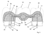
- FIG. 2 schematically shows a finished dental model 24, which comprises a first support structure element 25 in the region of the left corner element 18 (see FIG.
- the support structure member 25, in turn, includes a first insulating portion 21 and an electrically conductive portion 22.
- the insulating portion 21 has been printed out of insulating wax, the conductive portion 22 of conductive wax.
- An electrically conductive region 26 extends along the surface of the electrically conductive section 22.
- the support structure elements correspond in their proportions at least substantially to the stumps of the support teeth shown in dotted lines in FIG. The pores in the interior of the model are not shown graphically.
- the dental model 24 further includes an intermediate structural member 19 in the region of the intermediate member 16 (see Fig. 1).
- An electrically conductive region 28 extends over the surface of the intermediate structural element 19.
- the dental model 24 comprises a second support structure element 17 in the region of the right corner element 20 (see FIG. 1), which comprises an electrically conductive section 27 and an electrically insulating section 15.
- An electrically conductive region 30 extends over the surface of the electrically conductive portion 27.
- the electrically conductive areas 26, 28 and 30 are areas of the surface of the respectively associated electrically conductive portions 22, 23 and 27 and are in the present case conductive due to the conductivity of the electrically conductive portions 22, 23 and 27 itself.
- the Sections 22, 23 and 27 non-conductive and have on their surface only a thin layer of electrically conductive substance.
- the thickness of the electrically conductive surface areas 26, 28, 30 is in this case about 0.2 mm 1 mm. In both cases, the electrically conductive regions 26, 28, 30 in the context of manufacturing accuracy no porosity.
- the three electrically conductive regions 26, 28 and 30 are electrically insulated from one another. Between the conductive region 26 and the electrically conductive region 28 is an electrical insulation 29, between the electrically conductive regions 28 and 30, there is a further electrical insulation 31st
- preparation edges 35a and 35b are provided on the basis of corresponding specifications from the data model which have been modeled there in a preceding work step.
- holes 32, 33, 34 are recessed in the insulating portions 15, 21, engage in the dowel pins or electrodes.
- a first electrode 36 is provided, which engages in the hole 32 and contacts the electrically conductive region 26 of the support structure element 25 via a conductor 37.
- a second electrode 38 engages in the hole 33 and contacted via a conductor 39, the electrically conductive portion 28 of the intermediate structure element 19 and a third electrode 40 according contacted the electrically conductive portion 30 of the support structure element 17 via a conductor 41st
- the dental model is fastened via dowel pins, not shown here, one of which engages in a recess 48 and another in a recess 50 on a likewise not shown model carrier. This completes the production of the rapid prototyping model in the form of the dental model.
- the dental model 24 attached to a model carrier is immersed in a slurry bath such that the electrodes 36, 38, 40 do not come into contact with the slurry.
- the slurry used in the present case is a stabilized mixture of ethanol and alumina powder.
- a liquefying agent is suitable for alumina polyacrylic acid, which causes a high particle charge and at the same time takes over the function of the binder.
- the layer thickness depends in particular on the flowed electrical charge, the selected slip material and the size of the surface of the electrically conductive region 28.
- the layer thickness of the slurry layer is the same at each point of the electrically conductive region 28.
- the size of the surface is calculated from the data model.
- the flowed charge results as the product of the measured electric current and the measured time in which this current has flowed.
- the time can be calculated or at least estimated, after which a ceramic layer of the desired thickness is deposited. This time is up to a few minutes. After this time the current flow is interrupted.
- Fig. 3 a dental model with such a ceramic layer 46 is shown.
- the two other electrically conductive regions 26, 30 are contacted at the same time and deposited on them in the same way ceramic layers.
- the growing together of the respective ceramic layers results in a uniform ceramic layer, namely the later framework.
- ceramic is initially deposited simultaneously on all electrically conductive regions 26, 28, 30, although in the region 28, however, z. B. the voltage can remain applied longer to produce a particularly thick ceramic layer.
- the dental molding receives the desired and characteristic shape and at the same time there is an increase in the transmitted force to be transmitted.
- the ceramic layer in particular the connector 11a, 11b, is chosen stronger, as described, and as a result the deformation is reduced.
- the two last deposited ceramic layers thus have a smaller layer thickness than the first deposited.
- FIG. 5 shows a coalesced ceramic layer 52 on the dental model 24 from which the coping is produced in the course of the subsequent work steps.
- the grown together ceramic layer 52 has different than shown in the figure, a same thickness at each point.
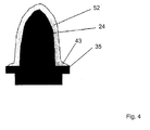
- FIG. 4 schematically shows a dental model 24 with a ceramic layer 52 deposited thereon, which ends at a preparation edge 35. A supernatant 43 is removed for finishing.
- preparation edges 35a, 35b for the limbs of the dental model shown there are shown.
- Preparation edges can be defined and clearly pulled out as a paragraph.
- the limitation of the dental molded part (eg coping cap) in the vertical direction can be visually recognized even after the coating.
- the foot of the tooth stump For example, this root of the stump is so thick that the extension of the surface corresponds to the resulting surface of layer thickness and stump.
- a dental molding (coping or bridge) can be machined up to the required preparation line together with the dental model (eg wax model).
- the data file is preferably processed so that z. B. on the bottom of the dental model at defined locations holes for z. B. dowel pins, or the bottom is shaped so that it fits defined in a model receiving the shape.
- the dental model thus produced can then be locked together with the ceramic layer in a device with a milling cutter, which can then follow the contour based on already existing data. In this way, for example, a ceramic abutment can be produced, which is attached to an implant.
- the surface of the veneer is created according to precisely defined geometries by means of milling.
- the thus finished green product is heated to 150 ° C in the oven on the dental model. This is done in a powder bed.
- the greenware dries and the wax (with a melting point of 54 to 76 ° C) melts. Due to the porosity in the interior of the dental model introduced during rapid prototyping, cracks in the green body can be largely avoided.
- the green compact is sintered at 1300 ° C to 1700 ° C ready, so that a finished dental molding is formed.
- the resulting sintered shrinkage was, as described above, taken into account in the preparation of the dental model, so that the resulting dental molding fits with high accuracy on the master model.
- the burnout of the model and the subsequent sintering is preferably carried out in a powder bed.
- the coated wax model is merely applied to a burn-out pad, it may in rare cases lead to stresses in the green body due to the uneven melting and burning out of the model despite the presence of pores. However, since this is the state in which the ceramic layer has the lowest strength, it may cause cracks. This can be prevented by placing the electrophoretically coated model in a powder bed. As a result, it is not due to gravity and the uneven burning away of the model, to tensions and thus destruction.
- the powder bed thus has the following tasks: a) the powder bed wears the component evenly b) the powder bed absorbs the wax or better dissipates it.
- a binder This may already be added to the slurry, or it is preferably added to the dried framework.
- Exemplary embodiment 2 Production of a ceramic component in the form of a coping or a crown (dental molding) according to a method according to the invention
- a master cast of a single tooth preparation is provided. This is scanned and the data is processed on the PC.
- the volume of the model to be generated is increased in accordance with the decrease in volume during sintering, d. H. the sintering shrinkage compensated.
- a cement gap is considered in the design of the geometry required to cement the copings to the tooth stumps.
- the preparation line is clearly pulled out as a preparation edge.
- the data model is designed so that a dense, 0.2 mm thick surface of the dental model is formed in rapid prototyping, whereas the internal volume of the dental model is constructed as a porous support structure.
- the data model based on STL data is then converted into a dental model via the rapid prototyping (printing) process.
- a) an electrically insulating and (b) a wax made electrically conductive with carbon black particles are used, as described above. The areas are limited by the preparation margin.
- the dental model is prepared by stereolithography from the data model.
- an electrically conductive polymer is applied in layers and cured by means of UV light.
- z. B a device of the company 3d-system type SLA 7000 used.
- the electrically conductive region of the finished dental model is contacted and immersed together with a counter electrode in a Schlickerbad consisting of the slip described above.
- a ceramic layer is completely deposited after a few seconds to a few minutes, depending on the desired layer thickness and the set current flow or voltage.
- the ceramic green body thus produced is dried together with the dental model.
- the ceramic green body of the coping is grinded back defined at the preparation edge with a milling cutter or a grinder. If necessary, additional slip can be applied to change the contour.
- the thermal separation of the model takes place. This takes place already at temperatures between 54 and 76 ° C, since the melting point of the wax is already reached here. Remains of the wax, which have not flowed out as a result of wetting, burn in the further increase in temperature residue.
- the model can be chemically dissolved out.
- the alternatively used rapid prototyping model made of polymer, which was cured by UV radiation, is completely burned out at temperatures up to 550 ° C.
- the sintering of the green body takes place at temperatures of 1300 ° C to 1700 ° C.
- the ceramic particles of the green body sinter together, so that there is a decrease in volume. This volume decrease was previously considered, see above.
- the ceramic framework is, for example, densely sintered or sintered. To increase the strength, additional glass is infiltrated.
- the preserved ceramic coping or crown fits with high accuracy on the master model and thus on the tooth preparation. It has a high density of over 90% and therefore has a high strength. It can not and will not be infiltrated with glass.
- the green body can be sintered at temperatures between 1000 and 1300 ° C. This is associated with only a small decrease in volume but also a remaining high porosity. This porosity can be filled in a subsequent step by glass infiltration. Since the decrease in volume is only slight, in this alternative procedure, the volume of the dental model to be produced is increased only slightly compared to that of the master model.
- This embodiment relates to a gear (micro component) in the form of a spur gear.
- the gear has an internal bore of 150 ⁇ m.
- the generation of the data model for the subsequent rapid prototyping process for the production of the gear takes place on the computer. It takes into account that the ceramic green body produced on the basis of the data model shrinks during sintering. An increase in geometry of the data model is made according to this volume decrease.
- CAD data data model
- a negative of the enlarged by the sintering shrink gear is created on the computer, which is oriented so that its axis is perpendicular to the horizontal. In addition, this negative is divided into horizontal layers of equal thickness.
- This negative is produced by the rapid prototyping method of stereolithography.
- a photo-curing resin is used which has been rendered electrically conductive by the addition of carbon black.
- On a non-electrically conductive substrate is stereolithographically applied a first layer of the mixture of light-curing resin and carbon black and fully cured. Subsequently, the application takes place in layers with subsequent, selective exposure according to the generated data set.
- the substrate is removed from the stereolithography apparatus along with the rapid prototyping model. Subsequently, the rapid prototyping model is freed from the excess, still liquid resin. What remains is the rapid prototyping model in the form of an electrically conductive negative mold of the sintered shrinkage enlarged gear on the non-conductive substrate. This negative mold is electrically contacted and immersed in a ceramic slip.
- the composition of the slurry corresponds to that in the first embodiment.
- the rapid prototyping model (negative) fills with slip and on the electrically conductive surface of the rapid prototyping model, the slip is electrophoretically deposited as a ceramic layer.
- the rapid prototyping model is taken from the sludge bath.
- the rapid prototyping model is clamped in a mill together with the substrate to which the rapid prototyping model is connected.
- the removal of excess deposited slip from the upwardly facing surface of the mold by milling. In this milling process, the through hole of the later gear is generated and produces a good parallelism of the gear sides.
- a subsequent thermal treatment see above, the removal of the mold and the dense sintering of the ceramic microcomponent takes place in the form of the toothed wheel.
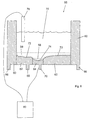
- FIG. 6 shows a rapid prototyping model 55 according to the invention for the electrolytic deposition for the production of a component 56, which is shown in dashed lines. The pores in the interior of the model are not shown graphically.
- the component 56 is flat and has on its one side, which faces downward in FIG. 6, a relief-shaped surface.
- a digital data model of the component is created with the help of a computer. Subsequently, the negative of the relief surface is calculated. Using these geometric data, the Rapid Prototyping Model 55 is manufactured by Ballistic Particle Manufacturing. For this purpose, the wax described above and the above-described mixture of this wax and carbon black are used.
- the rapid prototyping model 55 is circular in cross-section; FIG. 6 shows a cross section parallel to the longitudinal axis of the upright rapid prototyping model 55.
- the rapid prototyping model 55 consists of three sections 60, 62, 64.
- the section 60 is made of electrically non-conductive wax, the two sections 62 and 64 are made of electrically conductive wax.
- the section 60 terminates in a circumferential projection 66 which serves to fix the rapid prototyping model 55 on a model carrier.
- the two sections 62 and 64 run down into peg-like projections 68, 70, which serve the electrical contacting of the two regions 62 and 64, respectively.
- the section 62 has an electrically conductive region 72 on its upwards facing surface.
- section 64 has an electrically conductive region 74 on its upwardly facing surface.
- the rapid prototyping model 55 After production of the rapid prototyping model 55, this is first machined by polishing the electrically conductive regions 72, 74. Subsequently, a solution 76 of a silver salt is first filled into the rapid prototyping model 55. In this solution, an electrode 78 is immersed, which is electrically connected to a power source 80. Subsequently, the power source 80 is electrically connected to the pin-like projection 70 of the portion 64 and a voltage is applied between the electrode 78 and the portion 64. As a result, silver deposits on the electrically conductive region 74 of the section 64. The current flow is maintained until a silver layer of the desired thickness has been deposited on the electrically conductive region 74. The thickness of the silver layer can be determined by the amount of charge that flows as a product of the current and time, and the area of the electrically conductive region 74 that is calculated from the geometric data used to make the rapid prototyping model 55 are based.
- the solution 76 is removed, a copper salt solution filled and the projections 70 and 68 electrically connected together.
- a copper layer is deposited on the electrically conductive region 72 and the deposited silver layer on the electrically conductive region 74.
- the electrolysis is stopped as soon as the desired layer thickness of copper is reached.
- the layer thickness is chosen so large that the component 56 is self-supporting.
- the Rapid Prototyping Model 55 is removed by dissolving the wax with an acid that does not attack the metals. What remains is the component 56, the relief of which represents an exact replica of the relief modeled on the computer.
- This embodiment relates to the production of a galvanized or electrolytically coated plastic part.
- the metallic coating serves functional or optical purposes.
- the design of the plastic part takes place on the computer by means of CAD.
- a plastic base body is constructed using the rapid prototyping method of fused deposition modeling.
- the material used in the rapid prototyping process is a thermoplastic filled with silver.
- the prepared plastic base body is electrically contacted and immersed in a nickel sulfamate-containing electrolyte in which the counter electrode is already located. After applying a voltage between the counter electrode and the rapid prototyping model, nickel deposits on the electrically conductive areas of the surface of the rapid prototyping model. It is built up a nickel layer of about 100 microns thick. The control of the layer thickness takes place over the time or measurement of the current flow. Aftertreatment of the new surface thus produced is possible, for example by polishing, depending on the application.
Landscapes
- Engineering & Computer Science (AREA)
- Chemical & Material Sciences (AREA)
- Materials Engineering (AREA)
- Health & Medical Sciences (AREA)
- Manufacturing & Machinery (AREA)
- Optics & Photonics (AREA)
- Physics & Mathematics (AREA)
- Mechanical Engineering (AREA)
- Life Sciences & Earth Sciences (AREA)
- Oral & Maxillofacial Surgery (AREA)
- Public Health (AREA)
- Veterinary Medicine (AREA)
- General Health & Medical Sciences (AREA)
- Animal Behavior & Ethology (AREA)
- Epidemiology (AREA)
- Dentistry (AREA)
- Molecular Biology (AREA)
- Ceramic Engineering (AREA)
- Civil Engineering (AREA)
- Composite Materials (AREA)
- Structural Engineering (AREA)
- Manufacture Of Porous Articles, And Recovery And Treatment Of Waste Products (AREA)
Applications Claiming Priority (1)
| Application Number | Priority Date | Filing Date | Title |
|---|---|---|---|
| DE102004052365A DE102004052365B4 (de) | 2004-10-28 | 2004-10-28 | Verfahren zur Herstellung eines Rapid-Prototyping-Modells, eines Grünlings, eines Keramikbauteils und eines metallischen Bauteils |
Publications (2)
| Publication Number | Publication Date |
|---|---|
| EP1652655A2 true EP1652655A2 (fr) | 2006-05-03 |
| EP1652655A3 EP1652655A3 (fr) | 2006-07-12 |
Family
ID=35601906
Family Applications (1)
| Application Number | Title | Priority Date | Filing Date |
|---|---|---|---|
| EP05109816A Withdrawn EP1652655A3 (fr) | 2004-10-28 | 2005-10-21 | Méthode de production d'un modèle par prototypage rapide comprenant des domaines électriquement conducteurs |
Country Status (4)
| Country | Link |
|---|---|
| US (1) | US20060118990A1 (fr) |
| EP (1) | EP1652655A3 (fr) |
| JP (1) | JP2006183134A (fr) |
| DE (1) | DE102004052365B4 (fr) |
Cited By (5)
| Publication number | Priority date | Publication date | Assignee | Title |
|---|---|---|---|---|
| DE102008031926A1 (de) * | 2008-07-08 | 2010-01-14 | Bego Medical Gmbh | Verfahren zum schichtweisen Herstellen stark geneigter Flächen |
| EP2551092A1 (fr) * | 2011-07-28 | 2013-01-30 | United Technologies Corporation | Procédé de fabrication rapide |
| CN104400879A (zh) * | 2014-10-30 | 2015-03-11 | 江苏恒天先进制造科技有限公司 | 一种3d成型陶瓷模具制作的方法 |
| US20170296311A1 (en) * | 2014-09-29 | 2017-10-19 | Gc Corporation | Method for manufacturing dental prosthesis |
| CN116476193A (zh) * | 2023-03-24 | 2023-07-25 | 上海数造机电科技股份有限公司 | 基于静电吸附的陶瓷3d打印构建平台、方法及系统 |
Families Citing this family (37)
| Publication number | Priority date | Publication date | Assignee | Title |
|---|---|---|---|---|
| DE102006023369A1 (de) * | 2005-06-03 | 2006-12-07 | Fraunhofer-Gesellschaft zur Förderung der angewandten Forschung e.V. | Verfahren zur Herstellung eines Gegenstands mit mindestens zwei beweglichen Bauteilen |
| DE102007014985A1 (de) | 2007-03-28 | 2008-10-02 | Aepsilon Rechteverwaltungs Gmbh | Verfahren zum Herstellen von Zahnersatzteilen, Verfahren zum Erstellen eines Datensatzes und computerlesbares Medium |
| EP2233449B1 (fr) * | 2009-03-27 | 2014-12-17 | Ivoclar Vivadent AG | Utilisation d'une barbotine pour la fabrication de céramiques dentaires à l'aide du procédé d'impression par injection de matière thermoplastique |
| WO2012140658A2 (fr) * | 2011-04-10 | 2012-10-18 | Objet Ltd. | Système et procédé pour l'impression couche par couche d'un objet avec soutien |
| AU2012357646B2 (en) | 2011-12-24 | 2016-11-10 | Zydex Pty Ltd | Method and apparatus for making an object |
| US9903212B2 (en) * | 2013-07-30 | 2018-02-27 | Siemens Aktiengesellschaft | Mechanical joining using additive manufacturing process |
| US9562632B1 (en) * | 2013-10-11 | 2017-02-07 | United Services Automobile Association (Usaa) | Fabricating conduits |
| US9937673B1 (en) | 2013-11-21 | 2018-04-10 | United Services Automobile Association (Usaa) | Plumbing systems with integrated leak detection and repair |
| DE102013111387A1 (de) * | 2013-10-15 | 2015-04-16 | Renfert Gmbh | Dentaldruckvorrichtung |
| WO2015070165A1 (fr) * | 2013-11-11 | 2015-05-14 | Mosher Brent | Retrait d'une structure de support pour des pièces imprimées en 3d |
| US20170066186A1 (en) * | 2014-02-21 | 2017-03-09 | Laing O'rourke Australia Pty Limited | Method for fabricating a composite construction element |
| US10799952B2 (en) | 2015-06-04 | 2020-10-13 | The Regents Of The University Of California | Selective laser sintering using functional inclusions dispersed in the matrix material being created |
| DE102015223240A1 (de) * | 2015-11-24 | 2017-05-24 | Sgl Carbon Se | Kohlenstoff-Metall Verbundwerkstoff |
| US10118217B2 (en) | 2015-12-17 | 2018-11-06 | General Electric Company | Method and assembly for forming components having internal passages using a jacketed core |
| US9968991B2 (en) | 2015-12-17 | 2018-05-15 | General Electric Company | Method and assembly for forming components having internal passages using a lattice structure |
| US10099276B2 (en) | 2015-12-17 | 2018-10-16 | General Electric Company | Method and assembly for forming components having an internal passage defined therein |
| US10046389B2 (en) | 2015-12-17 | 2018-08-14 | General Electric Company | Method and assembly for forming components having internal passages using a jacketed core |
| US9987677B2 (en) | 2015-12-17 | 2018-06-05 | General Electric Company | Method and assembly for forming components having internal passages using a jacketed core |
| US9579714B1 (en) | 2015-12-17 | 2017-02-28 | General Electric Company | Method and assembly for forming components having internal passages using a lattice structure |
| US10137499B2 (en) | 2015-12-17 | 2018-11-27 | General Electric Company | Method and assembly for forming components having an internal passage defined therein |
| US10099284B2 (en) | 2015-12-17 | 2018-10-16 | General Electric Company | Method and assembly for forming components having a catalyzed internal passage defined therein |
| US10099283B2 (en) | 2015-12-17 | 2018-10-16 | General Electric Company | Method and assembly for forming components having an internal passage defined therein |
| US10926464B2 (en) | 2016-04-15 | 2021-02-23 | Hewlett-Packard Development Company, L.P. | Material sets |
| US10286450B2 (en) | 2016-04-27 | 2019-05-14 | General Electric Company | Method and assembly for forming components using a jacketed core |
| US10335853B2 (en) | 2016-04-27 | 2019-07-02 | General Electric Company | Method and assembly for forming components using a jacketed core |
| DE102016109447A1 (de) * | 2016-05-23 | 2017-12-07 | Bredent Gmbh & Co. Kg | Keramikschale zur Herstellung von Zahnersatz und Verfahren zur Herstellung einer Keramikschale für Zahnersatz |
| WO2017202869A1 (fr) | 2016-05-23 | 2017-11-30 | Bredent Gmbh & Co. Kg | Procédé de fabrication de prothèse dentaire |
| GB2552312B (en) | 2016-07-14 | 2018-10-31 | Cat International Ltd | Ceramic objects and methods for manufacturing the same |
| EP3512676A4 (fr) | 2016-09-15 | 2020-02-12 | Mantle Inc. | Système et procédé de fabrication additive métallique |
| WO2018194564A1 (fr) | 2017-04-18 | 2018-10-25 | Hewlett-Packard Development Company, L.P. | Augmentation de la conductivité électrique à des emplacements sélectionnés d'un objet 3d |
| DE102017110361A1 (de) * | 2017-05-12 | 2018-11-15 | Psc Technologies Gmbh | Verfahren zur Herstellung von siliciumcarbidhaltigen Strukturen |
| US10900136B2 (en) | 2017-07-18 | 2021-01-26 | Honeywell International Inc. | Additive-based electroforming manufacturing methods and metallic articles produced thereby |
| DE102018203750B4 (de) * | 2018-03-13 | 2024-07-11 | Fraunhofer-Gesellschaft zur Förderung der angewandten Forschung e.V. | Verfahren zur Herstellung eines Bauteils, durch dessen Inneres mindestens ein Mikrokanal geführt ist |
| US20190376199A1 (en) * | 2018-06-11 | 2019-12-12 | The Boeing Company | Rapid tooling using meltable substrate and electrodeposition |
| CN108751951A (zh) * | 2018-06-14 | 2018-11-06 | 长沙鹏登生物陶瓷有限公司 | 一种3d打印义齿陶瓷材料及制备方法 |
| US12172373B2 (en) * | 2019-11-26 | 2024-12-24 | Lubbe Steven | Devices, systems, and methods for 3D printing |
| CN112642502A (zh) * | 2020-12-19 | 2021-04-13 | 电子科技大学中山学院 | 一种数字微流控芯片系统的制造和计算方法 |
Family Cites Families (14)
| Publication number | Priority date | Publication date | Assignee | Title |
|---|---|---|---|---|
| WO1991004798A1 (fr) * | 1989-09-29 | 1991-04-18 | 3D Systems, Inc. | Procedes de revetement de parties stereolithographiques |
| US5738817A (en) * | 1996-02-08 | 1998-04-14 | Rutgers, The State University | Solid freeform fabrication methods |
| US5782589A (en) * | 1996-06-17 | 1998-07-21 | Cole; John M. | Milling cutter |
| US6200508B1 (en) * | 1996-10-25 | 2001-03-13 | Massachusetts Institute Of Technology | Method of fabricating electro-mechanical devices by multilayer deposition |
| US5919347A (en) * | 1997-04-23 | 1999-07-06 | Cerel (Ceramic Technologies) Ltd. | Method of electrophoretic deposition of laminated green bodies |
| US6821462B2 (en) * | 1998-07-10 | 2004-11-23 | Jeneric/Pentron, Inc. | Mass production of shells and models for dental restorations produced by solid free-form fabrication methods |
| US6363606B1 (en) * | 1998-10-16 | 2002-04-02 | Agere Systems Guardian Corp. | Process for forming integrated structures using three dimensional printing techniques |
| US6410086B1 (en) * | 1999-11-26 | 2002-06-25 | Cerel (Ceramic Technologies) Ltd. | Method for forming high performance surface coatings and compositions of same |
| US6652256B2 (en) * | 2000-10-27 | 2003-11-25 | Dorsey D. Coe | Three-dimensional model colorization during model construction from computer aided design data |
| GB0103752D0 (en) * | 2001-02-15 | 2001-04-04 | Vantico Ltd | Three-Dimensional printing |
| US20040005374A1 (en) * | 2002-05-16 | 2004-01-08 | Subhash Narang | Creating objects through X and Z movement of print heads |
| AT411816B (de) * | 2002-07-19 | 2004-06-25 | Mediceram Chirurgische Implant | Verfahren zur herstellung einer belastbaren struktur aus oxidkeramik, insbesondere aus zirkondioxid |
| DE10311446A1 (de) * | 2002-09-21 | 2004-04-01 | Degussa Ag | Polymerpulver für SIV-Verfahren |
| MXPA05004784A (es) * | 2002-11-05 | 2005-11-04 | Wolz Stefan | Metodo para producir elementos dentales enteramente ceramicos con forma espacial predeterminada mediante electroforesis. |
-
2004
- 2004-10-28 DE DE102004052365A patent/DE102004052365B4/de not_active Expired - Fee Related
-
2005
- 2005-10-21 EP EP05109816A patent/EP1652655A3/fr not_active Withdrawn
- 2005-10-28 JP JP2005313766A patent/JP2006183134A/ja active Pending
- 2005-10-28 US US11/260,303 patent/US20060118990A1/en not_active Abandoned
Cited By (8)
| Publication number | Priority date | Publication date | Assignee | Title |
|---|---|---|---|---|
| DE102008031926A1 (de) * | 2008-07-08 | 2010-01-14 | Bego Medical Gmbh | Verfahren zum schichtweisen Herstellen stark geneigter Flächen |
| EP2551092A1 (fr) * | 2011-07-28 | 2013-01-30 | United Technologies Corporation | Procédé de fabrication rapide |
| US20170296311A1 (en) * | 2014-09-29 | 2017-10-19 | Gc Corporation | Method for manufacturing dental prosthesis |
| EP3202367A4 (fr) * | 2014-09-29 | 2018-05-23 | GC Corporation | Procédé de fabrication de prothèse dentaire |
| US10603142B2 (en) | 2014-09-29 | 2020-03-31 | Gc Corporation | Method for manufacturing dental prosthesis |
| CN104400879A (zh) * | 2014-10-30 | 2015-03-11 | 江苏恒天先进制造科技有限公司 | 一种3d成型陶瓷模具制作的方法 |
| CN116476193A (zh) * | 2023-03-24 | 2023-07-25 | 上海数造机电科技股份有限公司 | 基于静电吸附的陶瓷3d打印构建平台、方法及系统 |
| CN116476193B (zh) * | 2023-03-24 | 2024-01-05 | 上海数造机电科技股份有限公司 | 基于静电吸附的陶瓷3d打印构建平台、方法及系统 |
Also Published As
| Publication number | Publication date |
|---|---|
| DE102004052365B4 (de) | 2010-08-26 |
| JP2006183134A (ja) | 2006-07-13 |
| EP1652655A3 (fr) | 2006-07-12 |
| US20060118990A1 (en) | 2006-06-08 |
| DE102004052365A1 (de) | 2006-05-04 |
Similar Documents
| Publication | Publication Date | Title |
|---|---|---|
| DE102004052365B4 (de) | Verfahren zur Herstellung eines Rapid-Prototyping-Modells, eines Grünlings, eines Keramikbauteils und eines metallischen Bauteils | |
| EP1652491A1 (fr) | Procédé de fabrication d'un modèle dentaire ainsi qu'un élément de restauration, un modèle dentaire et l'utilisation d'une imprimante 3D et d'un kit | |
| EP1021997B2 (fr) | Procédé de manufacture de prothèses dentaires et d'accessoires orthodontiques | |
| DE69910384T2 (de) | Verfahren zur herstellung von feuerfesten formkörpern | |
| EP3074208B1 (fr) | Procédé d'impression 3d à barbotine | |
| EP1372521B1 (fr) | Procede de production de pieces moulees dentaires en ceramique pleine | |
| EP2714354B1 (fr) | Procédé pour produire un corps moulé et dispositif correspondant | |
| DE102008031925B4 (de) | Duales Herstellungsverfahren für Kleinserienprodukte | |
| EP0909234B1 (fr) | Procede de fabrication d'un corps en trois dimensions | |
| DE102011117005B4 (de) | Verfahren zur Herstellung eines keramischen Formkörpers | |
| EP1250895B1 (fr) | Méthode pour obtenir des pièces dentaires en céramique | |
| EP1940575A1 (fr) | Procede de fabrication par couches avec commande de granulometrie | |
| EP3687763A1 (fr) | Pièces façonnées imprimées en 3d à partir de plus d'un matériau silicone | |
| EP1280475B1 (fr) | Procede de production de sous-structures en ceramique pleine, notamment en alumine, en technique dentaire | |
| WO2021078740A2 (fr) | Procédé de réalisation d'un moule de coulée à froid et utilisation d'un moule de coulée à froid pour la réalisation de pièces moulées, notamment d'une prothèse dentaire | |
| DE102014111559B4 (de) | Verfahren zur Herstellung von Schichtenfolgen und Formkörpern aus einer Anzahl von Schichten | |
| DE102005038074A1 (de) | Verfahren zur Herstellung metallischer Bauteile, entsprechende metallische Bauteile sowie Kit zur Durchführung des Verfahrens | |
| DE102017124124A1 (de) | Verfahren zur additiven Fertigung eines Bauteils sowie Vorrichtung zur Durchführung des Verfahrens | |
| WO2022022763A1 (fr) | Procédé de production d'un article façonné en 3d et dispositif utilisant un plateau perforé | |
| DE10115818A1 (de) | Verwendung keramischer Schlicker zur Herstellung vollkeramischer Dentalformteile | |
| EP3352702B1 (fr) | Procédé de réalisation de restaurations dentaires à l'aide d'une poudre dentaire | |
| EP3173392A1 (fr) | Procédé et dispositif de fabrication d'éléments en céramique | |
| EP4477417A1 (fr) | Procédé de fabrication d'une restauration dentaire | |
| DE102010028693A1 (de) | Verfahren zur Herstellung eines Zahnersatzteils und Zahnersatzteil | |
| DE102018200509A1 (de) | Verfahren zur Herstellung von Wendeln |
Legal Events
| Date | Code | Title | Description |
|---|---|---|---|
| PUAI | Public reference made under article 153(3) epc to a published international application that has entered the european phase |
Free format text: ORIGINAL CODE: 0009012 |
|
| AK | Designated contracting states |
Kind code of ref document: A2 Designated state(s): AT BE BG CH CY CZ DE DK EE ES FI FR GB GR HU IE IS IT LI LT LU LV MC NL PL PT RO SE SI SK TR |
|
| AX | Request for extension of the european patent |
Extension state: AL BA HR MK YU |
|
| PUAL | Search report despatched |
Free format text: ORIGINAL CODE: 0009013 |
|
| AK | Designated contracting states |
Kind code of ref document: A3 Designated state(s): AT BE BG CH CY CZ DE DK EE ES FI FR GB GR HU IE IS IT LI LT LU LV MC NL PL PT RO SE SI SK TR |
|
| AX | Request for extension of the european patent |
Extension state: AL BA HR MK YU |
|
| AKX | Designation fees paid | ||
| STAA | Information on the status of an ep patent application or granted ep patent |
Free format text: STATUS: THE APPLICATION IS DEEMED TO BE WITHDRAWN |
|
| 18D | Application deemed to be withdrawn |
Effective date: 20070113 |
|
| REG | Reference to a national code |
Ref country code: DE Ref legal event code: 8566 |