EP1652736A1 - Véhicule avec ensemble de protection deployable contre le retournement de véhicule - Google Patents
Véhicule avec ensemble de protection deployable contre le retournement de véhicule Download PDFInfo
- Publication number
- EP1652736A1 EP1652736A1 EP05270066A EP05270066A EP1652736A1 EP 1652736 A1 EP1652736 A1 EP 1652736A1 EP 05270066 A EP05270066 A EP 05270066A EP 05270066 A EP05270066 A EP 05270066A EP 1652736 A1 EP1652736 A1 EP 1652736A1
- Authority
- EP
- European Patent Office
- Prior art keywords
- roll bar
- trim
- motor vehicle
- pin
- item
- Prior art date
- Legal status (The legal status is an assumption and is not a legal conclusion. Google has not performed a legal analysis and makes no representation as to the accuracy of the status listed.)
- Granted
Links
- 230000000712 assembly Effects 0.000 title description 2
- 238000000429 assembly Methods 0.000 title description 2
- 229910000639 Spring steel Inorganic materials 0.000 claims description 3
- 239000004033 plastic Substances 0.000 claims description 3
- 229920003023 plastic Polymers 0.000 claims description 3
- 239000011521 glass Substances 0.000 abstract description 4
- 239000000463 material Substances 0.000 abstract description 3
- 238000004080 punching Methods 0.000 abstract 1
- 239000012634 fragment Substances 0.000 description 2
- UONOETXJSWQNOL-UHFFFAOYSA-N tungsten carbide Chemical compound [W+]#[C-] UONOETXJSWQNOL-UHFFFAOYSA-N 0.000 description 2
- 229910000831 Steel Inorganic materials 0.000 description 1
- 239000000853 adhesive Substances 0.000 description 1
- 230000001070 adhesive effect Effects 0.000 description 1
- 239000003822 epoxy resin Substances 0.000 description 1
- 239000010985 leather Substances 0.000 description 1
- 229920000647 polyepoxide Polymers 0.000 description 1
- 230000000717 retained effect Effects 0.000 description 1
- 239000010959 steel Substances 0.000 description 1
Images


Classifications
-
- B—PERFORMING OPERATIONS; TRANSPORTING
- B60—VEHICLES IN GENERAL
- B60R—VEHICLES, VEHICLE FITTINGS, OR VEHICLE PARTS, NOT OTHERWISE PROVIDED FOR
- B60R21/00—Arrangements or fittings on vehicles for protecting or preventing injuries to occupants or pedestrians in case of accidents or other traffic risks
- B60R21/02—Occupant safety arrangements or fittings, e.g. crash pads
- B60R21/13—Roll-over protection
Definitions
- This invention relates to motor vehicles incorporating deployable roll bar assemblies and particularly to convertible motor vehicles having a rear window made of glass.
- Applicants co-pending application EP 04254627.7 describes a deployable roll bar assembly capable of shattering a vehicle's rear window on deployment.
- the assembly includes a hollow inverted U-shaped roll bar which is retained in a housing by a spring-loaded mechanism.
- the housing may be fixed to a rear bulkhead of the vehicle.
- the bar is fitted with one or two pins on its upper surface.
- the pins are fixed to the roll bar by means of a threaded joint.
- a protruding part of the pin may have a conical, frusto-conical, or domed shape. Such shapes have been found to break a glass window satisfactorily, causing it to shatter into small pieces.
- the protruding part of the pin is made from a hard material eg.. tungsten carbide.
- the spring-loaded mechanism When a vehicle motion sensor detects that rollover of the vehicle is imminent, the spring-loaded mechanism is released. Consequently, the roll bar is rapidly deployed upwards towards the rear window,. whereupon at least one of the pins strikes the window causing it to shatter into many fragments . Once the roll bar is deployed to its fullest extent, it locks in position just beyond the roof line and clear of the head of any occupants, thus affording the necessary protection.
- the assembly described in EP 04254627.7 further provides an item of trim, which may be frangible or removable, and located over the roll bar's upper surface to prevent the pins from causing any damage to passengers or items of clothing or luggage.
- trim which may be frangible or removable
- the roll bar is required to break through the trim item as it progresses on its way towards the rear window.
- energy is expended in breaking the trim item.
- the roll bar is required to push the trim item out of the way as it progresses towards the rear window.
- a motor vehicle incorporating a deployable roll bar assembly
- a deployable roll bar having a protruding pin on an upper surface thereof, a first trim item fixed with respect to the motor vehicle for supporting a second trim item which comprises a cover for an upper portion of the roll bar and being movable with respect to the motor vehicle, and incorporating an orifice for receiving the pin and at least one spring-loaded circular clip for location around the roll bar's upper portion, the clip being held under tension by the relative position of the first trim item and the second trim item, whereby in use, on deployment off the roll bar, the upper portion thereof moves towards the second trim item until the pin protrudes through the orifice and the tension on the spring clip is relieved, whereupon the clip clamps around the roll bar and the cover continues to move with the roll bar towards a rear window of the vehicle.
- the pin may have a conical or frusto-conical form or may be dome-shaped.
- the pin is located on the roll bar so that it is closer to the outboard side of the vehicle rather than the inboard side in order to ensure that on deployment, the pin makes contact with the rear window before any other part of the bar.
- the second trim item is provided with two spring-loaded circular clips, one either side of the orifice, to aid stability of the item.
- the second trim item may be made from plastics and a have its outer surface covered with leather or a similar material.
- the clip is made from spring steel and may be bonded and then ultrasonically welded to the second trim item.
- the assembly may be located on the rear bulkhead of the vehicle.
- a hollow, inverted U-shaped roll bar 1 co-operates with a roll bar release mechanism 2 (whose housing alone is shown in Fig. 1 for the sake of clarity).
- the release mechanism is a spring-loaded arrangement.
- the spring-loaded arrangement could be replaced with a pyrotechnic mechanism.
- the release mechanism is activated by a release device 3 which in this example is a solenoid switch. (As an alternative, a pyrotechnic actuator could be used).
- the roll bar 1, spring-loaded arrangement 2 and solenoid switch 3 operate in a known manner ie. when a remotely-generated trigger signal is received by the solenoid switch 3, the switch activates the release mechanism 2 and as a consequence, the roll bar 1 is deployed upwards and out of the housing 2 (in the direction off arrow A).
- Conventional locking means prevent the roll bar 1 from moving any further or from being pushed back into the housing by any external force once the roll bar 1 has reached its fully deployed position.
- the roll bar 1 is fitted with a pin 4 on its upper surface and closer to one shoulder of the roll bar than the other.
- the pin 4 consists of a threaded portion, and integral lock nut and an end portion having a conical form.
- the threaded portion co-operates with a tapped hole in the upper surface of the roll bar.
- the threaded portion and lock nut are made of steel and the end portion is composed of tungsten carbide and bonded to the lock nut using a suitable epoxy resin adhesive.
- Fig.2 shows a plastics cover 5 (shown as being transparent, for the sake of clarity) which fits over the roll bar 1.
- the cover 5 has an inverted U-channel shape and incorporates a hole 6 aligned with the pin 4.
- Two spring-loaded circular clips 7, 8, made from spring steel, are positioned either side of the hole 6 and are bonded and ultrasonically to welded to the inner surface of the cover 5.
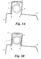
- Cross-sectional views 3A, 3B show the positions off the pin 4 and the clip 8 prior to the deployment of the roll bar 1.
- the cover 5 rests on trim 9 connected to the bulkhead.
- the cover is supported at points 10 and 11 so that the pin 4 does not protrude through the hole 6 (and so does not present a hazard to vehicle occupants) and so that the clips grip the roll bar 1 but do not completely close around it, therefore being held under tension.
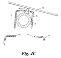
- Figs. 4A 4B and 4C illustrate relative movement off the components of the assembly on the deployment of the roll bar 1.
- the roll bar 1 moves upwards, towards the inner surface of the cover 5.
- the pin 4 protrudes through the hole 6 (Fig. 4A).
- the clips 7, 8 snap into place around the bar 1 (Fig.4B), releasing stored energy.
- the bar 1 and cover 5 move together upwards and away from the support points 10, 11 and pin 4 can strike the rear window 12 of a vehicle (Fig. 4C).
- Fig. 5A the roll bar arrangement of Figs. 1 to 4 is shown incorporated in a convertible vehicle 13 which includes a removable or folding roof 14 incorporating rear window 12 made of glass, a seat 15 and rear bulkhead 16. The rest of the vehicle is omitted for the sake of clarity.
- the roll-bar arrangement of Figs 1 to 4 is secured to the rear bulkhead 9 behind the seat 15.
- a vehicle motion sensor 17, of conventional design whose electrical output (not shown) is connected to the solenoid switch 3.
- the cover 5 is positioned over the roll bar and supported on the bulkhead 16, hiding the roll bar 1 from view whilst in its un-deployed position.
- the vehicle motion sensor 17 When the vehicle motion sensor 17 detects that rollover of the vehicle 13 is imminent, it transmits a trigger signal to the solenoid switch 3 which in turn, activates the release mechanism 2. Consequently, the roll bar 1 and cover 5 are rapidly deployed upwards (in the direction of arrow B). As the roll bar 1 deploys, the pin 4 protrudes through the hole in the cover and finally strikes the window causing the latter to shatter into many fragments 18. Once the roll bar 1 is deployed to its fullest extent, it locks in position just beyond the roof line as defined by the profile of the rear window 12 and clear of the head of any occupant of the seat 15, thus affording the necessary protection.
Landscapes
- Engineering & Computer Science (AREA)
- Mechanical Engineering (AREA)
- Body Structure For Vehicles (AREA)
Applications Claiming Priority (1)
| Application Number | Priority Date | Filing Date | Title |
|---|---|---|---|
| GBGB0423709.5A GB0423709D0 (en) | 2004-10-26 | 2004-10-26 | Motor vehicles incorporating deployable roll bar assemblies |
Publications (2)
| Publication Number | Publication Date |
|---|---|
| EP1652736A1 true EP1652736A1 (fr) | 2006-05-03 |
| EP1652736B1 EP1652736B1 (fr) | 2008-09-10 |
Family
ID=33485191
Family Applications (1)
| Application Number | Title | Priority Date | Filing Date |
|---|---|---|---|
| EP05270066A Expired - Lifetime EP1652736B1 (fr) | 2004-10-26 | 2005-10-12 | Véhicule avec ensemble de protection deployable contre le retournement de véhicule |
Country Status (4)
| Country | Link |
|---|---|
| US (1) | US7198294B2 (fr) |
| EP (1) | EP1652736B1 (fr) |
| DE (1) | DE602005009629D1 (fr) |
| GB (1) | GB0423709D0 (fr) |
Cited By (7)
| Publication number | Priority date | Publication date | Assignee | Title |
|---|---|---|---|---|
| JP2006176117A (ja) * | 2004-12-22 | 2006-07-06 | Dr Ing H C F Porsche Ag | 可動式ルーフ及び張り出し可能な転倒時保護構造を有する車両 |
| EP1900577A1 (fr) * | 2006-02-14 | 2008-03-19 | Automotive Group ISE Innomotive Systems Europe GmbH | Dispositif d'arceau pour véhicule a deploiement automatique avec un arceau de sécurité avec résistant à l'usure |
| EP2070775A1 (fr) * | 2007-12-13 | 2009-06-17 | ISE Automotive GmbH | Dispositif d'arceau de sécurité doté d'un dispositif de rupture de vitre |
| DE102007061014A1 (de) * | 2007-12-18 | 2009-06-25 | Dr. Ing. H.C. F. Porsche Aktiengesellschaft | Kraftfahrzeug mit einer verlagerbaren Dachanordnung und einem Überrollschutzelement |
| EP2072344A3 (fr) * | 2007-12-13 | 2009-11-25 | ISE Automotive GmbH | Dispositif de protection contre les tonneaux doté d'un dispositif d'ouverture |
| ITRM20080569A1 (it) * | 2008-10-24 | 2010-04-24 | Maserati Spa | Dispositivo per la rottura del lunotto posteriore di un veicolo. |
| GB2471004A (en) * | 2009-06-10 | 2010-12-15 | Porsche Ag | Motor vehicle having an adjustable roof and a deployable rollover protection element |
Families Citing this family (20)
| Publication number | Priority date | Publication date | Assignee | Title |
|---|---|---|---|---|
| DE20303691U1 (de) * | 2003-03-07 | 2004-07-15 | Ise Innomotive Systems Europe Gmbh | Überrollschutzvorrichtung |
| DE10358774A1 (de) * | 2003-12-12 | 2005-07-14 | Brose Schließsysteme GmbH & Co.KG | Haltevorrichtung für eine Fahrzeugsicherheitseinrichtung |
| DE102005029451A1 (de) * | 2005-06-24 | 2007-01-04 | Wilhelm Karmann Gmbh | Kraftfahrzeug mit einem Überrollschutzsystem |
| US7401851B2 (en) * | 2005-12-28 | 2008-07-22 | Nissan Design America, Inc. | Stowable passenger seat with roll bar |
| US7384067B2 (en) * | 2006-01-06 | 2008-06-10 | Autoliv Asp, Inc. | Rollover protection for motor vehicles |
| US20070199759A1 (en) * | 2006-02-24 | 2007-08-30 | Dan Tang | Device And Method For Reinforcing A Vehicle Having A Pillared Roof |
| US7585023B2 (en) * | 2006-02-24 | 2009-09-08 | Ford Global Technologies, Llc | Support structure for roof reinforcement |
| US20070200330A1 (en) * | 2006-02-24 | 2007-08-30 | Dan Tang | Occupant Safety Device For Roof Reinforcement |
| US20070200331A1 (en) * | 2006-02-24 | 2007-08-30 | Dan Tang | Occupant Safety Device For Roof Reinforcement |
| US7654569B2 (en) * | 2006-04-13 | 2010-02-02 | Autoliv Asp, Inc. | Rollover protection system for a motor vehicle and related method |
| DE102007029097B4 (de) * | 2007-06-21 | 2009-06-18 | Ise Automotive Gmbh | Überrollschutzsystem für Kraftfahrzeuge mit zumindest einem pyrotechnisch aufstellbaren Überrollkörper |
| JP5235346B2 (ja) * | 2007-07-18 | 2013-07-10 | 日野自動車株式会社 | 車両のヘッドレスト構造 |
| DE102008005451B4 (de) * | 2008-01-22 | 2019-05-02 | Dr. Ing. H.C. F. Porsche Aktiengesellschaft | Überrollschutzsystem für ein Kraftfahrzeug |
| US7896422B2 (en) * | 2009-03-12 | 2011-03-01 | Magna Car Top Systems Gmbh | Convertible top with skylight |
| DE102009034662A1 (de) * | 2009-07-24 | 2011-01-27 | Dr. Ing. H.C. F. Porsche Aktiengesellschaft | Geschlossener Personenkraftwagen mit einer Überrollschutzeinrichtung |
| US8186187B2 (en) * | 2009-10-02 | 2012-05-29 | Stanton Concepts, L.L.C. | Dual custody privacy padlock |
| DE102012112538A1 (de) * | 2012-12-18 | 2014-06-18 | Dr. Ing. H.C. F. Porsche Aktiengesellschaft | Anordnung für ein Kraftfahrzeug |
| DE102015103308A1 (de) * | 2015-03-06 | 2016-09-08 | Dr. Ing. H.C. F. Porsche Aktiengesellschaft | Überrollschutzelement |
| DE102015109859A1 (de) * | 2015-06-19 | 2016-12-22 | Dr. Ing. H.C. F. Porsche Aktiengesellschaft | Überrollschutzsystem für ein Kraftfahrzeug |
| EP4644117A1 (fr) * | 2024-05-02 | 2025-11-05 | Kuraray Europe GmbH | Verre feuilleté pour systèmes de protection déployables contre le retournement |
Citations (6)
| Publication number | Priority date | Publication date | Assignee | Title |
|---|---|---|---|---|
| US5205585A (en) * | 1989-08-18 | 1993-04-27 | Alfred Teves Gmbh | Occupant safety device for automotive vehicles |
| EP0623492A1 (fr) * | 1993-05-03 | 1994-11-09 | Bayerische Motoren Werke Aktiengesellschaft | Dispositif à arceau de sécurité pour un véhicule automobile |
| US5458396A (en) * | 1989-02-06 | 1995-10-17 | Audi Ag | Roll bar for convertible motor vehicles |
| US5655791A (en) * | 1993-08-03 | 1997-08-12 | Itt Automotive Europe Gmbh | Roll bar equipment with inner guide and outer guide |
| US6179327B1 (en) * | 1998-04-22 | 2001-01-30 | Blechformwerke Bernsbach Gmbh | Roll bar |
| EP1510412A1 (fr) * | 2003-08-27 | 2005-03-02 | Ford Global Technologies, LLC | Agencement d'arceau de protéction pour un véhicule |
Family Cites Families (15)
| Publication number | Priority date | Publication date | Assignee | Title |
|---|---|---|---|---|
| DE3410676C1 (de) * | 1984-03-23 | 1985-07-25 | Daimler-Benz Ag, 7000 Stuttgart | UEberrollschutzvorrichtung fuer einen Kraftwagen |
| DE3712940C1 (de) * | 1987-04-16 | 1988-09-01 | Daimler Benz Ag | UEberrollbuegel fuer Kraftwagen |
| DE3922509A1 (de) * | 1989-07-08 | 1991-01-17 | Daimler Benz Ag | Kopfstuetze fuer ruecksitze |
| DE3925515C1 (fr) * | 1989-08-02 | 1991-01-31 | Bayerische Motoren Werke Ag, 8000 Muenchen, De | |
| US5626361A (en) * | 1993-05-03 | 1997-05-06 | Bayerische Motoren Werke Ag | Roll-over protection arrangement for a motor vehicle |
| DE4426733A1 (de) | 1993-08-19 | 1995-02-23 | Volkswagen Ag | Im Überschlagsfall durch Airbagaktivierung aufstellbarer Überrollbügel |
| DE19650593A1 (de) * | 1996-12-06 | 1998-06-10 | Bayerische Motoren Werke Ag | Überrollschutzsystem für einen Personenkraftwagen |
| DE29807322U1 (de) * | 1998-04-22 | 1998-10-22 | Blechformwerke Bernsbach GmbH, 08315 Bernsbach | Überrollbügel |
| DE19834689A1 (de) * | 1998-07-31 | 2000-02-03 | Bayerische Motoren Werke Ag | Überrollschutz-System für ein Kraftfahrzeug, insbesondere für ein Cabriolet |
| DE19906912C1 (de) * | 1999-02-19 | 2000-04-13 | Ise Gmbh | Überroll-Schutzsystem für Kraftfahrzeuge |
| FR2791021B1 (fr) * | 1999-03-16 | 2001-05-11 | France Design | Arceau de protection pour vehicule decouvrable a toit repliable |
| DE20003256U1 (de) | 2000-02-23 | 2001-07-05 | Wilhelm Karmann GmbH, 49084 Osnabrück | Cabriolet-Fahrzeug mit einem ausfahrbaren Überrollschutz |
| US6525655B2 (en) * | 2001-06-28 | 2003-02-25 | Tien-Tsai Huang | Diaphragm-type tire pressure indicator |
| DE10151387C1 (de) * | 2001-10-18 | 2002-11-21 | Ise Gmbh | Überrollschutzsystem für Kraftfahrzeuge |
| FR2845047B1 (fr) | 2002-09-30 | 2005-09-09 | Faurecia Sieges Automobile | Appui-tete de vehicule automobile pourvu d'un arceau de securite deployable |
-
2004
- 2004-10-26 GB GBGB0423709.5A patent/GB0423709D0/en not_active Ceased
-
2005
- 2005-10-12 EP EP05270066A patent/EP1652736B1/fr not_active Expired - Lifetime
- 2005-10-12 DE DE602005009629T patent/DE602005009629D1/de not_active Expired - Fee Related
- 2005-10-26 US US11/258,853 patent/US7198294B2/en not_active Expired - Lifetime
Patent Citations (6)
| Publication number | Priority date | Publication date | Assignee | Title |
|---|---|---|---|---|
| US5458396A (en) * | 1989-02-06 | 1995-10-17 | Audi Ag | Roll bar for convertible motor vehicles |
| US5205585A (en) * | 1989-08-18 | 1993-04-27 | Alfred Teves Gmbh | Occupant safety device for automotive vehicles |
| EP0623492A1 (fr) * | 1993-05-03 | 1994-11-09 | Bayerische Motoren Werke Aktiengesellschaft | Dispositif à arceau de sécurité pour un véhicule automobile |
| US5655791A (en) * | 1993-08-03 | 1997-08-12 | Itt Automotive Europe Gmbh | Roll bar equipment with inner guide and outer guide |
| US6179327B1 (en) * | 1998-04-22 | 2001-01-30 | Blechformwerke Bernsbach Gmbh | Roll bar |
| EP1510412A1 (fr) * | 2003-08-27 | 2005-03-02 | Ford Global Technologies, LLC | Agencement d'arceau de protéction pour un véhicule |
Cited By (14)
| Publication number | Priority date | Publication date | Assignee | Title |
|---|---|---|---|---|
| JP2006176117A (ja) * | 2004-12-22 | 2006-07-06 | Dr Ing H C F Porsche Ag | 可動式ルーフ及び張り出し可能な転倒時保護構造を有する車両 |
| EP1900577A1 (fr) * | 2006-02-14 | 2008-03-19 | Automotive Group ISE Innomotive Systems Europe GmbH | Dispositif d'arceau pour véhicule a deploiement automatique avec un arceau de sécurité avec résistant à l'usure |
| EP2070775A1 (fr) * | 2007-12-13 | 2009-06-17 | ISE Automotive GmbH | Dispositif d'arceau de sécurité doté d'un dispositif de rupture de vitre |
| EP2072344A3 (fr) * | 2007-12-13 | 2009-11-25 | ISE Automotive GmbH | Dispositif de protection contre les tonneaux doté d'un dispositif d'ouverture |
| DE102007061063B4 (de) | 2007-12-13 | 2018-08-16 | Metalsa Automotive Gmbh | Überrollschutzeinrichtung mit glasbrechendem Masseteil |
| US7717461B2 (en) | 2007-12-18 | 2010-05-18 | Dr. Ing. H.C. F. Porsche Aktiengesellschaft | Motor vehicle with a displaceable roof configuration and a rollover protection element |
| DE102007061014A1 (de) * | 2007-12-18 | 2009-06-25 | Dr. Ing. H.C. F. Porsche Aktiengesellschaft | Kraftfahrzeug mit einer verlagerbaren Dachanordnung und einem Überrollschutzelement |
| WO2010046943A1 (fr) * | 2008-10-24 | 2010-04-29 | Maserati S.P.A. | Dispositif servant à briser la vitre arrière d’un véhicule |
| US8419062B2 (en) | 2008-10-24 | 2013-04-16 | Maserati S.P.A. | Device for breaking rear window of a vehicle |
| RU2499698C2 (ru) * | 2008-10-24 | 2013-11-27 | Мазерати С.П.А. | Устройство для разбития заднего стекла транспортного средства |
| ITRM20080569A1 (it) * | 2008-10-24 | 2010-04-24 | Maserati Spa | Dispositivo per la rottura del lunotto posteriore di un veicolo. |
| GB2471004A (en) * | 2009-06-10 | 2010-12-15 | Porsche Ag | Motor vehicle having an adjustable roof and a deployable rollover protection element |
| GB2471004B (en) * | 2009-06-10 | 2011-11-09 | Porsche Ag | Motor vehicle having an adjustable roof and a deployable rollover protection element |
| DE102009025446B4 (de) * | 2009-06-10 | 2026-01-22 | Dr. Ing. H.C. F. Porsche Aktiengesellschaft | Kraftfahrzeug mit einem verstellbaren Dach und einem ausfahrbaren Überrollschutzelement |
Also Published As
| Publication number | Publication date |
|---|---|
| GB0423709D0 (en) | 2004-11-24 |
| EP1652736B1 (fr) | 2008-09-10 |
| US7198294B2 (en) | 2007-04-03 |
| DE602005009629D1 (de) | 2008-10-23 |
| US20060097499A1 (en) | 2006-05-11 |
Similar Documents
| Publication | Publication Date | Title |
|---|---|---|
| EP1652736B1 (fr) | Véhicule avec ensemble de protection deployable contre le retournement de véhicule | |
| US7407188B2 (en) | Roll bar assembly for a vehicle | |
| US6568743B1 (en) | Active armrest for side impact protection | |
| EP2481647B1 (fr) | Agencement d'airbag pour piétons | |
| US6913280B2 (en) | Overhead airbag deployment apparatus and method | |
| US5924723A (en) | Side safety barrier device | |
| US9205798B1 (en) | Airbag for oblique vehicle impacts | |
| US6971667B2 (en) | Glove compartment airbag system | |
| CN1332834C (zh) | 安全气囊系统的盖折板的拉回机构 | |
| US7387313B2 (en) | Rollover protection system with a folding roll bar for vehicles | |
| US20210053525A1 (en) | Airbag assembly with reaction surface | |
| US6224088B1 (en) | Inflatable occupant protection device extending adjacent a windshield | |
| US20040075250A1 (en) | Front pillar trim structure for curtain air bag of a vehicle | |
| WO2016032834A1 (fr) | Systèmes d'airbag frontal et leurs utilisations | |
| EP2256007B1 (fr) | Agencement à libération de sécurité | |
| US7832763B2 (en) | Releasable tether retention system | |
| CN102029967B (zh) | 安全气囊装置 | |
| EP2842802B1 (fr) | Dossier pour siège de véhicule | |
| US8651524B2 (en) | Airbag trajectory control envelope | |
| CN102853853A (zh) | 用于检测快速减速/加速事件的传感器 | |
| US7357409B2 (en) | Gas bag module | |
| US7654569B2 (en) | Rollover protection system for a motor vehicle and related method | |
| EP1927518B1 (fr) | Structures ou composants de véhicule définissant une surface de contrôle du déploiement pour un coussin d'air | |
| CN103863238B (zh) | 用于机动车辆的装置 | |
| CN217705582U (zh) | 用于座椅的头枕以及用于机动车的座椅 |
Legal Events
| Date | Code | Title | Description |
|---|---|---|---|
| PUAI | Public reference made under article 153(3) epc to a published international application that has entered the european phase |
Free format text: ORIGINAL CODE: 0009012 |
|
| AK | Designated contracting states |
Kind code of ref document: A1 Designated state(s): AT BE BG CH CY CZ DE DK EE ES FI FR GB GR HU IE IS IT LI LT LU LV MC NL PL PT RO SE SI SK TR |
|
| AX | Request for extension of the european patent |
Extension state: AL BA HR MK YU |
|
| RAP1 | Party data changed (applicant data changed or rights of an application transferred) |
Owner name: FORD GLOBAL TECHNOLOGIES, LLC. |
|
| 17P | Request for examination filed |
Effective date: 20061103 |
|
| AKX | Designation fees paid |
Designated state(s): DE FR GB |
|
| GRAP | Despatch of communication of intention to grant a patent |
Free format text: ORIGINAL CODE: EPIDOSNIGR1 |
|
| GRAS | Grant fee paid |
Free format text: ORIGINAL CODE: EPIDOSNIGR3 |
|
| GRAA | (expected) grant |
Free format text: ORIGINAL CODE: 0009210 |
|
| AK | Designated contracting states |
Kind code of ref document: B1 Designated state(s): DE FR GB |
|
| REG | Reference to a national code |
Ref country code: GB Ref legal event code: FG4D |
|
| REF | Corresponds to: |
Ref document number: 602005009629 Country of ref document: DE Date of ref document: 20081023 Kind code of ref document: P |
|
| PLBE | No opposition filed within time limit |
Free format text: ORIGINAL CODE: 0009261 |
|
| STAA | Information on the status of an ep patent application or granted ep patent |
Free format text: STATUS: NO OPPOSITION FILED WITHIN TIME LIMIT |
|
| 26N | No opposition filed |
Effective date: 20090611 |
|
| PG25 | Lapsed in a contracting state [announced via postgrant information from national office to epo] |
Ref country code: DE Free format text: LAPSE BECAUSE OF NON-PAYMENT OF DUE FEES Effective date: 20090501 |
|
| REG | Reference to a national code |
Ref country code: FR Ref legal event code: ST Effective date: 20090831 |
|
| PG25 | Lapsed in a contracting state [announced via postgrant information from national office to epo] |
Ref country code: FR Free format text: LAPSE BECAUSE OF NON-PAYMENT OF DUE FEES Effective date: 20081031 |
|
| PGFP | Annual fee paid to national office [announced via postgrant information from national office to epo] |
Ref country code: GB Payment date: 20220914 Year of fee payment: 18 |
|
| P01 | Opt-out of the competence of the unified patent court (upc) registered |
Effective date: 20230620 |
|
| GBPC | Gb: european patent ceased through non-payment of renewal fee |
Effective date: 20231012 |
|
| PG25 | Lapsed in a contracting state [announced via postgrant information from national office to epo] |
Ref country code: GB Free format text: LAPSE BECAUSE OF NON-PAYMENT OF DUE FEES Effective date: 20231012 |
|
| PG25 | Lapsed in a contracting state [announced via postgrant information from national office to epo] |
Ref country code: GB Free format text: LAPSE BECAUSE OF NON-PAYMENT OF DUE FEES Effective date: 20231012 |