EP1652761A2 - Befestigungseinrichtung für Fahrradzubehör - Google Patents
Befestigungseinrichtung für Fahrradzubehör Download PDFInfo
- Publication number
- EP1652761A2 EP1652761A2 EP05300868A EP05300868A EP1652761A2 EP 1652761 A2 EP1652761 A2 EP 1652761A2 EP 05300868 A EP05300868 A EP 05300868A EP 05300868 A EP05300868 A EP 05300868A EP 1652761 A2 EP1652761 A2 EP 1652761A2
- Authority
- EP
- European Patent Office
- Prior art keywords
- accessory
- orifice
- orifices
- vehicle
- axis
- Prior art date
- Legal status (The legal status is an assumption and is not a legal conclusion. Google has not performed a legal analysis and makes no representation as to the accuracy of the status listed.)
- Withdrawn
Links
- 238000003032 molecular docking Methods 0.000 claims description 7
- 230000002452 interceptive effect Effects 0.000 claims description 2
- 229910052751 metal Inorganic materials 0.000 description 3
- 239000002184 metal Substances 0.000 description 3
- 230000006866 deterioration Effects 0.000 description 2
- 239000000428 dust Substances 0.000 description 2
- 229910052782 aluminium Inorganic materials 0.000 description 1
- XAGFODPZIPBFFR-UHFFFAOYSA-N aluminium Chemical compound [Al] XAGFODPZIPBFFR-UHFFFAOYSA-N 0.000 description 1
- 230000005540 biological transmission Effects 0.000 description 1
- 230000001627 detrimental effect Effects 0.000 description 1
- 230000000694 effects Effects 0.000 description 1
- 230000003628 erosive effect Effects 0.000 description 1
- 238000000605 extraction Methods 0.000 description 1
- 239000003302 ferromagnetic material Substances 0.000 description 1
- 239000000446 fuel Substances 0.000 description 1
- 238000009434 installation Methods 0.000 description 1
- JEIPFZHSYJVQDO-UHFFFAOYSA-N iron(III) oxide Inorganic materials O=[Fe]O[Fe]=O JEIPFZHSYJVQDO-UHFFFAOYSA-N 0.000 description 1
- 239000000463 material Substances 0.000 description 1
- 238000000034 method Methods 0.000 description 1
- 238000003825 pressing Methods 0.000 description 1
- 230000004224 protection Effects 0.000 description 1
- 230000000284 resting effect Effects 0.000 description 1
Images

Classifications
-
- B—PERFORMING OPERATIONS; TRANSPORTING
- B62—LAND VEHICLES FOR TRAVELLING OTHERWISE THAN ON RAILS
- B62J—CYCLE SADDLES OR SEATS; AUXILIARY DEVICES OR ACCESSORIES SPECIALLY ADAPTED TO CYCLES AND NOT OTHERWISE PROVIDED FOR, e.g. ARTICLE CARRIERS OR CYCLE PROTECTORS
- B62J11/00—Supporting arrangements specially adapted for fastening specific devices to cycles, e.g. supports for attaching maps
-
- B—PERFORMING OPERATIONS; TRANSPORTING
- B62—LAND VEHICLES FOR TRAVELLING OTHERWISE THAN ON RAILS
- B62J—CYCLE SADDLES OR SEATS; AUXILIARY DEVICES OR ACCESSORIES SPECIALLY ADAPTED TO CYCLES AND NOT OTHERWISE PROVIDED FOR, e.g. ARTICLE CARRIERS OR CYCLE PROTECTORS
- B62J35/00—Fuel tanks specially adapted for motorcycles or engine-assisted cycles; Arrangements thereof
-
- B—PERFORMING OPERATIONS; TRANSPORTING
- B62—LAND VEHICLES FOR TRAVELLING OTHERWISE THAN ON RAILS
- B62J—CYCLE SADDLES OR SEATS; AUXILIARY DEVICES OR ACCESSORIES SPECIALLY ADAPTED TO CYCLES AND NOT OTHERWISE PROVIDED FOR, e.g. ARTICLE CARRIERS OR CYCLE PROTECTORS
- B62J9/00—Containers specially adapted for cycles, e.g. panniers or saddle bags
- B62J9/20—Containers specially adapted for cycles, e.g. panniers or saddle bags attached to the cycle as accessories
- B62J9/25—Containers specially adapted for cycles, e.g. panniers or saddle bags attached to the cycle as accessories to the fuel tank, e.g. magnetic tank bags
Definitions
- the present invention relates to a universal device for securing at least one accessory to a motorcycle.
- the field of the invention is that of motorized two-wheeled vehicles, and more generally of all vehicles comprising a reservoir located in front of the driver of said vehicle and between the legs of said driver. This area includes at least two, three and four wheel motorcycles, as well as scooters. More specifically, the field of the invention is that of securing accessories to such vehicles.
- An object of the invention is to simplify the stowage of optional accessories on a motorcycle.
- Optional accessories are at least luggage storage, navigation devices such as GPS, and sound delivery systems such as a radio or CD player.
- Another object of the invention is to simplify attachment to a motorcycle of an accessory securing device.
- Another object of the invention is to provide a universal securing device regardless of the model of the motorcycle.
- a first implementation of the state of the art is to place on the tank of the motorcycle a tank mat.
- the carpet is fixed to the motorcycle with hooks and straps requiring for their implementation at least partial disassembly of some elements of the fairing of the motorcycle.
- the carpet has on its upper face 3 or 4 anchor points for securing a bag.
- the disadvantage of this implementation is on the one hand the difficult installation of the tank mat, difficulty varying according to the motorcycle models. Other by the difficult handling of the 3 or 4 points of anchorage of the bag, in particular with gloves.
- a second implementation of the state of the art is to provide the bag of magnets, those co-cooperating with the metal tank for holding the bag.
- This implementation poses problems in keeping the bag in place, especially as a function of its weight, but also wear of the magnets, the requirement to have a reservoir of ferromagnetic material, and deterioration of the reservoir.
- the magnets are likely to attract all the metal parts and dust located in their immediate surroundings. Its dust is then found between the tank and the bag which is likely to scratch the tank. Regardless of the aesthetic appearance, these scratches can cause accelerated deterioration of the tank by the erosion of its rust protections in particular.
- the plug is mainly composed of a holding ring and a moving part between a closed position and an open position.
- the crown then serves as a support for the axis around which the moving part moves.
- the device according to the invention is in the form of a horseshoe and partially covers the cap holding ring.
- the device according to the invention does not affect the movements of the movable part of the plug.
- the device according to the invention comprises orifices enabling it to be fastened together with the tank crown by using common bolts.
- the device according to the invention comprises several pairs of orifices for attachment to several models of tank cap.
- the device according to the invention comprises a docking interface, on its upper part, on which it is possible to stow an accessory.
- the invention is also characterized in that the device is symmetrical with respect to a longitudinal vertical plane cutting the reservoir in two symmetrical parts, this symmetry being to be considered when the device is in place on the tank.
- the invention is also characterized in that a pair of openings comprises an orifice on a branch of the U and an orifice on the other branch of the U.
- the invention is also characterized in that it comprises 3 pairs of orifices.
- the invention is also characterized in that, for a branch of the U, the orifices of this branch are such that for a given model of reservoir cap there is always at least one in front of an orifice of the crown plug when the device is in place on said crown.
- the invention is also characterized in that, the device being considered in place on the vehicle, for a branch of the given U, the orifices are aligned, the foremost orifice and the rearmost orifice are circular. , the central orifice being oval along an axis passing through the centers of the front and rear openings.
- the invention is also characterized in that the docking interface of the accessory is an orifice cooperating with an axis of the accessory, the axis passing through the device and the accessory and being mobile, in rotation, between a locked position in which the device and accessory are secured, and a free position in which the accessory is released from the device, the axis being irremovable of the accessory.
- the invention is also characterized in that the connection between the device and accessory is elastic.
- the invention is also characterized in that the accessory once in place on the device covers fixing means of the device cooperating with the attachment of the device on the vehicle.
- the invention is also characterized in that the axis comprises an anti-theft head.
- the elements described are lateralised with respect to the positon they occupy when they are fixed on a vehicle.
- the top of a described element corresponds to the top of the vehicle
- the bottom of an element at the bottom of the vehicle corresponds to the front of an element
- the back of an element corresponds to the rear of the vehicle.
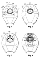
- Figure 1 shows a tank 101 of current motorcycle.
- the reservoir 101 comprises a plug 102.
- the plug 102 comprises at least one crown 103 of maintains and a movable portion 104 allowing the opening and closing of the plug 104.
- the ring 103 comprises, over its entire circumference, orifices for fixing the cap 102 to the tank 101. This fixing is carried out by means of bolts screwed into the reservoir through said orifices.
- the orifices are distributed on the ring of the cap symmetrically with respect to a longitudinal vertical plane 105 cutting the reservoir in two parts symmetrical to each other.
- the ring has 7 orifices 106 to 112.
- there are crowns having only 6 or 5 orifices, without this being detrimental to the implementation of the invention.
- FIG. 2 shows the tank 101 on which is fixed a device 201 according to the invention.
- This fixation is rigid in the sense that it is not elastic and made using screws. Once fixed, there is no play or slippage between the device according to the invention and the reservoir.
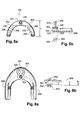
- FIG. 5a shows that the device 201 is a U-shaped piece, or a horseshoe, as it conforms to the ring 103 on the front part of the ring 103. The curvature of the piece 201 is does not exceed the semicircle.
- the piece 201 is also symmetrical with respect to the plane 105.
- the horseshoe structure thus makes it possible to define 2 lateral arms. Consider the left lateral arm 202, the right lateral arm 203 being symmetrical with respect to the plane 105.
- the arm 202 has at least one orifice 204 such that this orifice is in front of the orifice 108 when the part 201 is placed on the ring 103.
- An orifice 205 is then located opposite the orifice 110.
- the orifices 205, respectively 110, are symmetrical to the orifices 202, respectively 108, relative to the plane 105.
- the arm 202 also has 2 other orifices 206 and 208.
- the orifices 204, 206 and 208 are such that for a given model of tank cap there is always at least 1 opposite an orifice of the cap ring when the piece 201 is in place on said ring.
- the orifices of the part 201 are open.
- the piece 201 has a length
- the width of the arms is on average 1.5cm.
- the inner circumference of the part 201 conforms to the inner circumference of the ring 103.
- the orifice 204 is circular with a diameter substantially equal to 0.4 cm and located at a distance of substantially 3.3 cm from the base of the part 201, and at a distance substantially equal to 3 cm from the plane 105.
- the base of the piece 201 is a plane perpendicular to the plane 105 and tangential to the rear of the piece 201.
- the orifice 206 is substantially circular with a diameter substantially equal to 0.4 cm and located at a distance of substantially 2.6 cm from the base of the workpiece 201, and at a distance of substantially 3.5 cm from the plan 105.
- the orifice 208 is circular with a diameter substantially equal to 0.4 cm and located at a distance substantially equal to 1.2 cm from the base of the piece 201, and at a distance substantially equal to 4.2 cm from the plane 105.
- the centers of the orifices 204, 206 and 208 are aligned.
- the orifice 206 is oval along an axis passing through the centers of the orifices 204 and 208. According to this axis, the inside diameter of the orifice 206 is then substantially 0.8 cm.
- the orifices (204, 108) and (205, 110) which are used for the screwing of two bolts 202 and 203 serving to fix the part 201 and the crown 103 to the tank 101.
- These bolts are longer than the original ones used to fix the ring gear 103 to the tank 101. Indeed these bolts pass through the piece 201 and the crown 103.
- other orifices from 204 to 209 are used.
- the piece 201 is fixed via at least two orifices, one for each arm.
- FIG. 5a also shows that the part 201 comprises, intercepting the plane 105, a circular orifice 210.
- This orifice 210 is therefore located on the front part of the part 201, on either side of the plane 105 of symmetry.
- This orifice, with the upper part of the device according to the invention forms a docking interface for an accessory.
- FIG. 5b shows a side view of the part 201.
- FIG. 5b illustrates that the orifice 210 is the superposition of two cylinders, an upper cylinder 501 having an internal diameter substantially equal to 0.9 cm for a height substantially equal to 0.2 cm. And a lower cylinder 502, having the same axis as the cylinder 501.
- the cylinder 502 has an internal diameter substantially equal to 1.3 cm for a height of 0.9 cm.
- the first cylinder is formed by an outgrowth on the upper face of the part 201.
- the second cylinder is a recess of the part 201.
- FIG. 5b shows that the cylinder 502 comprises inside elastic means 503, plastic sleeve or spring, resting on the first cylinder 501.
- the inner diameter of the means 503 is therefore greater than or equal to the diameter of the first cylinder 501.
- the outer diameter of the means 503 is therefore less than or equal to the diameter of the second cylinder 502.
- the cylinder 502 comprises a circular plate 504 capable of compressing the means 503. Once the plate 504 is in place in the cylinder 502, it is closed by a ring 504 of greater or equal internal diameter or internal diameter of the cylinder 501.
- the crown 501 is attached to the workpiece 201 at the base of the cylinder 502.
- the tray 504 has an oval-shaped inner opening 505.
- Figure 5b also shows a resilient seal 506 located under the workpiece 201.
- This seal is placed between the motorcycle and the workpiece 201 when placing the workpiece 201 on the motorcycle.
- This seal protects the motorcycle and provides some elasticity to the motorcycle part 201, which has the effect of extending the life of the device according to the invention and the cap 102.
- the seal 506 has the same shape horseshoe the piece 201.
- the seal 506 has orifices identical to the orifices of the part 201.
- Figure 3 shows a first accessory, or part, 301 said first accessory being fixed on the reservoir 101.
- Figure 6a shows the part 301 seen from above.
- the piece 301 has a shape conforming to the piece 201, so a horseshoe shape such that once the piece 301 in position it does not interfere with the opening and closing of the tank cap 102.
- the piece 301 extends over a greater length than the piece 201.
- the piece 301 is symmetrical with respect to the plane 105.
- the piece 301 is also wider than the piece 201.
- the part 301 comprises, on its front part, an orifice 302, and in front of the orifice 302 and an orifice 303. These orifices are aligned on the plane 105.
- the orifice 302 has a diameter substantially equal to the upper diameter of the orifice 210.
- the orifice 302 is opening, that is to say that it passes through the part 301.
- the orifice 303 is located in front of the orifice 302 and has an internal diameter substantially equal to 2.1 cm.
- the upper part of the orifice 303 is conical.
- the orifice 303 is not open.
- the orifice 302 is opposite the orifice 210.
- FIG. 6b shows that, in a preferred variant of the invention, the part 301 comprises an axis 601 passing through said part at the orifice 302.
- the axis comprises, on its upper part, a head 602 whose diameter is greater to the diameter of the orifice 302.
- the axis 601 has on its lower part an ovate protuberance 603.
- the longitudinal extension of the protrusion 603 is such that it passes through the orifice 302, so too through the orifice 210.
- the protrusion 603 passes through the orifice 505.
- the axis 602 must be made a quarter turn so that the protrusion no longer passes through the orifice 505.
- This device thus makes it possible to fix together the first and second parts 201 and 301.
- the unlocking is done by making a new quarter turn to the axis 601.
- These quarter turns are made using a tool cooperating with the head 602.
- This tool is hexagonal key type.
- this is a special hexagon key with a special imprint, which ensures that only the person with the correct hexagon key can rotate the axis 601 quarter-turn. this is an anti-theft device.
- the axis device 601 is equivalent to a key device. It is therefore possible to use a traditional key lock in place of the axis 601.
- connection thus made between the parts 201 and 301 is elastic via the means 503. This allows a better transmission of forces and vibrations between the device 201 and part 301 and therefore between the motorcycle and the workpiece 301, which increases the reliability of the device according to the invention.
- Figures 3, 6a and 6b show that once the part 301 attached to the device 201, the part 301 completely covers the part 201, and in particular the holes 304 to 209. In this variant of the invention, once the piece 301 in place on the device 201, it is therefore no longer possible to access the nuts 202 and 203.
- the first, comprising the device 201 and accessory 301 is immovable. When the part 301 is fixed to the device 201.
- Figures 6a and 6b show that the part 301 comprises, at its upper surface, horizontal rails 605 and 606. These rails run along the part 301 symmetrically with respect to the plane 105.
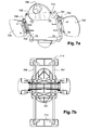
- Figure 7a shows the second accessory 701.
- the second accessory therefore comprises a substantially planar body 702.
- the accessory 701 is symmetrical with respect to the plane 105.
- FIG. 7a shows that the body 701 has on each of its side edges of the fins 703 and 704 attached to the body 702 via pins 705 and 706 horizontal and parallel to the plane 105.
- the fins 703 and 704 are rotatable about the axes 705 and 706 between a low position and a high position.
- the fins are constrained in the low position not springs or other elastic means. In the base position the fins are each in a horizontal plane.
- FIG. 7a shows that the second accessory comprises on its lower part before a cylindrical protuberance 706 of dimensions making it suitable for being introduced into the orifice 303.
- FIG. 4 shows the second accessory fixed to the first itself attached to the reservoir 101.
- the protrusion 706 is introduced into the orifice 303. This ensures both the correct positioning and holds it in place of the second accessory on the first.
- the fins 703 and 704 pinch the rails 605 and 606 against the body 702 to ensure the holding in place of the second accessory.
- the fins 703 and 704 form with the body 702 two clamps for gripping the part 301.
- Figure 7b shows the second accessory 701 seen from above.
- the second accessory 701 comprises two longitudinal rails 707 and 708 sliding in channels 709 and 710 of the upper part of the body 702.
- the rails 708 are of the same length, parallel is connected at each of their ends by rigid plates 711 and 712. It is on these trays that are fixed the accessory or accessories that it is desired to attach to the motorcycle via the device according to the invention.
- the position of the rails 707 and 708 is therefore variable longitudinally. Once the correct position is found, the rails are held in place by at least one plate screwed to the body 702 and now the rails 707 and 708 in place by pressing against the bottom of the channels 709 and 710.
- the body 702 comprises two plates, one at the front, the other at the back, to press the rails at the bottom of the channels.
- the good position of rails is determined by the size of the accessory, the size of the driver and model of the bike. In practice the accessories are either panniers or GPS devices. The adjustment of the position of the rails is usually done only once.
- Figure 8 is a side view of the tank 101 on which is fixed a bag 801 via a device according to the invention.
- Figure 8 shows the fin 703 located under the bag 801 and above the tank 101, easily accessible even with gloves.
- the device according to the invention can be used directly for securing to the second accessory. It suffices for this purpose that the docking interface of the device according to the invention is compatible with the docking interface of the second accessory.
- Such an example consists in producing the piece 201 and the piece 301 in one piece through which the orifices 204 to 209.
- many forms of docking interfaces can be envisaged for the device according to the invention. In these cases the orifice 210 becomes optional and the fixing bolts of the device according to the invention remain accessible.
- the orifices of the device according to the invention can be fused until they only form 2 or 1 apertures per branch of the U.
- a very rigid material must be provided for the device according to the invention.
- it is made of aluminum. In other implementation it is made of another metal or a rigid plastic.
Landscapes
- Engineering & Computer Science (AREA)
- Mechanical Engineering (AREA)
- Purses, Travelling Bags, Baskets, Or Suitcases (AREA)
- Fittings On The Vehicle Exterior For Carrying Loads, And Devices For Holding Or Mounting Articles (AREA)
- Motorcycle And Bicycle Frame (AREA)
- Automatic Cycles, And Cycles In General (AREA)
- Professional, Industrial, Or Sporting Protective Garments (AREA)
Applications Claiming Priority (1)
| Application Number | Priority Date | Filing Date | Title |
|---|---|---|---|
| FR0452460A FR2876977B1 (fr) | 2004-10-27 | 2004-10-27 | Dispositif universel d'arrimage d'au moins un accessoire a une motocyclette |
Publications (2)
| Publication Number | Publication Date |
|---|---|
| EP1652761A2 true EP1652761A2 (de) | 2006-05-03 |
| EP1652761A3 EP1652761A3 (de) | 2008-12-03 |
Family
ID=34950262
Family Applications (1)
| Application Number | Title | Priority Date | Filing Date |
|---|---|---|---|
| EP05300868A Withdrawn EP1652761A3 (de) | 2004-10-27 | 2005-10-26 | Befestigungseinrichtung für Fahrradzubehör |
Country Status (2)
| Country | Link |
|---|---|
| EP (1) | EP1652761A3 (de) |
| FR (1) | FR2876977B1 (de) |
Cited By (10)
| Publication number | Priority date | Publication date | Assignee | Title |
|---|---|---|---|---|
| EP2371687A1 (de) * | 2010-03-26 | 2011-10-05 | Honda Access Corporation | Elektrozubehörmontagevorrichtung für Motorräder |
| EP2371686A1 (de) * | 2010-03-29 | 2011-10-05 | Honda Access Corporation | Elektrozubehörmontagevorrichtung für Motorräder |
| DE102010037912A1 (de) * | 2010-10-01 | 2012-04-05 | Fidlock Gmbh | Vorrichtung zum Befestigen eines Gepäckstückes oder Motorradzubehörs auf dem Tank eines Motorrades |
| JP2012183894A (ja) * | 2011-03-04 | 2012-09-27 | Honda Motor Co Ltd | 鞍乗り型車両 |
| FR2980158A1 (fr) * | 2011-09-20 | 2013-03-22 | Iscd Sarl | Kit de support de tiers element sur reservoir de motocyclette |
| ES2395450R1 (es) * | 2011-04-27 | 2013-10-08 | Jimenez Jose Antonio Cubeles | Maleta para motocicletas |
| US10207761B2 (en) | 2016-05-24 | 2019-02-19 | Harley-Davidson Motor Company Group, LLC | Fuel tank assembly, motorcycle accessory, and method of attachment |
| EP3819198A1 (de) * | 2019-11-05 | 2021-05-12 | SW-Motech GmbH & Co. KG | Adapter zum anbringen von gegenstaenden am tank eines motorrades |
| CN114401866A (zh) * | 2019-07-22 | 2022-04-26 | 庞巴迪动力产品公司 | 用于将存储容器附接到车辆的附接系统 |
| WO2024188574A1 (de) * | 2023-03-10 | 2024-09-19 | Bayerische Motoren Werke Aktiengesellschaft | Tank für ein kraftrad sowie kraftrad |
Family Cites Families (4)
| Publication number | Priority date | Publication date | Assignee | Title |
|---|---|---|---|---|
| ITMI20022179A1 (it) * | 2002-10-15 | 2004-04-16 | Stefano Ognissanti | Il manopoliero |
| JP4190273B2 (ja) * | 2002-12-09 | 2008-12-03 | タナックス株式会社 | オートバイ用支持具およびバッグ |
| IT1347789B1 (it) * | 2003-02-25 | 2008-10-02 | Stefano Ognissanti | Sistema di supporto universale per accessori di motocicli |
| DE20314313U1 (de) * | 2003-09-15 | 2003-11-20 | Elsner, Guido, 45475 Mülheim | Halter zur Befestigung an einem Kraftrad |
-
2004
- 2004-10-27 FR FR0452460A patent/FR2876977B1/fr not_active Expired - Fee Related
-
2005
- 2005-10-26 EP EP05300868A patent/EP1652761A3/de not_active Withdrawn
Non-Patent Citations (1)
| Title |
|---|
| None |
Cited By (13)
| Publication number | Priority date | Publication date | Assignee | Title |
|---|---|---|---|---|
| EP2371687A1 (de) * | 2010-03-26 | 2011-10-05 | Honda Access Corporation | Elektrozubehörmontagevorrichtung für Motorräder |
| EP2371686A1 (de) * | 2010-03-29 | 2011-10-05 | Honda Access Corporation | Elektrozubehörmontagevorrichtung für Motorräder |
| JP2011207312A (ja) * | 2010-03-29 | 2011-10-20 | Honda Motor Co Ltd | 鞍乗型車両の装備品取付装置 |
| DE102010037912A1 (de) * | 2010-10-01 | 2012-04-05 | Fidlock Gmbh | Vorrichtung zum Befestigen eines Gepäckstückes oder Motorradzubehörs auf dem Tank eines Motorrades |
| DE102010037912B4 (de) * | 2010-10-01 | 2021-02-25 | Fidlock Gmbh | Vorrichtung zum Befestigen eines Gepäckstückes oder Motorradzubehörs auf dem Tank eines Motorrades |
| JP2012183894A (ja) * | 2011-03-04 | 2012-09-27 | Honda Motor Co Ltd | 鞍乗り型車両 |
| ES2395450R1 (es) * | 2011-04-27 | 2013-10-08 | Jimenez Jose Antonio Cubeles | Maleta para motocicletas |
| FR2980158A1 (fr) * | 2011-09-20 | 2013-03-22 | Iscd Sarl | Kit de support de tiers element sur reservoir de motocyclette |
| US10207761B2 (en) | 2016-05-24 | 2019-02-19 | Harley-Davidson Motor Company Group, LLC | Fuel tank assembly, motorcycle accessory, and method of attachment |
| CN114401866A (zh) * | 2019-07-22 | 2022-04-26 | 庞巴迪动力产品公司 | 用于将存储容器附接到车辆的附接系统 |
| US12172727B2 (en) | 2019-07-22 | 2024-12-24 | Bombardier Recreational Products Inc. | Attachment system for attaching a storage container to a vehicle |
| EP3819198A1 (de) * | 2019-11-05 | 2021-05-12 | SW-Motech GmbH & Co. KG | Adapter zum anbringen von gegenstaenden am tank eines motorrades |
| WO2024188574A1 (de) * | 2023-03-10 | 2024-09-19 | Bayerische Motoren Werke Aktiengesellschaft | Tank für ein kraftrad sowie kraftrad |
Also Published As
| Publication number | Publication date |
|---|---|
| FR2876977B1 (fr) | 2008-04-18 |
| FR2876977A1 (fr) | 2006-04-28 |
| EP1652761A3 (de) | 2008-12-03 |
Similar Documents
| Publication | Publication Date | Title |
|---|---|---|
| EP2531393B1 (de) | Ausziehbares zweirädriges fahrzeug | |
| EP0669225B1 (de) | Fahrradhalter und dessen Fahrrad-Befestigungseinrichtung | |
| EP0141757A1 (de) | Fahrradträger zur Befestigung auf Trägerbrücken von Kraftfahrzeugen | |
| EP3187402B1 (de) | Sattelträger einer scheibenbremse für ein fahrrad oder ähnlich | |
| EP1652761A2 (de) | Befestigungseinrichtung für Fahrradzubehör | |
| EP3187406A1 (de) | Lasche eines hinteren arms eines fahrrads oder ähnlichem, und fahrrad, das eine solche lasche eines hinteren arms umfasst | |
| FR3018260A1 (fr) | Ensemble d'elements permettant de constituer une trottinette pour enfants | |
| EP1801004B1 (de) | Klapprad | |
| EP1076003B1 (de) | Vorrichtung zur Befestigung eines Gegenstandes, insbesondere einer Tasche, auf einem Motorradtank | |
| EP1652762A2 (de) | Befestigungseinrichtung für Fahrradzubehör | |
| FR3027279A1 (fr) | Dispositif telescopique et application a un velo, en particulier un velo pliant | |
| FR2666775A1 (fr) | Dispositif de fixation d'un cycle pourvu d'une selle sur un support equipant un vehicule automobile. | |
| FR3117992A1 (fr) | Accessoire de support pour vélocipède | |
| FR3101604A1 (fr) | Trottinette pliable | |
| FR2965244A1 (fr) | Remorque pour vehicule deux-roues avec systeme d'attelage particulier | |
| EP1457411A1 (de) | Fahrradständer mit Schwerpunktsattelhalterung | |
| EP0814014A1 (de) | Diebstahlsicherung für Fahrrad | |
| EP1803634A1 (de) | Zusammenklappbares Fahrrad mit einem am Tretkurbelkasten positionierten Gelenk | |
| FR3113013A1 (fr) | Porte-vélo | |
| FR3156088A1 (fr) | Système de maintien d’un vélo en position verticale | |
| FR3132455A1 (fr) | Espaceur de protection des commandes fixées au guidon | |
| FR2509249A1 (fr) | Pedale de bicyclette permettant l'accrochage d'une chaussure en position prereglee | |
| FR3101605A1 (fr) | Trottinette pliable | |
| EP1227033A1 (de) | Einrichtung zum Verwandeln von Einzelfahrrädern in ein Tandemfahrrad | |
| FR3119156A1 (fr) | Porte-bagage multifonctions pour cycle |
Legal Events
| Date | Code | Title | Description |
|---|---|---|---|
| PUAI | Public reference made under article 153(3) epc to a published international application that has entered the european phase |
Free format text: ORIGINAL CODE: 0009012 |
|
| AK | Designated contracting states |
Kind code of ref document: A2 Designated state(s): AT BE BG CH CY CZ DE DK EE ES FI FR GB GR HU IE IS IT LI LT LU LV MC NL PL PT RO SE SI SK TR |
|
| AX | Request for extension of the european patent |
Extension state: AL BA HR MK YU |
|
| RIN1 | Information on inventor provided before grant (corrected) |
Inventor name: BOUCHENY, FREDERIC Inventor name: PIERON, ISABELLE Inventor name: DE ROALDES, OLIVIER |
|
| PUAL | Search report despatched |
Free format text: ORIGINAL CODE: 0009013 |
|
| RIC1 | Information provided on ipc code assigned before grant |
Ipc: B62J 9/00 20060101ALI20081022BHEP Ipc: B62J 7/08 20060101ALI20081022BHEP Ipc: B62J 35/00 20060101ALI20081022BHEP Ipc: B62J 11/00 20060101AFI20081022BHEP |
|
| AK | Designated contracting states |
Kind code of ref document: A3 Designated state(s): AT BE BG CH CY CZ DE DK EE ES FI FR GB GR HU IE IS IT LI LT LU LV MC NL PL PT RO SE SI SK TR |
|
| AX | Request for extension of the european patent |
Extension state: AL BA HR MK YU |
|
| AKX | Designation fees paid | ||
| REG | Reference to a national code |
Ref country code: DE Ref legal event code: 8566 |
|
| STAA | Information on the status of an ep patent application or granted ep patent |
Free format text: STATUS: THE APPLICATION IS DEEMED TO BE WITHDRAWN |
|
| 18D | Application deemed to be withdrawn |
Effective date: 20090604 |