EP1652802A2 - Dispositif pour le changement automatique de piles - Google Patents
Dispositif pour le changement automatique de piles Download PDFInfo
- Publication number
- EP1652802A2 EP1652802A2 EP05022188A EP05022188A EP1652802A2 EP 1652802 A2 EP1652802 A2 EP 1652802A2 EP 05022188 A EP05022188 A EP 05022188A EP 05022188 A EP05022188 A EP 05022188A EP 1652802 A2 EP1652802 A2 EP 1652802A2
- Authority
- EP
- European Patent Office
- Prior art keywords
- elements
- leaf springs
- stack
- storage elements
- auxiliary
- Prior art date
- Legal status (The legal status is an assumption and is not a legal conclusion. Google has not performed a legal analysis and makes no representation as to the accuracy of the status listed.)
- Withdrawn
Links
- 239000000463 material Substances 0.000 claims abstract description 9
- 238000012545 processing Methods 0.000 claims description 14
- 238000005452 bending Methods 0.000 claims description 9
- 230000008859 change Effects 0.000 claims description 7
- 230000001360 synchronised effect Effects 0.000 claims description 5
- 230000009471 action Effects 0.000 claims description 4
- 230000000284 resting effect Effects 0.000 claims description 4
- 238000005461 lubrication Methods 0.000 claims description 2
- 239000012528 membrane Substances 0.000 claims description 2
- 239000002184 metal Substances 0.000 claims description 2
- 230000009467 reduction Effects 0.000 claims description 2
- 238000000151 deposition Methods 0.000 claims 2
- 230000000694 effects Effects 0.000 claims 1
- 239000012530 fluid Substances 0.000 claims 1
- 230000002265 prevention Effects 0.000 claims 1
- 230000002829 reductive effect Effects 0.000 description 4
- 238000003780 insertion Methods 0.000 description 3
- 230000037431 insertion Effects 0.000 description 3
- 239000000758 substrate Substances 0.000 description 3
- 238000013461 design Methods 0.000 description 2
- 238000000605 extraction Methods 0.000 description 2
- 238000005096 rolling process Methods 0.000 description 2
- 230000003068 static effect Effects 0.000 description 2
- 230000006978 adaptation Effects 0.000 description 1
- 238000010276 construction Methods 0.000 description 1
- 239000004744 fabric Substances 0.000 description 1
- 230000002401 inhibitory effect Effects 0.000 description 1
- 238000012423 maintenance Methods 0.000 description 1
- 238000000034 method Methods 0.000 description 1
- 230000008569 process Effects 0.000 description 1
- 239000002699 waste material Substances 0.000 description 1
Images



Classifications
-
- B—PERFORMING OPERATIONS; TRANSPORTING
- B65—CONVEYING; PACKING; STORING; HANDLING THIN OR FILAMENTARY MATERIAL
- B65H—HANDLING THIN OR FILAMENTARY MATERIAL, e.g. SHEETS, WEBS, CABLES
- B65H1/00—Supports or magazines for piles from which articles are to be separated
- B65H1/26—Supports or magazines for piles from which articles are to be separated with auxiliary supports to facilitate introduction or renewal of the pile
-
- B—PERFORMING OPERATIONS; TRANSPORTING
- B65—CONVEYING; PACKING; STORING; HANDLING THIN OR FILAMENTARY MATERIAL
- B65H—HANDLING THIN OR FILAMENTARY MATERIAL, e.g. SHEETS, WEBS, CABLES
- B65H2220/00—Function indicators
- B65H2220/09—Function indicators indicating that several of an entity are present
-
- B—PERFORMING OPERATIONS; TRANSPORTING
- B65—CONVEYING; PACKING; STORING; HANDLING THIN OR FILAMENTARY MATERIAL
- B65H—HANDLING THIN OR FILAMENTARY MATERIAL, e.g. SHEETS, WEBS, CABLES
- B65H2402/00—Constructional details of the handling apparatus
- B65H2402/50—Machine elements
- B65H2402/54—Springs, e.g. helical or leaf springs
-
- B—PERFORMING OPERATIONS; TRANSPORTING
- B65—CONVEYING; PACKING; STORING; HANDLING THIN OR FILAMENTARY MATERIAL
- B65H—HANDLING THIN OR FILAMENTARY MATERIAL, e.g. SHEETS, WEBS, CABLES
- B65H2405/00—Parts for holding the handled material
- B65H2405/30—Other features of supports for sheets
- B65H2405/32—Supports for sheets partially insertable - extractable, e.g. upon sliding movement, drawer
- B65H2405/323—Cantilever finger member, e.g. reciprocating in parallel to plane of handled material
-
- B—PERFORMING OPERATIONS; TRANSPORTING
- B65—CONVEYING; PACKING; STORING; HANDLING THIN OR FILAMENTARY MATERIAL
- B65H—HANDLING THIN OR FILAMENTARY MATERIAL, e.g. SHEETS, WEBS, CABLES
- B65H2515/00—Physical entities not provided for in groups B65H2511/00 or B65H2513/00
- B65H2515/81—Rigidity; Stiffness; Elasticity
Definitions
- the invention relates to a device for an automatic non-stop stack change in a sheet-processing machine according to the preamble of patent claim 1.
- Affected by the invention are areal substrates processing machines, in particular sheet-fed presses, with at least one processing station in the form of a printing unit, a processing station feeding sheet feeder, and the processed sheet grading stacking boom and an auxiliary pile carrier, in a direction of extension from a standby position in a Working position and vice versa is adjustable and constructed in terms of their flexural stiffness advantageously convertible storage elements.
- DE 42 15 791 C2 discloses a stacking table with a device for renewing or removing a stack during the continuous operation of a sheet-processing machine.
- As storage elements chains are provided, which are supportable after resting on the support elements in the direction of the weight of the stack ie rigid.
- the outer U-shaped chain links are supported with their web on the top of the inner chain links.
- a link chain-like design of the storage elements is described.
- the so-called rolling rods consist of successively arranged, extending over the bearing pin against each other supporting inner Stabgliedem and an outer rod member and an outer rod member engaging, the inner rod members and the bearing pin connecting tensioning cable.
- DE 102 33 786 A1 describes a two-dimensional substrate-processing machine with an auxiliary stack carrier.
- the storage elements are formed of articulated rods, whose so-called support members engages a respectively opposite to the insertion direction extending extension in the insertion direction pointing towards the extension of the übemambasten in the insertion direction trailing support member.
- a disadvantage of these devices is that the hinge chain-like arrangement of the support members tends to mark on the substrate. Due to poor flatness and / or ripple of the auxiliary pile bottom and the top of the new stack can cause damage to the overlying sheet by the movement joints of the support members in the return of the hinged only in one direction storage elements. Due to the principle caused by the slight tilting between support elements and auxiliary stack on the one hand and the new stack on the other hand to high tensile forces. Furthermore, a large number of very precisely manufactured individual parts are required to realize a plurality of such storage elements. The pivot pins and the holes in the individual support members are subject to normal wear during operation. An increase in joint play quickly manifests itself in an increase in the maximum deflection under load.
- the object of the invention is therefore to avoid the disadvantages of the known devices in a device according to the preamble of patent claim 1.
- the storage elements can be pushed by a double-sided flexibility on the one hand from a space-saving standby position by a grooved non-stop pallet in the working position and on the other hand in the return from the working position between the two stacks with the lowest possible Traction can be moved.
- a tilting of the storage elements between the two sheet stacks is minimized in principle here.
- the multilayer stacked leaf springs built-up storage elements by the positive or non-positive sub binding of relative movements between the leaf springs in the longitudinal direction for receiving the initiated by the residual stack weight proportionate line load stiffening reaching stiffened. Due to the continuous, uninterrupted contact surfaces of these flexible storage elements, the markings can be minimized.
- a further advantageous embodiment consists in the arrangement of a pressurized, expandable in height element between the respective outer leaf springs of the flexible storage element.
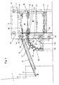
- FIG. 1 shows the area of a sheet feeder 5 with an arrangement according to the invention of an auxiliary piling device 22 with flexible storage elements 23.
- a first processing station of a sheet processing machine 1 is arranged below, which is connected to the sheet feeder 5 for supplying a sheet flow 18 through a suction belt table 17.
- the sheet feeder 5 is shown in the state in which a residual or auxiliary stack 19 is still supported by a standby position B lying outside the stack area of the sheet feeder 5 in a working position A within the stack area.
- a new stack or stack 20 is already up a pile support plate 7 positioned and brought directly under the storage elements 23 of the auxiliary stacking device 22.
- a respective overhead printing material sheet of the auxiliary stack 19 is sucked by a suction head 6 arranged above it at its trailing edge and separated from the underlying sheet to subsequently pushed in sheet travel direction L over a folded back sheet flap 13 and between clock rollers 14 and a conveyor roller 15.
- the acquired sheet is then further conveyed by conveyor belts of a belt table, which is designed here as Saugb Stisch 17, while the suction head 6 already singles and brings the next sheet.
- a subfloor sheet stream 18 produced in this way is fed on the suction belt table 17 to a delivery table 2 of the sheet processing machine 1.
- each sheet is applied to deck marks 3 and 4 front marks, and laterally aligned by means of a sozieh coupled, not shown, and then retracted into the first processing station.
- the maintenance of a constant height position of the stack top edge of the auxiliary stack 19 or of the main stack 20 is a necessary prerequisite.
- the altitude of the stack top edge is detected with a corresponding sensor and kept constant by the tracking of the auxiliary stacking device 22.
- the main stack 20 which has been moved from below, as shown, is combined with the auxiliary stack 19. This is done with synchronous stroke of auxiliary and main stacks 19 and 20 by pulling out the storage elements 23 of the auxiliary stacking device 3 in sheet travel direction L in the ready position B.
- an outer and an inner circular arc guide 29 and 30 are used with sliding or rolling elements.
- the storage elements 23 are attached individually or in groups to one or more pivoting traverses 25. The arcuate movement is initiated by one or more pivot arms 24, which are supported by one or more drive shafts 26 are turned.
- the standby position B and the working position A are also indicated with respect to the swing arms 24.
- the auxiliary stacking device 22 and the front and rear auxiliary stacking traverse 8 and 9 is moved to its lowest position and held there.
- the front Hilfsstapeltraverse 8 forms expediently with the carriage 27 of the auxiliary stacking device a unit.
- a new batch change process can begin.
- the stroke of the auxiliary stacking device 22 is activated and synchronized with the stroke of the main stack 20 so that the storage element tips 38 in FIG the grooves of the non-stop pallet 21 can be retracted.
- the storage elements 23 are stiffened so that they can take over the load of the auxiliary stack 19. For example, if the storage elements 23 consist of a multi-layered arrangement of leaf springs, they can be stiffened by inhibiting the relative longitudinal movements between the leaf springs.
- the storage elements 23 of the auxiliary stacking device 22 Once the main stack has reached the storage elements 23 of the auxiliary stacking device 22 and has taken over the load of the auxiliary stack 19, the storage elements 23, which are designed to be variable in rigidity, be unlocked and so flexible upwards and downwards elastically deformable. As a result, low forces for extracting the storage elements 23 can be achieved even when processing wavy printing material stacks.
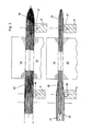
- FIG. 2 shows a first embodiment of an inventive embodiment of a multi-layered storage element 32.
- the storage element 32 by way of example consists of twelve individual leaf springs made of a material with a high yield strength and still the greatest possible elastic deformability.
- the leaf springs are shown here as packages of upper leaf springs 33, middle leaf springs 34 and lower leaf springs 35.
- the arrangement of individual leaf springs makes it possible for each individual leaf spring to be elastically deformed along a radius of curvature R. In its working position A, however, the locked storage element 32 is able to receive a respective proportion of the load of the auxiliary stack 19.
- the stiffening of the storage element 32 in the form of the multilayer bending beam shown is effected by a positive and / or non-positive locking of the relative longitudinal movement between the individual leaf springs.
- This locking can be done according to the invention either in the area of the front and / or rear auxiliary stack traverse 8 and 9 respectively.
- locking elements 39 and 40 can be used.
- the locking elements 39, 40 may be formed as cylindrical or conical pins, which may be rigid or radially expandable within corresponding bores 36, 37.
- the multilayer storage element 32 is compressed by the surface pressure resulting from the proportionate auxiliary pile weight on the uppermost leaf spring. As a result, an undesired Ausknickterrorism the storage element 32 is counteracted.
- FIG. 3 there is shown another embodiment of a multi-layered tray member 32 formed by withdrawing a few internal leaf springs, e.g. the package of the middle leaf springs 34, in height is reducible.
- the distance between the stacks 19 and 20 can be reduced in this way in order to minimize the drop in the stack top edge of the auxiliary stack 19 when pulling the storage elements 32 completely.
- the rigidity of the remaining remaining flexible storage element 32 is also reduced.
- the extraction of the thus modified storage elements 32 is additionally facilitated, since an optimal adaptation to possibly uneven stacking surfaces between the auxiliary stack 19 and main stack 20 is possible.
- FIG. 4 shows a special embodiment of a multilayer storage element 32.
- a respective overlapping arrangement of oblong holes 41 in the region of the package of the central leaf springs 34 is provided.
- a compressed air stream 43 can be passed through the storage element 32.
- the compressed air flow 43 acts on outlet bores 42, which are arranged in the upper and the lower leaf springs 33 and 35, respectively. Due to the compressed air emerging from the outlet bores 42, the two friction pairings between the printing substrate surfaces on the underside of the auxiliary stack 19 or at the top of the main stack 20 and the flexible storage element 32 are actively “lubricated” pneumatically. Thus, the static friction is reduced at the friction points and it can be a mark-free extraction of the storage elements 32 between the auxiliary stack 19 and the main stack 20 guaranteed.
- a fluidically adjustable preferably in height diaphragm actuator 44 is arranged.
- the actuator 44 is in its lowest height so as not to hinder the passage of the groove of the non-stop pallet 21.
- the diaphragm actuator 44 is then in a depressurized starting position.
- the fluidic membrane actuator 44 can be pressurized and thus expanded in height.
- the hip stack 19 is lifted from the thus increased storage elements 32 steadily from the pallet surface.
- a particularly high bending stiffness of storage elements 32 of the type already described is achieved.
- an outer circular arc guide 29, an inner circular arc guide 30 and a pressure roller 31 is arranged, by means of which the leaf springs 33, 34, 35 existing storage element 32 can be deflected before being fed into the stack area in a horizontal direction of action.
- the leaf springs 33, 34, 35 existing storage element 32 can be deflected before being fed into the stack area in a horizontal direction of action.
- the device is arranged such that a deflection at a deflection angle of approximately 45 degrees and a second deflection guide 46 take place at a further deflection angle of 45 degrees relative to the first deflection guide 45 by means of a first deflection guide 45.
- the deflection guides 45, 46 By means of the deflection guides 45, 46, the direction of action of the storage element 32 with respect to the planar extension of the leaf springs 33, 34, 35 is rotated by a total of 90 degrees. This results in a much higher bending stiffness in relation on the load direction by a male residual stack in the sheet feeder.
- FIG. 7 shows a detail of the device according to FIG.
- the tray member 32 is associated with a strip-shaped lower cover 47 and a strip-shaped upper cover 48.
- the covers 47, 48 are made of flexible strips of metal or plastic, which have at least the width of the height of the storage element 32.
- the covers 47, 48 are supplied in synchronous movement with the storage element 32, so that they rest against the now upwardly or downwardly directed side edges of the leaf springs 33, 34, 35.
- the supply or discharge of the covers 47, 48 to / from the stacking area can be carried out by a roll or another type of storage device with suitable feed elements.
- covers 47, 48 By means of the covers 47, 48, all leaf springs 33, 34, 35 can be completely covered at their side edges, which - as described - in this case are directed upwards or downwards on the storage element 32. In this way, the covers 47, 48 serve to protect the parts of the printing material coming into contact with the storage element 32 during a stack change from damage. In addition, with a selection of suitable materials of the covers 47, 48 an improved sliding action of the storage element 32 is achieved with respect to the adjacent printing material.
- the guide brackets 49, 50 are inserted in the same manner as the covers 47, 48 by bringing it to the side edges of the leaf springs 33, 34, 35.
- the guide brackets 49, 50 here have angled edges, which engage around the outer edges of the leaf springs 33 and 35 when it rests on the storage element 32. With that the leaf springs 33, 34, 35 combined into a package. A lateral buckling of the storage element 32 or from external leaf springs 33 and 35 as a result of the load of the resting printing material is therefore reliably prevented.
Landscapes
- Engineering & Computer Science (AREA)
- Mechanical Engineering (AREA)
- Supply, Installation And Extraction Of Printed Sheets Or Plates (AREA)
- Sheets, Magazines, And Separation Thereof (AREA)
- Pile Receivers (AREA)
- Separation, Sorting, Adjustment, Or Bending Of Sheets To Be Conveyed (AREA)
Applications Claiming Priority (2)
| Application Number | Priority Date | Filing Date | Title |
|---|---|---|---|
| DE200410052314 DE102004052314A1 (de) | 2004-10-28 | 2004-10-28 | Vorrichtung für einen automatischen Stapelwechsel |
| DE102005004940 | 2005-02-04 |
Publications (2)
| Publication Number | Publication Date |
|---|---|
| EP1652802A2 true EP1652802A2 (fr) | 2006-05-03 |
| EP1652802A3 EP1652802A3 (fr) | 2007-12-05 |
Family
ID=35708678
Family Applications (1)
| Application Number | Title | Priority Date | Filing Date |
|---|---|---|---|
| EP05022188A Withdrawn EP1652802A3 (fr) | 2004-10-28 | 2005-10-12 | Dispositif pour le changement automatique de piles |
Country Status (2)
| Country | Link |
|---|---|
| EP (1) | EP1652802A3 (fr) |
| JP (1) | JP3884051B2 (fr) |
Citations (4)
| Publication number | Priority date | Publication date | Assignee | Title |
|---|---|---|---|---|
| DE4215791C2 (de) | 1992-05-13 | 1999-10-21 | Heidelberger Druckmasch Ag | Stapeltisch mit einer Einrichtung zum Erneuern oder Abnehmen eines Stapels während des fortlaufenden Betriebes einer bogenverarbeitenden Maschine |
| DE4424287C2 (de) | 1994-07-09 | 2001-05-31 | Koenig & Bauer Ag | Hilfsstapeleinrichtung |
| EP1340705A2 (fr) | 2002-02-27 | 2003-09-03 | E.C.H. WILL GmbH | Dispositif pour former et enlever des piles de feuilles, avec une bande séparatrice |
| DE10233786A1 (de) | 2002-07-25 | 2004-02-05 | Heidelberger Druckmaschinen Ag | Flächige Bedruckstoffe verarbeitende Maschine mit einem Hilfsstapelträger |
-
2005
- 2005-10-12 EP EP05022188A patent/EP1652802A3/fr not_active Withdrawn
- 2005-10-21 JP JP2005307437A patent/JP3884051B2/ja not_active Expired - Fee Related
Patent Citations (4)
| Publication number | Priority date | Publication date | Assignee | Title |
|---|---|---|---|---|
| DE4215791C2 (de) | 1992-05-13 | 1999-10-21 | Heidelberger Druckmasch Ag | Stapeltisch mit einer Einrichtung zum Erneuern oder Abnehmen eines Stapels während des fortlaufenden Betriebes einer bogenverarbeitenden Maschine |
| DE4424287C2 (de) | 1994-07-09 | 2001-05-31 | Koenig & Bauer Ag | Hilfsstapeleinrichtung |
| EP1340705A2 (fr) | 2002-02-27 | 2003-09-03 | E.C.H. WILL GmbH | Dispositif pour former et enlever des piles de feuilles, avec une bande séparatrice |
| DE10233786A1 (de) | 2002-07-25 | 2004-02-05 | Heidelberger Druckmaschinen Ag | Flächige Bedruckstoffe verarbeitende Maschine mit einem Hilfsstapelträger |
Also Published As
| Publication number | Publication date |
|---|---|
| JP2006124177A (ja) | 2006-05-18 |
| EP1652802A3 (fr) | 2007-12-05 |
| JP3884051B2 (ja) | 2007-02-21 |
Similar Documents
| Publication | Publication Date | Title |
|---|---|---|
| EP3736235B1 (fr) | Dispositif de manipulation de pile de produits pliés, plieuse correspondante, et procédé de transfert de piles de produits | |
| DE3937995C2 (de) | Verfahren und Vorrichtung zur Bogenriesvereinzelung und zur Riesablage | |
| DE3743805C1 (de) | Trennsaugereinrichtung fuer einen Anleger einer Druckmaschine | |
| DE4211353C2 (de) | Hilfsstapelträger für eine Bogenstapelhubvorrichtung | |
| EP0773179B1 (fr) | Dispositif pour faire des piles auxiliaires pendant l'échange en continue de piles dans un empileur d'une machine à imprimer | |
| EP0798252A2 (fr) | Dispositif de changement automatique du format dans le dispositif de décharge d'une machine à imprimer rotative | |
| DE102022118979A1 (de) | Auslage und Verfahren zum Betreiben einer Auslage mit einem von einem Stapelhubantrieb vertikal verlagerbaren Stapelträger | |
| DE102022118978A1 (de) | Auslage und Verfahren zum Betreiben einer Auslage mit einem von einem Stapelhubantrieb vertikal verlagerbaren Stapelträger | |
| DE102004052314A1 (de) | Vorrichtung für einen automatischen Stapelwechsel | |
| EP1384695B1 (fr) | Machine de traitement de feuilles avec un dispositif d'empilage auxiliaire | |
| EP1652802A2 (fr) | Dispositif pour le changement automatique de piles | |
| EP2141101B1 (fr) | Dispositif d'aspiration de tableau en tôle et dispositif de transport de tableaux en tôle dans une machine d'impression de tôle ou une machine de laquage de tôle | |
| DE4129136A1 (de) | Einrichtung zum richten eines bogenstapels | |
| DE102006018769B3 (de) | Vorrichtung zum Transport bogenförmiger flacher Gegenstände | |
| DE19844231C1 (de) | Vorrichtung zum Ablegen von Blättern eines Aufzeichnungsträgers | |
| DE19911524C2 (de) | Vorrichtung zum Wechseln von Bogenstapeln in einem Ausleger einer Bogendruckmaschine | |
| DE2502790C2 (de) | Rundstapelbogenanleger | |
| DE19933064B4 (de) | Einrichtung zum Anlegen von Bogen | |
| DE10249034C1 (de) | Zwischenstapeleinrichtung im Ausleger einer bogenverarbeitenden Maschine, insbesondere Druckmaschine | |
| DE19649319C2 (de) | Vorrichtung zur Handhabung von aus Bogen gebildeten Stapeln | |
| DE19937486B4 (de) | Transportfahrzeug zur Entnahme eines Warenbaums aus einer Webmaschine, Schneidvorrichtung für das Transportfahrzeug zum Abtrennen einer Warenbahn und Verfahren zur Entnahme des Warenbaums aus der Webmaschine | |
| DE4013082A1 (de) | Schuppenstromanleger | |
| DE102009046987B4 (de) | Auslage einer bogenverarbeitenden Maschine mit einem Bogen aufnehmenden Auslagestapel und ein Verfahren zum Stapelwechsel | |
| AT501791A2 (de) | Bogenhinterkantenstütze | |
| EP1010655B1 (fr) | Dispositif d'enroulement d'une bande |
Legal Events
| Date | Code | Title | Description |
|---|---|---|---|
| PUAI | Public reference made under article 153(3) epc to a published international application that has entered the european phase |
Free format text: ORIGINAL CODE: 0009012 |
|
| AK | Designated contracting states |
Kind code of ref document: A2 Designated state(s): AT BE BG CH CY CZ DE DK EE ES FI FR GB GR HU IE IS IT LI LT LU LV MC NL PL PT RO SE SI SK TR |
|
| AX | Request for extension of the european patent |
Extension state: AL BA HR MK YU |
|
| PUAL | Search report despatched |
Free format text: ORIGINAL CODE: 0009013 |
|
| AK | Designated contracting states |
Kind code of ref document: A3 Designated state(s): AT BE BG CH CY CZ DE DK EE ES FI FR GB GR HU IE IS IT LI LT LU LV MC NL PL PT RO SE SI SK TR |
|
| AX | Request for extension of the european patent |
Extension state: AL BA HR MK YU |
|
| 17P | Request for examination filed |
Effective date: 20080605 |
|
| RAP1 | Party data changed (applicant data changed or rights of an application transferred) |
Owner name: MANROLAND AG |
|
| 17Q | First examination report despatched |
Effective date: 20080704 |
|
| AKX | Designation fees paid |
Designated state(s): AT BE BG CH CY CZ DE DK EE ES FI FR GB GR HU IE IS IT LI LT LU LV MC NL PL PT RO SE SI SK TR |
|
| STAA | Information on the status of an ep patent application or granted ep patent |
Free format text: STATUS: THE APPLICATION IS DEEMED TO BE WITHDRAWN |
|
| 18D | Application deemed to be withdrawn |
Effective date: 20110503 |