EP1653005A1 - Dispositif pour brosser la face supérieure, voiture ferroviaire utilisant ledit dispositif pour nettoyer des voies ferrées et véhicule pourvu d'un tel dispositif - Google Patents
Dispositif pour brosser la face supérieure, voiture ferroviaire utilisant ledit dispositif pour nettoyer des voies ferrées et véhicule pourvu d'un tel dispositif Download PDFInfo
- Publication number
- EP1653005A1 EP1653005A1 EP04025877A EP04025877A EP1653005A1 EP 1653005 A1 EP1653005 A1 EP 1653005A1 EP 04025877 A EP04025877 A EP 04025877A EP 04025877 A EP04025877 A EP 04025877A EP 1653005 A1 EP1653005 A1 EP 1653005A1
- Authority
- EP
- European Patent Office
- Prior art keywords
- top surface
- springy
- axis
- cylindrical body
- wire
- Prior art date
- Legal status (The legal status is an assumption and is not a legal conclusion. Google has not performed a legal analysis and makes no representation as to the accuracy of the status listed.)
- Withdrawn
Links
- 230000001680 brushing effect Effects 0.000 title claims abstract description 17
- 238000004140 cleaning Methods 0.000 title claims description 11
- 230000008878 coupling Effects 0.000 claims description 7
- 238000010168 coupling process Methods 0.000 claims description 7
- 238000005859 coupling reaction Methods 0.000 claims description 7
- 238000000034 method Methods 0.000 claims description 3
- 238000000638 solvent extraction Methods 0.000 claims description 3
- 239000000463 material Substances 0.000 claims description 2
- 238000005452 bending Methods 0.000 description 6
- 238000006748 scratching Methods 0.000 description 3
- 230000002393 scratching effect Effects 0.000 description 3
- 229910000760 Hardened steel Inorganic materials 0.000 description 2
- 150000003839 salts Chemical class 0.000 description 2
- 230000002411 adverse Effects 0.000 description 1
- 238000010276 construction Methods 0.000 description 1
- 238000011109 contamination Methods 0.000 description 1
- 230000003993 interaction Effects 0.000 description 1
- 239000002985 plastic film Substances 0.000 description 1
- 239000003351 stiffener Substances 0.000 description 1
- 238000003466 welding Methods 0.000 description 1
Images

Classifications
-
- E—FIXED CONSTRUCTIONS
- E01—CONSTRUCTION OF ROADS, RAILWAYS, OR BRIDGES
- E01H—STREET CLEANING; CLEANING OF PERMANENT WAYS; CLEANING BEACHES; DISPERSING OR PREVENTING FOG IN GENERAL CLEANING STREET OR RAILWAY FURNITURE OR TUNNEL WALLS
- E01H8/00—Removing undesirable matter from the permanent way of railways; Removing undesirable matter from tramway rails
- E01H8/10—Removing undesirable matter from rails, flange grooves, or the like railway parts, e.g. removing ice from contact rails, removing mud from flange grooves
-
- E—FIXED CONSTRUCTIONS
- E01—CONSTRUCTION OF ROADS, RAILWAYS, OR BRIDGES
- E01H—STREET CLEANING; CLEANING OF PERMANENT WAYS; CLEANING BEACHES; DISPERSING OR PREVENTING FOG IN GENERAL CLEANING STREET OR RAILWAY FURNITURE OR TUNNEL WALLS
- E01H1/00—Removing undesirable matter from roads or like surfaces, with or without moistening of the surface
- E01H1/02—Brushing apparatus, e.g. with auxiliary instruments for mechanically loosening dirt
-
- A—HUMAN NECESSITIES
- A46—BRUSHWARE
- A46B—BRUSHES
- A46B13/00—Brushes with driven brush bodies or carriers
- A46B13/001—Cylindrical or annular brush bodies
-
- A—HUMAN NECESSITIES
- A46—BRUSHWARE
- A46B—BRUSHES
- A46B2200/00—Brushes characterized by their functions, uses or applications
- A46B2200/30—Brushes for cleaning or polishing
- A46B2200/3066—Brush specifically designed for use with street cleaning machinery
-
- A—HUMAN NECESSITIES
- A46—BRUSHWARE
- A46B—BRUSHES
- A46B2200/00—Brushes characterized by their functions, uses or applications
- A46B2200/30—Brushes for cleaning or polishing
- A46B2200/3093—Brush with abrasive properties, e.g. wire bristles
-
- A—HUMAN NECESSITIES
- A46—BRUSHWARE
- A46B—BRUSHES
- A46B3/00—Brushes characterised by the way in which the bristles are fixed or joined in or on the brush body or carrier
- A46B3/08—Brushes characterised by the way in which the bristles are fixed or joined in or on the brush body or carrier by clamping
- A46B3/10—Brushes characterised by the way in which the bristles are fixed or joined in or on the brush body or carrier by clamping into rings or the like
- A46B3/14—Brushes characterised by the way in which the bristles are fixed or joined in or on the brush body or carrier by clamping into rings or the like specially adapted for street-cleaning or rail-cleaning brooms
Definitions
- the invention concerns a device in accordance with the preamble of claim 1.
- a device is known from WO 8808900.
- brushes for cleaning the top surface of rails are known. These known brushes are mechanical driven in such a way that the brush rotates over the rail. This results in mechanically drive brushing equipment and extensive wear on the brushes which must be replaced frequently. Consequently the brushes are activated only intermittently and this results in insufficient cleaning of the top surface of the rail thereby increasing the risk of slipping wheels.
- the device is according to claim 1.
- This simple device can be mounted permanently under carriages so that top surfaces are cleaned each time a carriage moves over the top surface. This removes contamination of top surfaces in a simple way and also prevents build-up of a slippery layer on top surfaces under adverse conditions.
- the device is in accordance with claim 2. This makes a simple and robust connection of the device to a carriage or vehicle possible.
- the device is in accordance with claim 3.
- the device has sufficient width so that the brushing element cleans a considerable width of top surface.
- the device is in accordance with claim 4. This way a simple device is created of which the outer radius is reducible in an easy way.
- the device is in accordance with claim 5. This way the springy wires in in cylindrical body do not get entangled.
- the device is in accordance with claim 6. In this way forces acting sideways by the sides adjacent to the top surface on the springy wire, are avoided in those situations whereby the top surface has a limited width for instance as with rails. This makes an increased pitch angle possible, without the risk of bending of the springy wire.
- the device is in accordance with claim 7. This reduces the risk of permanent bending the springy wire.
- the invention also concerns a train carriage according to claim 8. With this train carriage rails can be cleaned frequently in an easy way.
- the invention also concerns a method for cleaning the rail tracks regularly according to the method of cleaning. In this way no additional train runs are made for cleaning the tracks, which saves costs and is easier to organize.
- the invention also concerns a vehicle according to claim 10. With this vehicle a slippery layer on roads can be loosened from the road surface.
- the vehicle is in accordance with claim 11. This is especially suitable for de-icing a road surface.
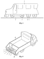
- Figure 1 shows a train carriage 2 riding with wheels 3 on rails 1. It is known that in specific climatic circumstances friction between rails 1 and wheels 3 is reduced to very low levels, which results in difficulties when accelerating the train carriage 2 or when brakes are applied. The reason that friction reduces is not clear but wet and/or oily deposits on the rails 1, which are rolled in on the rails 1 by the wheels 3 play an important role. It has been found that removal of these rolled-in deposits reduces the frequency and/or severeness of the reduced friction conditions. Special vehicles for cleaning the rails have been used for removing the deposits. It is found to be difficult and expensive to let these vehicles clean all tracks regularly as they disturb the normal train service.
- a brush 4 is permanently mounted with a fixed support 5 under the train carriage 2 and during normal use of the train carriage 2 this brush 4 cleans the rails 1.
- the brush 4 is of simple construction and does not need a separate drive for rotating it (see hereunder) several brushes 4 can be mounted under the train carriage 2. This improves the brushing action when a train moves over a track.
- the rails 1 is regularly cleaned at fairly short intervals so that build up of friction reducing deposits is reduced or avoided.
- the brushes 4 are pressed on the rails 1 whereby the circumference of the brush 4 rolls over the rails 1.
- the brushing action of the brush 4 on rails 1 arises from an angle ⁇ between a plane V perpendicular on a rotation-axis 22 of the brush 4 and a direction of movement F, of the train carriage 2 over rails 1, see figure 5. This results in short brushing movements in the direction of the rotation-axis 22.
- These small brushing movements occur only at the location of a springy wire 8 (see figures 2-5) it is advantageous to have for each train on each rails at least four brushes 4 and to have several springy wires 8 side by side in the brush 4.
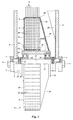
- FIG. 1 the brush 4 is shown in more detail.
- An outer housing ring 18 is welded with a conical housing 19 on a sleeve 13.
- the sleeve 13 is mounted with bearings 16 on shaft 17 and can rotate around the rotation axis 22.
- the axial movement of the bearings 16 is limited by rings 14 which are positioned on the shaft 17 with dowels 15.
- the shaft 17 is positioned in the bracket 5 using caps 7 fastened with bolts 6.
- the bracket 5 is provided with a stiffener 21 for transferring the axial forces to a support beam 24.
- a support ring 12 is fastened for instance by welding on the sleeve 13.
- the support ring 12 is provided with positioning holes 31 and the outer housing ring 18 is provided with the same number of guidance holes 23 of approximately the same diameter.
- the guidance holes 23 can be positioned side by side as shown in figure 4, but they may also be staggered for a more regular distribution.
- a springy wire 8 extends with a wire tip length 27 through the guidance hole 23 of the outer housing ring 18 and is positioned in the positioning hole 31 and supported by the support ring 12.
- the springy wire 8 is provided with one or more bends so that the wire tip length 27 extending through the guidance hole 23 can elastically be reduced to a reduced wire tip length 28 as is shown in figure 3 by the springy wire 8 drawn with interrupted lines.
- the springy wire 8 is provided with one bend forming approximately a semi circle so that all springy wires 8 that extend through guidance holes 23 lying in a plane perpendicular to the rotation axis 22 can be positioned in that plane as well.
- partitioning disks 10 for instance made of thin plastic sheet material, are placed between groups springy wires 8 that extend through holes 23 lying in the plane perpendicular to the rotation axis 22.
- a distance bush 20 is fastened to the conical housing 19.
- a cover 11 is fastened with bolts 9 to the outer housing ring 18 in order to position the springy wires 8.
- the springy wires 8 are made from hardened steel wire and are dimensioned such that applying a force directed to the rotation axis 22 on the wire tip 36, shortens the wire tip length 27 as the springy wire 8 moves through the guidance hole 23.
- the springy wire 8 can freely move in the guidance hole 23. Forces parallel to the rotation axis 22 outside a guidance hole 23 cause it to bend.
- the hardened steel wire has a diameter of 1,5 mm and the force which must be extended on the wire tip 36 in order for the wire tip length 27 to get shorter can be in the range of 3-8 Newton.
- Figure 4 and 5 show the interaction between the brush 4 and rails 1.
- the brush 4 is fastened with bracket 5 to the support beam 24 at the underside of the train carriage 2.
- the height of the support beam 24 is fixed in such a way that the wire tips 36 touch on a top surface 25 of rails 1, whereby the wire tip length 27 is reduced to the reduced wire tip length 28. In this situation there is a contact area 26 between brush 4 and top surface 25.
- this relative movement causes the brush 4 to rotate.
- the brush 4 rotates in a direction R over a contact angle ⁇ from the instant that a wire tip 36 touches the top surface 25 in a location A until the wire tip 36 is free again from the top surface 25 in a location B.
- the contact angle ⁇ is between 30° - 60°, in the embodiment of figure 4 the contact angle ⁇ is approximately 40°.
- the springy wires 8 rotate in a plane of rotation perpendicular to the rotation axis 22, these planes are parallel to a plane V that makes a pitch angle ⁇ with the forward movement F.
- the guidance holes 23 rotate more or less synchronously with the relative movement F of the rails 1.
- the movement of the wire tip 36 over the top surface 25 is illustrated by assuming the wire tip 36 to touch the top surface 25 in position A', in that position the rotation axis is according to line 22', see figure 5, whereby it is the contact area length 26 in front of the shown position of brush 4.
- the wire tip 36 After moving the brush 4 over the contact area length 26 to the position according to figure 5 with the rotation axis 22 the wire tip 36 has moved over a wire tip path 30, due to rotation of the brush over the contact angle ⁇ .
- the wire tip 36 is pressed resiliently against the top surface 25, that the wire tip length 27 can be reduced elastically and that the pitch angle ⁇ has a small value, for instance less than 10-15°.
- the wire tip 36 remains pressed against the top surface 25 and the springy wire 8 bends during the sideways movement of the guidance hole 23.
- the guidance hole 23 moves upwards again and the force with which the wire tip 36 is pressed against the top surface 25 reduces, then the wire tip 36 starts scratching over the top surface 25 until the wire tip 36 is lifted from the top surface in the relief position B.
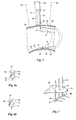
- FIG 6a the relative movement of a springy wire 8 over the top surface 25 is shown in a section view of the rails, whereby a relative guide hole path 34 is shown from the moment a wire tip 36 touches the top surface 25, in start position A where after the guidance hole 23 lowers to a lowest position as the brush 4 rotates, and moves upwards again.
- Wire positions 35 show the springy wire 8 in the start position A when the guidance hole 23 is in its lowest position and when the springy wire 8 is lifted from the top surface in the relief position B.
- wire positions 33 show the same view in a situation whereby the springy wire 8 cannot scratch over the top surface 25 as it is blocked in doing that, for instance because it rests against a side of the rails 1.
- the reduce wire tip length 28 In order to prevent permanent bending of or damage to the springy wires 8 the reduce wire tip length 28 must be chosen long enough so that elastic bending can take place in order to prevent permanent bending and also the pitch angle must not be too great, for instance between 5° to 10°, or a coupling between the springy wires 8 as shown hereafter must be used.
- FIG 7 shows an embodiment whereby each springy wire 8 is provided with a loop 40.
- a coupling wire 41 is inserted through rings formed by the loops 40 of springy wires 8 which are inserted through guidance holes 23 which are lying in a plane through the rotation axis 22. If one or more springy wires 8 are pressed inwards the coupling wire 41 pulls the other springy wires 8 also inwards through the guidance holes 23, which prevents sideways pushing of springy wires 8 that are not pushed inwards by the top surface 26 as shown in figure 6b, and so bending of these springy wires 8 is prevented.
- Figure 8 shows an embodiment of the invention whereby a truck 37 is provided with a salt spreader 38. It has been found that in circumstances whereby a road is covered in a thin layer of ice, that breaking and removing the thin layer by snow removing equipment is difficult. In order to scratch an iced surface so that salt can react better with the ice layer the truck 37 is provided with a roller 39 that is provided with springy wires 8 according to the invention.
Landscapes
- Engineering & Computer Science (AREA)
- Architecture (AREA)
- Civil Engineering (AREA)
- Structural Engineering (AREA)
- Cleaning In General (AREA)
Priority Applications (2)
| Application Number | Priority Date | Filing Date | Title |
|---|---|---|---|
| EP04025877A EP1653005A1 (fr) | 2004-11-01 | 2004-11-01 | Dispositif pour brosser la face supérieure, voiture ferroviaire utilisant ledit dispositif pour nettoyer des voies ferrées et véhicule pourvu d'un tel dispositif |
| EP05077496A EP1653006A3 (fr) | 2004-11-01 | 2005-11-01 | Dispositif pour brosser la face supérieure, voiture ferroviaire utilisant ledit dispositif pour nettoyer des voies ferrées et véhicule pourvu d'un tel dispositif |
Applications Claiming Priority (1)
| Application Number | Priority Date | Filing Date | Title |
|---|---|---|---|
| EP04025877A EP1653005A1 (fr) | 2004-11-01 | 2004-11-01 | Dispositif pour brosser la face supérieure, voiture ferroviaire utilisant ledit dispositif pour nettoyer des voies ferrées et véhicule pourvu d'un tel dispositif |
Publications (1)
| Publication Number | Publication Date |
|---|---|
| EP1653005A1 true EP1653005A1 (fr) | 2006-05-03 |
Family
ID=34927184
Family Applications (1)
| Application Number | Title | Priority Date | Filing Date |
|---|---|---|---|
| EP04025877A Withdrawn EP1653005A1 (fr) | 2004-11-01 | 2004-11-01 | Dispositif pour brosser la face supérieure, voiture ferroviaire utilisant ledit dispositif pour nettoyer des voies ferrées et véhicule pourvu d'un tel dispositif |
Country Status (1)
| Country | Link |
|---|---|
| EP (1) | EP1653005A1 (fr) |
Cited By (1)
| Publication number | Priority date | Publication date | Assignee | Title |
|---|---|---|---|---|
| CN113974477A (zh) * | 2021-11-05 | 2022-01-28 | 江苏南高智能装备创新中心有限公司 | 一种基于物联网的家居机器人 |
Citations (4)
| Publication number | Priority date | Publication date | Assignee | Title |
|---|---|---|---|---|
| WO1988008900A1 (fr) * | 1987-05-11 | 1988-11-17 | Ab Mähler & Söner | Procede et appareil de nettoyage de rails |
| EP0296563A1 (fr) * | 1987-06-26 | 1988-12-28 | Rolba Ag | Dispositif de déblaiement pour surfaces couvertes de neige |
| US5060335A (en) * | 1990-12-28 | 1991-10-29 | Richard Webster | Apparatus for cleaning the surface of a railway rail |
| DE4024291A1 (de) * | 1990-07-31 | 1992-02-13 | Kuepper Weisser Gmbh | Fahrbare kehrvorrichtung |
-
2004
- 2004-11-01 EP EP04025877A patent/EP1653005A1/fr not_active Withdrawn
Patent Citations (4)
| Publication number | Priority date | Publication date | Assignee | Title |
|---|---|---|---|---|
| WO1988008900A1 (fr) * | 1987-05-11 | 1988-11-17 | Ab Mähler & Söner | Procede et appareil de nettoyage de rails |
| EP0296563A1 (fr) * | 1987-06-26 | 1988-12-28 | Rolba Ag | Dispositif de déblaiement pour surfaces couvertes de neige |
| DE4024291A1 (de) * | 1990-07-31 | 1992-02-13 | Kuepper Weisser Gmbh | Fahrbare kehrvorrichtung |
| US5060335A (en) * | 1990-12-28 | 1991-10-29 | Richard Webster | Apparatus for cleaning the surface of a railway rail |
Cited By (2)
| Publication number | Priority date | Publication date | Assignee | Title |
|---|---|---|---|---|
| CN113974477A (zh) * | 2021-11-05 | 2022-01-28 | 江苏南高智能装备创新中心有限公司 | 一种基于物联网的家居机器人 |
| CN113974477B (zh) * | 2021-11-05 | 2022-09-09 | 江苏南高智能装备创新中心有限公司 | 一种基于物联网的家居机器人 |
Similar Documents
| Publication | Publication Date | Title |
|---|---|---|
| US20100258026A1 (en) | Device attached to guided vehicle to remove obstacles on guideway | |
| JP2016055742A (ja) | 除雪装置、車両、及び軌道系交通システム | |
| US7073661B2 (en) | Self cleaning conveyor with roller scraper and debris reduction skirt | |
| EP1653006A2 (fr) | Dispositif pour brosser la face supérieure, voiture ferroviaire utilisant ledit dispositif pour nettoyer des voies ferrées et véhicule pourvu d'un tel dispositif | |
| US9707938B2 (en) | Tire groove cleaning mechanism | |
| JP2010513760A (ja) | レール上を回転する2つの傾斜ローラーによる誘導ユニットのための抗脱出用安全装置 | |
| EP1653005A1 (fr) | Dispositif pour brosser la face supérieure, voiture ferroviaire utilisant ledit dispositif pour nettoyer des voies ferrées et véhicule pourvu d'un tel dispositif | |
| JP2016049936A (ja) | 除雪装置、車両、及び軌道系交通システム | |
| US4781121A (en) | System for enhancing traction and energy efficiency in trains | |
| US5904100A (en) | Method and device to clean three rail model railroad tracks | |
| US20090114775A1 (en) | Junction for Guideways of Vehicles, in Particular of Magnetic Levitation Railways | |
| US4294405A (en) | Traction bag | |
| KR101545967B1 (ko) | 산악 철도용 피니언 기어 승하강 구조 | |
| JP2006078156A (ja) | 煙道の清浄化方法および装置 | |
| EP2964831B1 (fr) | Ensemble jonction de rail | |
| JPH07891A (ja) | トロリ線用塗布装置 | |
| JP2003276604A (ja) | フランジ摩擦低減装置および方法 | |
| JP2577240B2 (ja) | レール塗油除去清掃装置 | |
| JP4657274B2 (ja) | 鉄道分岐器用曲線レール | |
| CN111663820B (zh) | 带有自适应斜坡的移车装置 | |
| JP6167727B2 (ja) | 転炉下清掃設備 | |
| NL1043056B1 (en) | Railway cleaning system and method | |
| JP2007253649A (ja) | 着霜除去装置及び着霜除去方法 | |
| EP1183930A1 (fr) | Dispositif pour séparer la tare de produits agricole et méthode de nettoyage de ce dispositif | |
| CN222648664U (zh) | 一种扫雪装置及车辆 |
Legal Events
| Date | Code | Title | Description |
|---|---|---|---|
| PUAI | Public reference made under article 153(3) epc to a published international application that has entered the european phase |
Free format text: ORIGINAL CODE: 0009012 |
|
| AK | Designated contracting states |
Kind code of ref document: A1 Designated state(s): AT BE BG CH CY CZ DE DK EE ES FI FR GB GR HU IE IS IT LI LU MC NL PL PT RO SE SI SK TR |
|
| AX | Request for extension of the european patent |
Extension state: AL HR LT LV MK YU |
|
| AKX | Designation fees paid | ||
| REG | Reference to a national code |
Ref country code: DE Ref legal event code: 8566 |
|
| STAA | Information on the status of an ep patent application or granted ep patent |
Free format text: STATUS: THE APPLICATION IS DEEMED TO BE WITHDRAWN |
|
| 18D | Application deemed to be withdrawn |
Effective date: 20061104 |