EP1653077A1 - Limitage de fuites pour injecteur - Google Patents
Limitage de fuites pour injecteur Download PDFInfo
- Publication number
- EP1653077A1 EP1653077A1 EP04025371A EP04025371A EP1653077A1 EP 1653077 A1 EP1653077 A1 EP 1653077A1 EP 04025371 A EP04025371 A EP 04025371A EP 04025371 A EP04025371 A EP 04025371A EP 1653077 A1 EP1653077 A1 EP 1653077A1
- Authority
- EP
- European Patent Office
- Prior art keywords
- fuel
- pressure
- conduit
- valve
- intake valve
- Prior art date
- Legal status (The legal status is an assumption and is not a legal conclusion. Google has not performed a legal analysis and makes no representation as to the accuracy of the status listed.)
- Granted
Links
- 239000000446 fuel Substances 0.000 claims abstract description 108
- 238000002485 combustion reaction Methods 0.000 claims abstract description 5
- 239000002828 fuel tank Substances 0.000 claims description 12
- 239000007789 gas Substances 0.000 description 7
- 238000002347 injection Methods 0.000 description 4
- 239000007924 injection Substances 0.000 description 4
- 238000013508 migration Methods 0.000 description 3
- 230000005012 migration Effects 0.000 description 3
- 230000000694 effects Effects 0.000 description 2
- 230000006698 induction Effects 0.000 description 2
- 239000006096 absorbing agent Substances 0.000 description 1
- 239000003054 catalyst Substances 0.000 description 1
- 230000008602 contraction Effects 0.000 description 1
- 238000001816 cooling Methods 0.000 description 1
- 239000003502 gasoline Substances 0.000 description 1
- 238000010438 heat treatment Methods 0.000 description 1
- 239000007788 liquid Substances 0.000 description 1
- 238000000034 method Methods 0.000 description 1
- 238000011045 prefiltration Methods 0.000 description 1
- 230000001052 transient effect Effects 0.000 description 1
- 238000011144 upstream manufacturing Methods 0.000 description 1
Images
Classifications
-
- F—MECHANICAL ENGINEERING; LIGHTING; HEATING; WEAPONS; BLASTING
- F02—COMBUSTION ENGINES; HOT-GAS OR COMBUSTION-PRODUCT ENGINE PLANTS
- F02M—SUPPLYING COMBUSTION ENGINES IN GENERAL WITH COMBUSTIBLE MIXTURES OR CONSTITUENTS THEREOF
- F02M37/00—Apparatus or systems for feeding liquid fuel from storage containers to carburettors or fuel-injection apparatus; Arrangements for purifying liquid fuel specially adapted for, or arranged on, internal-combustion engines
- F02M37/04—Feeding by means of driven pumps
- F02M37/08—Feeding by means of driven pumps electrically driven
- F02M37/10—Feeding by means of driven pumps electrically driven submerged in fuel, e.g. in reservoir
- F02M37/106—Feeding by means of driven pumps electrically driven submerged in fuel, e.g. in reservoir the pump being installed in a sub-tank
Definitions
- the present invention relates to a fuel supply system for a combustion engine, wherein said system comprises at least one fuel injector, a fuel pump and hosing connecting said fuel pump with said at least one fuel injector.
- Fuel injection systems for gasoline engines have been commonly used since the early nineteen seventies, i.a. since electronically controlled fuel injection is a necessity for allowing use of three-way catalysts.
- the principal design described above will keep the pressure during the whole heating sequence of the fuel in the system. When the system is then cooled down the pressure will decrease as a result of the cooling contraction. Compared to the atmospheric pressure, there will be an increasing under pressure in the system until the under pressure reaches the set point of the one way valve in the system/fuel pump. At that stage the one way valve will open and new fuel will be sucked in to the system from the tank.
- US-A-6 438 486 describes another system for reducing fuel vapor emissions.
- This system comprises a fuel vapor absorber placed upstream the fuel injectors, in the intake air stream, and prevents fuel migration from the fuel injectors to the atmosphere. This document does however not mention anything about actually reducing fuel leakage from the injectors, only a method to stop the migration of fuel from the fuel injectors to the atmosphere.
- US-A-6 679 228 describes yet another system for reducing migration of fuel vapors from the fuel injectors to the atmosphere. This document also fails to teach any means for reducing the actual fuel leakage from the fuel injectors.
- the present invention solves the above-mentioned and other problems by providing a gas intake valve connecting a fuel hosing to the atmosphere, wherein the gas intake valve is a one-way valve that prohibits sub-atmospheric pressures in the fuel hosing by allowing gas to enter the fuel hosing.
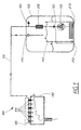
- a fuel supply system 100 according to the present invention is shown.
- the fuel system 100 comprises six fuel injectors 110 connected to a fuel rail 120.
- the fuel rail 120 is connected to a fuel pump 130, situated in a fuel tank 140, by a hosing 150.
- the fuel pump 130 comprises a one-way valve 135, which prevents fuel from flowing from the fuel rail 120 to the tank 140 when the fuel pump 130 is shut off.
- an air intake valve 160 which also is of the one-way type, and a pressure relief valve 170 are connected to the hosing.
- an engine 180 and an internal fuel supply tank 190, fitted with a level keeping ejector pump 200, are shown.
- a pre-filter 210 and a main filter 220 are shown.
- the air let into the fuel supply system will even out the pressure increase due to the expansion of the fuel; as is well known by persons skilled in the art, it is possible to compress gases. It is however not possible to compress liquids. As a consequence, the fuel pressure will be reduced in the system which will reduce the leakage through the injectors.
- the fuel injectors will not be exposed to fuel pressures that vary between positive pressures and sub-atmospheric pressures, since, as mentioned, the air intake valve is of one-way type, and hence will open if negative pressure differences, i.e. lower fuel pressure than atmospheric pressure, occur.
- the air inlet valve opens in the fuel tank. This requires that the fuel level in the fuel tank is lower than the air intake of the air inlet valve; otherwise, the desired effect, namely induction of or gas, will not be achieved. In order to solve the problem with, it might in some cases be advantageous to place the air intake valve outside the fuel tank.
- the opening pressure difference of the air intake valve 160 is lower than the opening pressure difference of the one-way valve 135; otherwise, the desired effect is not achieved, since, in that case, fuel will be drawn in through the one-way valve 135 and the fuel pump 130 from the fuel tank 140.
Landscapes
- Engineering & Computer Science (AREA)
- Chemical & Material Sciences (AREA)
- Combustion & Propulsion (AREA)
- Mechanical Engineering (AREA)
- General Engineering & Computer Science (AREA)
- Fuel-Injection Apparatus (AREA)
Priority Applications (3)
| Application Number | Priority Date | Filing Date | Title |
|---|---|---|---|
| DE602004007394T DE602004007394T2 (de) | 2004-10-26 | 2004-10-26 | Einspritzventilleckstrombegrenzung |
| EP04025371A EP1653077B1 (fr) | 2004-10-26 | 2004-10-26 | Limitage de fuites pour injecteur |
| US11/684,670 US7290534B2 (en) | 2004-10-26 | 2007-03-12 | Injector leakage limitation |
Applications Claiming Priority (1)
| Application Number | Priority Date | Filing Date | Title |
|---|---|---|---|
| EP04025371A EP1653077B1 (fr) | 2004-10-26 | 2004-10-26 | Limitage de fuites pour injecteur |
Publications (2)
| Publication Number | Publication Date |
|---|---|
| EP1653077A1 true EP1653077A1 (fr) | 2006-05-03 |
| EP1653077B1 EP1653077B1 (fr) | 2007-07-04 |
Family
ID=34927107
Family Applications (1)
| Application Number | Title | Priority Date | Filing Date |
|---|---|---|---|
| EP04025371A Expired - Lifetime EP1653077B1 (fr) | 2004-10-26 | 2004-10-26 | Limitage de fuites pour injecteur |
Country Status (3)
| Country | Link |
|---|---|
| US (1) | US7290534B2 (fr) |
| EP (1) | EP1653077B1 (fr) |
| DE (1) | DE602004007394T2 (fr) |
Families Citing this family (2)
| Publication number | Priority date | Publication date | Assignee | Title |
|---|---|---|---|---|
| DE102004027507A1 (de) * | 2004-06-04 | 2005-12-22 | Robert Bosch Gmbh | Kraftstoffeinspritzsystem |
| US11268473B2 (en) * | 2019-11-25 | 2022-03-08 | Ford Global Technologies, Llc | Systems and methods for reducing release of undesired evaporative emissions in plug-in hybrid electric vehicles |
Citations (6)
| Publication number | Priority date | Publication date | Assignee | Title |
|---|---|---|---|---|
| US3731665A (en) | 1970-01-24 | 1973-05-08 | Alfa Romeo Spa | Internal combustion engine, more particularly for motor vehicles, and means for limiting the emission of unburned gases |
| EP0826872A2 (fr) * | 1996-08-26 | 1998-03-04 | Yamaha Hatsudoki Kabushiki Kaisha | Dispositif d'injection de liquide |
| US20020020397A1 (en) * | 2000-06-28 | 2002-02-21 | Begley Chris Clarence | Electronic returnless fuel system |
| US6438486B1 (en) | 2000-09-21 | 2002-08-20 | Ford Global Technologies, Inc. | System and method for minimizing fuel evaporative emissions from an internal combustion engine |
| US6679228B1 (en) | 1999-08-16 | 2004-01-20 | Delphi Technologies, Inc. | Low evaporative emissions integrated air fuel module |
| US20040206338A1 (en) * | 2003-04-15 | 2004-10-21 | Visteon Global Technologies, Inc. | Fuel pressure relief valve |
Family Cites Families (15)
| Publication number | Priority date | Publication date | Assignee | Title |
|---|---|---|---|---|
| US4732131A (en) * | 1986-08-26 | 1988-03-22 | Brunswick Corporation | Fuel line purging device |
| HU217041B (hu) * | 1990-02-27 | 1999-11-29 | Orbital Engine Co. (Australia Pty. Ltd.) | Többhengeres belső égésű motor |
| JPH0658156U (ja) * | 1993-01-13 | 1994-08-12 | 富士重工業株式会社 | 燃料タンクの圧力制御装置 |
| US5398655A (en) * | 1994-01-14 | 1995-03-21 | Walbro Corporation | Manifold referenced returnless fuel system |
| US5711275A (en) * | 1995-09-01 | 1998-01-27 | Nippondenso Co., Ltd. | Fuel supply apparatus for an internal combustion engine |
| US5967120A (en) * | 1996-01-16 | 1999-10-19 | Ford Global Technologies, Inc. | Returnless fuel delivery system |
| DE19628580A1 (de) * | 1996-07-16 | 1998-01-22 | Mannesmann Vdo Ag | Strömungsventil |
| TW419389B (en) | 1996-08-22 | 2001-01-21 | Konami Co Ltd | A game machine |
| US5701869A (en) * | 1996-12-13 | 1997-12-30 | Ford Motor Company | Fuel delivery system |
| AUPP627098A0 (en) * | 1998-09-30 | 1998-10-22 | Orbital Engine Company (Australia) Proprietary Limited | Purge fuel flow rate determination method |
| WO2000047888A1 (fr) * | 1999-02-09 | 2000-08-17 | Hitachi, Ltd. | Pompe d'alimentation en combustible a haute pression faisant partie d'un moteur a combustion interne |
| US6532941B2 (en) * | 2000-08-29 | 2003-03-18 | Delphi Technologies, Inc. | Electronic returnless fuel system |
| DE10236314B4 (de) * | 2001-09-08 | 2005-06-16 | Robert Bosch Gmbh | Einspritzanlage für Brennkraftmaschinen mit verbesserten Starteigenschaften |
| US7066152B2 (en) * | 2004-09-03 | 2006-06-27 | Ford Motor Company | Low evaporative emission fuel system depressurization via solenoid valve |
| US7353807B2 (en) * | 2005-04-19 | 2008-04-08 | Ti Group Automotive Systems, L.L.C. | Jet pump assembly of a fuel system for a combustion engine |
-
2004
- 2004-10-26 DE DE602004007394T patent/DE602004007394T2/de not_active Expired - Lifetime
- 2004-10-26 EP EP04025371A patent/EP1653077B1/fr not_active Expired - Lifetime
-
2007
- 2007-03-12 US US11/684,670 patent/US7290534B2/en active Active
Patent Citations (6)
| Publication number | Priority date | Publication date | Assignee | Title |
|---|---|---|---|---|
| US3731665A (en) | 1970-01-24 | 1973-05-08 | Alfa Romeo Spa | Internal combustion engine, more particularly for motor vehicles, and means for limiting the emission of unburned gases |
| EP0826872A2 (fr) * | 1996-08-26 | 1998-03-04 | Yamaha Hatsudoki Kabushiki Kaisha | Dispositif d'injection de liquide |
| US6679228B1 (en) | 1999-08-16 | 2004-01-20 | Delphi Technologies, Inc. | Low evaporative emissions integrated air fuel module |
| US20020020397A1 (en) * | 2000-06-28 | 2002-02-21 | Begley Chris Clarence | Electronic returnless fuel system |
| US6438486B1 (en) | 2000-09-21 | 2002-08-20 | Ford Global Technologies, Inc. | System and method for minimizing fuel evaporative emissions from an internal combustion engine |
| US20040206338A1 (en) * | 2003-04-15 | 2004-10-21 | Visteon Global Technologies, Inc. | Fuel pressure relief valve |
Also Published As
| Publication number | Publication date |
|---|---|
| DE602004007394T2 (de) | 2008-03-06 |
| EP1653077B1 (fr) | 2007-07-04 |
| US20070144489A1 (en) | 2007-06-28 |
| US7290534B2 (en) | 2007-11-06 |
| DE602004007394D1 (de) | 2007-08-16 |
Similar Documents
| Publication | Publication Date | Title |
|---|---|---|
| US7530336B2 (en) | Intake condensation removal for internal combustion engine | |
| US8528332B2 (en) | Stored compressed air management for improved engine performance | |
| US9234469B2 (en) | Condensate management for motor-vehicle compressed air storage systems | |
| US8297263B2 (en) | Vacuum supply system | |
| US8726891B2 (en) | Stored compressed air management and flow control for improve engine performance | |
| KR102305251B1 (ko) | 배기 가스 재순환 방법 및 시스템 | |
| US9410490B2 (en) | Fuel selection system and method for dual fuel engines | |
| US9228536B2 (en) | Load shedding techniques for dual fuel engines | |
| EP2034168A1 (fr) | Moteur diesel pour éther diméthylique | |
| WO2001000981A1 (fr) | Moteur a combustion possedant une recirculation des gaz d'echappement | |
| JP2002098019A (ja) | 燃料供給装置 | |
| JP5989406B2 (ja) | 燃料圧力制御装置 | |
| US6055962A (en) | Fuel system for an internal combustion engine | |
| EP1653077B1 (fr) | Limitage de fuites pour injecteur | |
| US9366206B2 (en) | Fuel-air separator and pulse dampener | |
| WO2018113988A1 (fr) | Moteur à combustion interne | |
| WO1998025012A1 (fr) | Derivation chauffee de refroidisseur secondaire air-air a soupape de commutation a detection de charge | |
| US20160348605A1 (en) | Fuel delivery system | |
| US20250188860A1 (en) | Diesel exhaust fluid tank conduit connected to air compressor and method | |
| RU2067207C1 (ru) | Двигатель внутреннего сгорания | |
| US10030611B2 (en) | Fuel delivery system | |
| US20160341134A1 (en) | Fuel delivery system | |
| KR20090016010A (ko) | 천연가스 터보챠저 인터쿨러 엔진 시스템 | |
| JP2024047856A (ja) | 内燃機関の始動制御装置 | |
| US20120067032A1 (en) | Particulate filter regeneration |
Legal Events
| Date | Code | Title | Description |
|---|---|---|---|
| PUAI | Public reference made under article 153(3) epc to a published international application that has entered the european phase |
Free format text: ORIGINAL CODE: 0009012 |
|
| AK | Designated contracting states |
Kind code of ref document: A1 Designated state(s): AT BE BG CH CY CZ DE DK EE ES FI FR GB GR HU IE IT LI LU MC NL PL PT RO SE SI SK TR |
|
| AX | Request for extension of the european patent |
Extension state: AL HR LT LV MK |
|
| RAP1 | Party data changed (applicant data changed or rights of an application transferred) |
Owner name: FORD GLOBAL TECHNOLOGIES, LLC. |
|
| RIN1 | Information on inventor provided before grant (corrected) |
Inventor name: FISCHER, KJELL |
|
| 17P | Request for examination filed |
Effective date: 20061026 |
|
| GRAP | Despatch of communication of intention to grant a patent |
Free format text: ORIGINAL CODE: EPIDOSNIGR1 |
|
| AKX | Designation fees paid |
Designated state(s): DE GB SE |
|
| GRAS | Grant fee paid |
Free format text: ORIGINAL CODE: EPIDOSNIGR3 |
|
| GRAA | (expected) grant |
Free format text: ORIGINAL CODE: 0009210 |
|
| AK | Designated contracting states |
Kind code of ref document: B1 Designated state(s): DE GB SE |
|
| REG | Reference to a national code |
Ref country code: GB Ref legal event code: FG4D |
|
| REF | Corresponds to: |
Ref document number: 602004007394 Country of ref document: DE Date of ref document: 20070816 Kind code of ref document: P |
|
| REG | Reference to a national code |
Ref country code: SE Ref legal event code: TRGR |
|
| PLBE | No opposition filed within time limit |
Free format text: ORIGINAL CODE: 0009261 |
|
| STAA | Information on the status of an ep patent application or granted ep patent |
Free format text: STATUS: NO OPPOSITION FILED WITHIN TIME LIMIT |
|
| 26N | No opposition filed |
Effective date: 20080407 |
|
| REG | Reference to a national code |
Ref country code: GB Ref legal event code: 732E Free format text: REGISTERED BETWEEN 20111020 AND 20111025 |
|
| REG | Reference to a national code |
Ref country code: DE Ref legal event code: R082 Ref document number: 602004007394 Country of ref document: DE Representative=s name: VOSSIUS & PARTNER, DE |
|
| REG | Reference to a national code |
Ref country code: DE Ref legal event code: R081 Ref document number: 602004007394 Country of ref document: DE Owner name: VOLVO CAR CORPORATION, SE Free format text: FORMER OWNER: FORD GLOBAL TECHNOLOGIES, LLC, DEARBORN, MICH., US Effective date: 20120207 Ref country code: DE Ref legal event code: R082 Ref document number: 602004007394 Country of ref document: DE Representative=s name: VOSSIUS & PARTNER PATENTANWAELTE RECHTSANWAELT, DE Effective date: 20120207 |
|
| PGFP | Annual fee paid to national office [announced via postgrant information from national office to epo] |
Ref country code: GB Payment date: 20141015 Year of fee payment: 11 |
|
| PGFP | Annual fee paid to national office [announced via postgrant information from national office to epo] |
Ref country code: DE Payment date: 20151021 Year of fee payment: 12 |
|
| PGFP | Annual fee paid to national office [announced via postgrant information from national office to epo] |
Ref country code: SE Payment date: 20151027 Year of fee payment: 12 |
|
| GBPC | Gb: european patent ceased through non-payment of renewal fee |
Effective date: 20151026 |
|
| PG25 | Lapsed in a contracting state [announced via postgrant information from national office to epo] |
Ref country code: GB Free format text: LAPSE BECAUSE OF NON-PAYMENT OF DUE FEES Effective date: 20151026 |
|
| REG | Reference to a national code |
Ref country code: DE Ref legal event code: R119 Ref document number: 602004007394 Country of ref document: DE |
|
| PG25 | Lapsed in a contracting state [announced via postgrant information from national office to epo] |
Ref country code: DE Free format text: LAPSE BECAUSE OF NON-PAYMENT OF DUE FEES Effective date: 20170503 |
|
| PG25 | Lapsed in a contracting state [announced via postgrant information from national office to epo] |
Ref country code: SE Free format text: LAPSE BECAUSE OF NON-PAYMENT OF DUE FEES Effective date: 20161027 |