EP1653085A1 - Compresseur rotatif multi-étagé à capacité variable - Google Patents
Compresseur rotatif multi-étagé à capacité variable Download PDFInfo
- Publication number
- EP1653085A1 EP1653085A1 EP05012405A EP05012405A EP1653085A1 EP 1653085 A1 EP1653085 A1 EP 1653085A1 EP 05012405 A EP05012405 A EP 05012405A EP 05012405 A EP05012405 A EP 05012405A EP 1653085 A1 EP1653085 A1 EP 1653085A1
- Authority
- EP
- European Patent Office
- Prior art keywords
- valve
- cylinder
- sliding valve
- suction
- hole
- Prior art date
- Legal status (The legal status is an assumption and is not a legal conclusion. Google has not performed a legal analysis and makes no representation as to the accuracy of the status listed.)
- Granted
Links
- 230000006835 compression Effects 0.000 claims abstract description 85
- 238000007906 compression Methods 0.000 claims abstract description 85
- 238000005096 rolling process Methods 0.000 claims abstract description 33
- 238000004891 communication Methods 0.000 claims abstract description 19
- 239000003507 refrigerant Substances 0.000 claims description 69
- 239000007788 liquid Substances 0.000 claims description 2
- 230000000694 effects Effects 0.000 abstract description 5
- 239000007789 gas Substances 0.000 description 27
- 238000000034 method Methods 0.000 description 8
- 230000001276 controlling effect Effects 0.000 description 5
- 238000005299 abrasion Methods 0.000 description 4
- 230000008859 change Effects 0.000 description 4
- 238000004519 manufacturing process Methods 0.000 description 4
- 230000003247 decreasing effect Effects 0.000 description 3
- 238000006073 displacement reaction Methods 0.000 description 3
- 230000008569 process Effects 0.000 description 3
- CURLTUGMZLYLDI-UHFFFAOYSA-N Carbon dioxide Chemical compound O=C=O CURLTUGMZLYLDI-UHFFFAOYSA-N 0.000 description 2
- 230000000903 blocking effect Effects 0.000 description 2
- 230000008014 freezing Effects 0.000 description 2
- 238000007710 freezing Methods 0.000 description 2
- 239000000126 substance Substances 0.000 description 2
- 238000010792 warming Methods 0.000 description 2
- ZAMOUSCENKQFHK-UHFFFAOYSA-N Chlorine atom Chemical compound [Cl] ZAMOUSCENKQFHK-UHFFFAOYSA-N 0.000 description 1
- CBENFWSGALASAD-UHFFFAOYSA-N Ozone Chemical compound [O-][O+]=O CBENFWSGALASAD-UHFFFAOYSA-N 0.000 description 1
- 238000004378 air conditioning Methods 0.000 description 1
- 229910002092 carbon dioxide Inorganic materials 0.000 description 1
- 239000001569 carbon dioxide Substances 0.000 description 1
- 230000015556 catabolic process Effects 0.000 description 1
- 229910052801 chlorine Inorganic materials 0.000 description 1
- 239000000460 chlorine Substances 0.000 description 1
- 230000006378 damage Effects 0.000 description 1
- 238000006731 degradation reaction Methods 0.000 description 1
- 238000010586 diagram Methods 0.000 description 1
- 230000004907 flux Effects 0.000 description 1
- 230000006872 improvement Effects 0.000 description 1
- 238000012986 modification Methods 0.000 description 1
- 230000004048 modification Effects 0.000 description 1
- 230000001105 regulatory effect Effects 0.000 description 1
- 238000011160 research Methods 0.000 description 1
- 230000004044 response Effects 0.000 description 1
Images



Classifications
-
- F—MECHANICAL ENGINEERING; LIGHTING; HEATING; WEAPONS; BLASTING
- F04—POSITIVE - DISPLACEMENT MACHINES FOR LIQUIDS; PUMPS FOR LIQUIDS OR ELASTIC FLUIDS
- F04C—ROTARY-PISTON, OR OSCILLATING-PISTON, POSITIVE-DISPLACEMENT MACHINES FOR LIQUIDS; ROTARY-PISTON, OR OSCILLATING-PISTON, POSITIVE-DISPLACEMENT PUMPS
- F04C23/00—Combinations of two or more pumps, each being of rotary-piston or oscillating-piston type, specially adapted for elastic fluids; Pumping installations specially adapted for elastic fluids; Multi-stage pumps specially adapted for elastic fluids
- F04C23/001—Combinations of two or more pumps, each being of rotary-piston or oscillating-piston type, specially adapted for elastic fluids; Pumping installations specially adapted for elastic fluids; Multi-stage pumps specially adapted for elastic fluids of similar working principle
-
- F—MECHANICAL ENGINEERING; LIGHTING; HEATING; WEAPONS; BLASTING
- F04—POSITIVE - DISPLACEMENT MACHINES FOR LIQUIDS; PUMPS FOR LIQUIDS OR ELASTIC FLUIDS
- F04C—ROTARY-PISTON, OR OSCILLATING-PISTON, POSITIVE-DISPLACEMENT MACHINES FOR LIQUIDS; ROTARY-PISTON, OR OSCILLATING-PISTON, POSITIVE-DISPLACEMENT PUMPS
- F04C28/00—Control of, monitoring of, or safety arrangements for, pumps or pumping installations specially adapted for elastic fluids
- F04C28/10—Control of, monitoring of, or safety arrangements for, pumps or pumping installations specially adapted for elastic fluids characterised by changing the positions of the inlet or outlet openings with respect to the working chamber
- F04C28/12—Control of, monitoring of, or safety arrangements for, pumps or pumping installations specially adapted for elastic fluids characterised by changing the positions of the inlet or outlet openings with respect to the working chamber using sliding valves
- F04C28/125—Control of, monitoring of, or safety arrangements for, pumps or pumping installations specially adapted for elastic fluids characterised by changing the positions of the inlet or outlet openings with respect to the working chamber using sliding valves with sliding valves controlled by the use of fluid other than the working fluid
-
- F—MECHANICAL ENGINEERING; LIGHTING; HEATING; WEAPONS; BLASTING
- F04—POSITIVE - DISPLACEMENT MACHINES FOR LIQUIDS; PUMPS FOR LIQUIDS OR ELASTIC FLUIDS
- F04C—ROTARY-PISTON, OR OSCILLATING-PISTON, POSITIVE-DISPLACEMENT MACHINES FOR LIQUIDS; ROTARY-PISTON, OR OSCILLATING-PISTON, POSITIVE-DISPLACEMENT PUMPS
- F04C18/00—Rotary-piston pumps specially adapted for elastic fluids
- F04C18/30—Rotary-piston pumps specially adapted for elastic fluids having the characteristics covered by two or more of groups F04C18/02, F04C18/08, F04C18/22, F04C18/24, F04C18/48, or having the characteristics covered by one of these groups together with some other type of movement between co-operating members
- F04C18/34—Rotary-piston pumps specially adapted for elastic fluids having the characteristics covered by two or more of groups F04C18/02, F04C18/08, F04C18/22, F04C18/24, F04C18/48, or having the characteristics covered by one of these groups together with some other type of movement between co-operating members having the movement defined in group F04C18/08 or F04C18/22 and relative reciprocation between the co-operating members
- F04C18/356—Rotary-piston pumps specially adapted for elastic fluids having the characteristics covered by two or more of groups F04C18/02, F04C18/08, F04C18/22, F04C18/24, F04C18/48, or having the characteristics covered by one of these groups together with some other type of movement between co-operating members having the movement defined in group F04C18/08 or F04C18/22 and relative reciprocation between the co-operating members with vanes reciprocating with respect to the outer member
- F04C18/3562—Rotary-piston pumps specially adapted for elastic fluids having the characteristics covered by two or more of groups F04C18/02, F04C18/08, F04C18/22, F04C18/24, F04C18/48, or having the characteristics covered by one of these groups together with some other type of movement between co-operating members having the movement defined in group F04C18/08 or F04C18/22 and relative reciprocation between the co-operating members with vanes reciprocating with respect to the outer member the inner and outer member being in contact along one line or continuous surfaces substantially parallel to the axis of rotation
- F04C18/3564—Rotary-piston pumps specially adapted for elastic fluids having the characteristics covered by two or more of groups F04C18/02, F04C18/08, F04C18/22, F04C18/24, F04C18/48, or having the characteristics covered by one of these groups together with some other type of movement between co-operating members having the movement defined in group F04C18/08 or F04C18/22 and relative reciprocation between the co-operating members with vanes reciprocating with respect to the outer member the inner and outer member being in contact along one line or continuous surfaces substantially parallel to the axis of rotation the surfaces of the inner and outer member, forming the working space, being surfaces of revolution
Definitions
- the present invention relates to a rotary compressor performing multi-stage compression, and more particularly, to a multi-stage rotary compressor capable of optimizing compression efficiency using all compression units.
- a compressor is a device that increases pressure by compressing the air, a refrigerant gas or other specific gases upon receiving power from a power generator such as an electric motor, and is being used throughout industries.
- the compressor may be divided into a positive displacement compressor and a turbo compressor according to how to compress.
- the positive displacement compressor performs compression by a compression method in which pressure is increased through a volume decreased, and the turbo compressor performs compression by converting kinetic energy of gas into pressure energy.
- a rotary compressor which is a kind of positive displacement compressor, is commonly used for an air conditioning apparatus such as an air-conditioner. In response to demands for air-conditioners having various functions, the rotary compressor that can change its capacity is being required in these days.
- the rotary compressor has used a refrigerant containing a CFC-based chlorine.
- a refrigerant is known as a factor causing destruction of the ozone layer, which results in global warming.
- its use is legally regulated and extensive researches have been made for an alternative refrigerant with respect to the existing refrigerant.
- Carbon dioxide is expected as an alternative refrigerant.
- the global warming leads issues of improvement of energy efficiency of a device as well as issues of the alternative of the existing refrigerant.
- Figure 1 is a sectional view showing one example of the conventional multiple-stage rotary compressor.
- the conventional multiple-stage rotary compressor includes: a casing 1 at which two gas suction pipes 30 and 31 and a gas discharge pipe 40 are installed to communicate with each other; a motor unit 2 installed at an upper side of the casing 1 and including a stator 3 and a rotor 4 for generating a rotary force; and a first compression unit 10 and a second compressor unit 20 installed at upper and lower portions of a lower side of the casing 1 and respectively compressing a refrigerant upon receiving a rotary force generated from the motor unit 2 by a rotary shaft 5.
- One accumulator 6 for separating liquefied refrigerant from a suction refrigerant is installed between the gas suction pipes 30 and 31 and between the compression units 10 and 20.
- the first gas suction pipe 30 supplies a refrigerant to a first cylinder 11 by being connected to a first suction port 17, and the second gas suction pipe 31 supplies a refrigerant to a second cylinder 21 by being connected to a second suction port 27.
- the first compression unit 10 includes: a first cylinder 11 formed as a ring shape and installed inside the casing 1; an upper bearing 12 and a middle bearing 13 covering both upper and lower sides of the first cylinder 11, forming a first inner space 19 together, and supporting the rotary shaft 5 in radial and axial directions; a first rolling piston 14 rotatably coupled to an upper eccentric portion of the rotary shaft 5 and orbiting in a first internal space 19 of the first cylinder 11 to thereby compress a refrigerant; a first vane (not shown) coupled to the first cylinder to be movable in a radial direction so as to pressingly contact with an outer circumferential surface of the first rolling piston 14, and dividing the first inner space 19 of the first cylinder 11 into a first suction chamber and a first compression chamber; and a first discharge valve 15 coupled to a front end of a first discharge port 16 provided at the upper bearing 12 to open or close the first discharge port 16, for controlling the discharge of a refrigerant gas.
- the second compression unit 20 includes: a second cylinder 21 formed as a ring shape and installed under the first cylinder 11 inside the casing 1; a middle bearing 13 and a lower bearing 22 covering both upper and lower sides of the second cylinder 21, forming a second inner space together, and supporting the rotary shaft 5 in a radial direction and an axial direction; a second rolling piston 23 rotatably coupled to a lower eccentric portion of the rotary shaft 5, and orbiting in the second inner space of the second cylinder 21 to compress a refrigerant; a second vane (not shown) coupled to the second cylinder 21 to be movable in a radial direction so as to pressingly contact with an outer circumferential surface of the second rolling piston 23, and dividing the second inner space 29 into a second suction chamber and a second compression chamber; and a second discharge valve 24 coupled to a front end of a second discharge port 26 provided at the lower bearing 22 to open or close the second discharge port 26, for controlling the discharge of a refrigerant gas discharged from the second compression
- Such an ordinary multi-stage rotary compressor sequentially performs suction, compression and discharge of a refrigerant as the rolling piston contacts with an inner diameter of the cylinder at one point.
- the compression units are respectively driven.
- the capacity of the compressor would be the sum total of refrigerant discharged from each compression unit.
- saving mode refrigerants sucked into some compression units are cut off, or the vane moves back and is fixed by a piece or the like, thereby removing a boundary between the suction chamber and the compression chamber, so that the rolling piston does not compress refrigerant but is idled.
- the capacity of the refrigerant is changed by speed changes using an inverter motor having a control drive as a driving unit.
- the structure of the ordinary rotary compressor and a driving method therefor have the following problems.
- the method in which the vane is moved back and fixed in the saving mode has problems that a special part such as a piece or the like and a space where the part is mounted are undesirably required, and the number of manufacturing processes increases.
- a surface of the vane may be damaged as time goes on, and reliability issues such as abrasion, foreign substance generations and the like may be caused.
- an object of the present invention is to provide a multi-stage rotary compressor capable of maximizing compressing efficiency using all compression units, changing a capacity in operation and reducing the amount of consumed power and abrasion between parts.
- an apparatus for changing capacity of a multi-stage compressor comprising: a first cylinder provided with a first suction and a first discharge port, and divided into a first suction chamber and a first compression chamber by a first rolling piston which orbits and a first vane which makes a linear movement in contact with the first rolling piston; a second cylinder provided with a second suction port and a second discharge port, and divided into a second suction chamber and a second compression chamber by a second rolling piston which orbits and a second vane which makes a linear movement in contact with the second rolling piston; a middle bearing inserted between the first cylinder and the second cylinder, having a bypass hole to allow communication between the compression chambers of the first cylinder and the second cylinder, and having a valve hole for communication in the middle of the bypass hole; a sliding valve slidingly coupled to the valve hole of the middle bearing, and selectively opening or closing the bypass hole
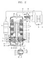
- Figure 2 is a sectional view showing a multi-stage rotary compressor in accordance with a first embodiment of the present invention.
- the multi-stage rotary compressor in accordance with the present invention includes: a casing 1 at which a plurality of gas suction pipes 30 and 31 and a gas discharge pipe 40 are installed to communicate with each other; a motor unit 2 installed at an upper side of the casing and generating a rotary force; a first compression unit 10 and a second compression unit 20 installed at a lower side of the casing 1 in a multi-stage, for respectively compressing refrigerants upon receiving a rotary force, which is generated at the motor unit 2, by the rotary shaft 5; a first sliding valve 121 selectively communicating with the two compression units 10 and 20, for selectively changing a capacity of the compressor; and a first pressure switching unit 160 selectively supplying a high pressure refrigerant gas to the back of the first sliding valve 121, for independently controlling the opening/closing operation of the first sliding valve 121.
- the motor unit 2 includes: a stator 3 fixed in the casing 1 and receiving power from the outside; and a rotor 4 disposed inside the stator 3 with a certain air gap therebetween and rotating, interworking with the stator 3.
- the first compression unit 10 includes: a first cylinder 11 formed as a ring shape, installed inside the casing 1 and having therein a first suction port 17 through which a refrigerant is sucked; an upper bearing 12 and a middle bearing 110 covering both upper and lower sides of the first cylinder 11, forming a first inner space 19 together, and supporting the rotary shaft 5 in a radial direction and an axial direction; a first rolling piston 14 rotatably coupled to an upper eccentric portion of the rotary shaft 5, orbiting in the first inner space 19 of the first cylinder 11 to thereby compress a refrigerant; a first vane (not shown) movably coupled to the first cylinder 1 in a radial direction so as to pressingly contact with an outer circumferential surface of the first rolling piston 14, and dividing the first inner space 19 into a first suction chamber and a first compression chamber; and a first discharge valve 15 coupled to a front end of a first discharge port 16 provided at a central portion of the upper bearing 12 to open or close the first
- Th inner space 19 of the first cylinder 11 may have the same volume as that of an inner space 29 of a second cylinder 21 to be described later. However, the volume of the inner space 19 may be different from that of the inner space 29.
- the second compression unit 20 includes: a second cylinder 21 formed as a ring shape, installed under the first cylinder 11 in the casing 1,and having therein a second suction port 27 through which a refrigerant is sucked; a middle bearing 110 and a lower bearing 22 covering both upper and lower sides of the second cylinder 21, forming a second inner space 29 together, and supporting the rotary shaft 5 in a radial direction and an axial direction; a second rolling piston 23 rotatably coupled to a lower eccentric portion of the rotary shaft 5, and orbiting in the second inner space 29 of the second cylinder 21 to thereby compress a refrigerant; a second vane (not shown) movably coupled to the second cylinder in a radial direction so as to pressingly contact with an outer circumferential surface of the second rolling piston 23, and dividing the second inner space 29 into a second suction chamber and a second compression chamber; and a second discharge valve 24 coupled to a front end of the second discharge port 26 provided at a central portion of the lower bearing
- first vane and second vane are disposed side by side in a horizontal direction
- first suction port 17 and the second suction port 27 are also disposed side by side in a horizontal direction
- first discharge port 16 and the second discharge port 26 are disposed collinearly in a vertical direction.
- the middle bearing 110 is formed as a disc shape having at its center a shaft hole 111 through which the rotary shaft 5 penetrates.
- a bypass hole 114 is penetratingly formed at the middle bearing 110 in an axial direction, so that the inner spaces 19 and 29 of the first cylinder 11 and the second cylinder 21 communicate with each other.
- the first bypass hole 114 is preferably formed to allow the compression chambers of the first and second inner spaces 19 and 29 to communicate with each other.
- a first valve hole 112 communicating with the first bypass hole 114 is formed at the middle bearing 110 in a radial direction, so that the first sliding valve 121 is slidingly coupled thereto.
- the pressure switching unit 160 is a kind of pilot valve, and includes: a first switching valve housing 165 provided with a high pressure inlet 162, a low pressure inlet 163 and a common outlet 164; a first switching valve 166 slidingly coupled inside the first switching valve housing 165 and selectively connecting the high pressure inlet 162 with the common outlet 164 or the low pressure inlet 163 with the common outlet 164; a first electromagnet 167 installed at one side of the first switching valve housing 165 and moving the first switching valve 166 by applied power; and a first switching spring 168 for restoring the first switching valve 166 when the power applied to the first electromagnet 167 is cut off.
- the high pressure inlet 162 is connected to the gas discharge pipe 40 by a first high pressure connection pipe so that high pressure formed in the casing 1 is supplied to the high pressure inlet 162, and, by a first low pressure connection pipe 173, the low pressure inlet 163 is connected to the middle of a connection pipe 33 through which a refrigerant is sucked to an accumulator 6 for separating gas-liquid from refrigerants, so that low pressure is supplied to the low pressure inlet 163.
- a first common connection pipe 174 connects the common outlet 164 to a back side of the first sliding valve 121 so that a high pressure atmosphere or a low pressure atmosphere is supplied to the back side.
- Figures 3 and 4 are sectional views partially showing an apparatus for changing a capacity of the multi-stage rotary compressor in accordance with the present invention.
- a valve stopping projection 116 is stepped at an inner side of an inner circumferential surface of the first valve hole 112 in order to restrict a movement of the first sliding valve 121 by stopping a stopping protrusion 123 formed at the first sliding valve 121 in the closing of the first sliding valve 121.
- a valve stopper 131 is insertedly coupled into the valve hole 112 from the outside in order to restrict a movement of the first sliding valve 121 by stopping the stopping projection 123 when the first sliding valve 121 opens the first bypass hole 114.
- the valve stopper 131 has a communication hole 133 connected to the common connection pipe 174 of the first pressure switching unit 160 so that high pressure or low pressure refrigerant gas can be supplied to the back of the first sliding valve 121.
- a spring fixing step 135 with a screw thread (not shown) is formed at an inner circumferential surface of the communication hole 133 so that a valve spring 141 to be described later is screw-threaded thereto.
- the first sliding valve is formed as a cylindrical body whose inner diameter side (hereinafter, referred to as a front end) is closed.
- a front end At an outer circumferential surface of the other end of the first sliding valve 121 (hereinafter, referred to as a rear end), the stopping protrusion 123 is protrudingly formed to restrict a moving distance of the first sliding valve 121 by being caught by the valve stopping projection 116.
- a spring fixing step 125 with a screw thread (not shown) for fixing the valve spring 141 by means of screw-threading is stepped at an inner circumferential surface of the front end of the first sliding valve 121.
- the valve spring 141 may be substituted by another elastic member.
- a valve spring 141 is installed inside the first sliding valve.
- the valve spring is an extended spring that is compressed when pressure applied to its one side through the communication hole 133 and pressure applied to its other side through the first bypass hole 114 are balanced, so that the first sliding valve 121 is pulled toward the valve stopper 131 to open the first bypass hole 114.
- the valve spring 141 is extended so that the first sliding valve 121 closes the first bypass hole 114.
- the apparatus for changing a capacity of the rotary compressor in accordance with the present invention is operated as follows.
- first and second vanes (not shown) divides the inner space 19 and 29 into a suction chamber and a compression chamber. Refrigerants are sucked through the suction ports 17 and 27 formed at the suction chambers, are compressed by a volume change in the compression chambers, and are discharged into the casing 1 through the discharge ports 16 and 26.
- the discharge refrigerants are spurted to a condenser 7 of a freezing cycle through the gas discharge pipe 40, and pass through the expansion apparatus 8 and the evaporator 9 in order, and then are sucked again into the internal space 19 and 29 of each cylinder 11 and 21 through the gas suction pipes 30 and 31. And such processes are repeated.
- the multi-stage rotary compressor operates, changing its capacity according to an operational state of an air conditioner using the same.
- a power mode and a saving mode will now be explained, respectively.
- the multi-stage rotary compressor operates in a power mode when the first compression unit 10 and the second compression unit 20 operate, separately.
- an electromagnet 167 of the first pressure switching unit 160 a pilot valve, is turned on, so that the first switching valve 166 overcomes the switching spring 168 and allows communication between the high pressure inlet 162 and the common outlet 164.
- the high pressure inlet 162 is connected to the first high pressure connection pipe 172, and the first high pressure connection pipe 172 is connected to the gas discharge pipe 40. For this reason, the discharge pressure is applied to one side of the first sliding valve 121 through the first common connection pipe 174 and the communication hole 133.
- each cylinder 11 and 21 is applied to the other side of the first sliding valve 121 through the first bypass hole 114, and the inner pressure is smaller than the discharge pressure. Therefore, the valve spring 140 is extended, moving the first sliding valve 121 forward so as to block the first bypass hole 114.
- a refrigerant gas sucked to the first cylinder 11 and a refrigerant gas sucked to the second cylinder 21 are not mixed together but are compressed and discharged into the casing 1, respectively.
- the multi-stage rotary compressor operates in a saving mode.
- the electromagnet 167 of the first pressure switching unit 160 is turned off to allow communication between the low pressure inlet 163 and the common outlet 164.
- the low pressure inlet 163 is connected to the first low pressure connection pipe 173 and the connection pipe 33 so that a low pressure refrigerant flow therein.
- Such a refrigerant is supplied to a back surface of the first sliding valve 121 through the communication hole 13.
- the first sliding valve 121 moves backward by a compression force of the valve spring 141 to thereby open the first bypass hole 114.
- the compression chambers (not shown) of the internal spaces 19 of the cylinders 11 and 21 communicate with each other.
- the first rolling piston 14 and the second rolling piston 23 have been disposed with a phase difference of 180 degrees, and a volume and internal pressure of the first compression chamber where the first bypass hole 114 is exposed, of the inner space 19 of the first compression unit 10, are different from those of the second compression chamber where the first bypass hole 114 is exposed, of the inner space 29 of the second compression unit 20. Namely, if the pressure of the first compression chamber is greater than that of the second compression chamber, the refrigerants move to the second compression chamber from the first compression chamber through the first bypass hole 114 and thus cannot be compressed.
- the refrigerants move from the second compression chamber to the first compression chamber through the first bypass hole 114, and thus cannot be compressed. Then, from a position where the second rolling piston 23 or the eccentric portion closes the first bypass hole 114, the refrigerants are no longer bypassed but are compressed and then discharged.
- each compression unit 10 and 20 When each compression unit 10 and 20 operates in the saving mode, the refrigerants are not compressed as much as an entire volume of each compression chamber, and some are bypassed from a high pressure compression chamber to a low pressure compression chamber. Only some of the refrigerants are compressed and discharged. Such processes are repeated, thereby decreasing a discharge capacity of the refrigerants. In such a manner, the change of the capacity in the power mode or in the saving mode can be achieved.
- a bypass hole is formed in plurality so that multi-stage capacity changes can be achieved.
- Figure 5 is a partially cut-out view showing a multi-stage rotary compressor in accordance with the second embodiment of the present invention
- Figure 6 is an exploded perspective view showing a middle bearing in accordance with the second embodiment of the present invention.
- Like reference numerals designate like or corresponding parts to the first embodiment.
- the middle bearing 210 is formed as a disc shape having at its center a shaft hole 311 through which a rotary shaft 5 penetrates, and a second bypass hole 234 and a third bypass hole 235 are penetratingly formed at one side of a vane in an axial direction.
- the second bypass hole 234 and the third bypass hole 235 are formed in turn along a rotating direction of the rotary shaft on the basis of the vane.
- the second bypass hole 234 is formed in the vicinity of 160 degrees from the first vane along a rotating direction of the rotary shaft, and the third bypass hole may be formed in the vicinity of 240 degrees.
- a second valve hole 243 and a third valve hole 244 having predetermined depths are formed to communicate with the second bypass hole 234 and the third bypass hole 235 in a radial direction, and a second sliding valve 231 and a third sliding valve 232 are slidingly coupled thereto, respectively.
- the second pressure switching unit 211 is a kind of pilot valve, and includes a second switching valve housing 215 at which a high pressure inlet 212, a low pressure inlet 213 and a common outlet 214 are formed; a second switching valve 216 slidingly coupled inside the second switching valve housing 215, for selectively connecting the high pressure inlet 212 with the common outlet 214 or the low pressure inlet 213 with the common outlet 214; a second electromagnet 217 installed at one side of the second switching valve housing 215, for moving the second switching valve 216 by applied power; and a second switching spring 218 for restoring the second switching valve 216 when the power applied to the second electromagnet 217 is cut off.
- the high pressure inlet 212 is connected to the gas discharge pipe 40 by a second high pressure connection pipe 312 so that high pressure formed in the casing 1 can be supplied to the high pressure inlet 212, and by a second low pressure connection pipe 313, the low pressure inlet 213 is connected to the middle of a connection pipe 33 connected to each refrigerant suction pipe 30 and 31 so that low pressure is supplied to the low pressure inlet 213.
- the common outlet 213 is connected to a back side of a second sliding valve 231 by a second common connection pipe 314 so that an high pressure or low pressure atmosphere is supplied to the back side.
- the third rear pressure switching unit 221 is a kind of pilot valve, and includes a third switching valve housing 225 at which a high pressure inlet 222, a low pressure inlet 223 and a common outlet 224 are formed; a third switching valve 226 slidingly coupled inside the third switching valve housing 225, for selectively connecting the high pressure inlet 222 or the low pressure inlet 223 to the common outlet 224; a third electromagnet 227 installed at one side of the third switching valve housing 225, for moving the third switching valve 226 by applied power; and a third switching spring 228 for restoring the third switching valve 226 when power applied to the third electromagnet 227 is cut off.
- the high pressure inlet 222 is connected to the gas discharge pipe 40 by a third high pressure connection pipe 322 so that high pressure formed in a casing 1 is supplied to the high pressure inlet 222, and by a third low pressure connection pipe 323, the low pressure inlet 223 is connected to the middle of the connection pipe 33 connected to each refrigerant suction pipe 30 and 31 so that low pressure is supplied to the low pressure inlet 223.
- the common outlet 224 is connected to a rear side of a third sliding valve 232 by a third common connection pipe 324 so that a high pressure or low pressure atmosphere is supplied to the back side.
- a valve stopping projection 236 is stepped at the inside of an inner circumferential surface of the second valve hole 243 in order to restrict a movement of the second sliding valve 231 by stopping a stopping protrusion 223 of the second sliding valve 231 in the closing of the second sliding valve 231.
- a valve stopper (not shown) is insertedly coupled to the valve hole 243 from the outside in order to restrict a movement of the second sliding valve 231 by stopping the stopping protrusion 223 in the opening of the second sliding valve 231.
- a valve stopping projection 237 is stepped at the inside of an inner circumferential surface of the third valve hole 244 in order to restrict a movement of the third sliding valve 232 by stopping a stopping protrusion 233 of the third sliding valve 232 in the closing of the third sliding valve 232.
- a valve stopper (not shown) is insertedly coupled to the valve hole 244 from the outside in order to restrict a movement of the third sliding valve 232 by stopping the stopping protrusion 233 in the opening of the third sliding valve 232.
- a structure of the valve stopper is the same as that of the first embodiment. Also, as in the first embodiment, a spring fixing step (not shown) provided with a screw thread for fixing the valve springs 241 and 242 by means of screw-threading is stepped at an inner circumferential surface of the front end of each of the second and third sliding valves 231 and 232.
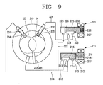
- FIGS 7, 8 and 9 are sectional views for explaining the operation in accordance with the second embodiment of the present invention.
- the compression units 10 and 20 operate, separately, to thereby discharge 100% of refrigerant flux.
- the electromagnet 217 of the second pressure switching unit 211 a pilot valve
- the second switching valve 216 overcomes the switching spring 218 to allow communication between the high pressure inlet 212 and the common outlet 214.
- discharge pressure applied to one side of the second sliding valve 231 gets higher than the internal pressure applied to the other side of the second sliding valve 231, of each cylinder 11 and 21, thereby moving forward the second sliding valve 231 and blocking the second bypass hole 234.
- the third sliding valve 232 moves forward to block the third bypass hole 235.
- the refrigerant gas sucked to the first cylinder 11 and the refrigerant gas sucked to the second cylinder 21 are not mixed but completely compressed and discharged into the casing 1, alternately.
- a multi-stage rotary compressor operates in a saving mode.
- the second switching valve 216 overcomes the switching spring 218 to allow communication between the high pressure inlet 212 and the common outlet 214.
- the discharge pressure applied to one side of the second sliding valve 231 gets higher than the internal pressure of each cylinder 11 and 21, which is applied to the other side of the second sliding valve 231, thereby moving forward the second sliding valve 231 and blocking the second bypass hole 234.
- the low pressure inlet 223 communicates with the common outlet 224.
- the low pressure inlet 233 is connected to the third low pressure connection pipe and the connection pipe, low pressure refrigerants are flowing therein.
- Such refrigerants are supplied to the back of the third sliding valve 232 through the communication hole.
- the third sliding valve 232 moves backward by the compression force of the valve spring, thereby opening the third bypass hole 235 and allowing communication between compression chambers of inner spaces of the cylinders.
- the refrigerant is moved from the high pressure compression chamber to the low one through the third bypass hole 235 such that the refrigerant cannot be compressed.
- the refrigerants are no longer bypassed but are compressed and discharged.
- the refrigerants cannot be compressed as much as an entire volume of each compression chamber and are bypassed from the high pressure compression chamber to the low pressure compression chamber. Thus, only some of the refrigerants are compressed and discharged. Such processes are repeated, thereby decreasing a discharge capacity of a refrigerant.
- the second bypass hole 234 is opened and the third bypass hole 235 is closed by manipulating the second and third pressure switching unit 211 and 221.
- the second bypass hole 234 is more adjacent to the vane 410, 420 than the third bypass hole 235 along a rotating direction of the rotary shaft 14 (e.g., the second bypass hole 160 degrees, third bypass hole 240 degrees). Accordingly, the amount of refrigerants compressed and discharged as the rolling piston or the eccentric portion closes the second bypass hole 234 is greater than that of refrigerants discharged as the third bypass hole 235 is closed. Accordingly, the amount of discharged refrigerants can be changed even in the saving mode.
- multi-stage capacity changes can be implemented by forming three or more bypass holes at a middle bearing.
- the multi-stage rotary compressor in accordance with the present invention has the following effect.
- the present invention is advantageous in that a special part and a mounting space are not necessary and a manufacturing process is simple. Also, because a piece for the moving back and fixing of the vane is not needed, problems such as abrasion, foreign substance generation and the like are not generated, thereby improving reliability.
Landscapes
- Engineering & Computer Science (AREA)
- Mechanical Engineering (AREA)
- General Engineering & Computer Science (AREA)
- Applications Or Details Of Rotary Compressors (AREA)
Applications Claiming Priority (2)
| Application Number | Priority Date | Filing Date | Title |
|---|---|---|---|
| KR20040088013 | 2004-11-01 | ||
| KR1020050004710A KR100619767B1 (ko) | 2004-11-01 | 2005-01-18 | 다단 로터리 압축기의 용량가변장치 |
Publications (2)
| Publication Number | Publication Date |
|---|---|
| EP1653085A1 true EP1653085A1 (fr) | 2006-05-03 |
| EP1653085B1 EP1653085B1 (fr) | 2009-04-15 |
Family
ID=35788344
Family Applications (1)
| Application Number | Title | Priority Date | Filing Date |
|---|---|---|---|
| EP05012405A Expired - Lifetime EP1653085B1 (fr) | 2004-11-01 | 2005-06-09 | Compresseur rotatif multi-étagé à capacité variable |
Country Status (2)
| Country | Link |
|---|---|
| US (1) | US7665973B2 (fr) |
| EP (1) | EP1653085B1 (fr) |
Families Citing this family (19)
| Publication number | Priority date | Publication date | Assignee | Title |
|---|---|---|---|---|
| ITTO20050839A1 (it) * | 2005-11-28 | 2007-05-29 | Faiveley Transp Piossasco S P A | Gruppo di generazione e trattamento di fluidi aeriformi compressi, con sistema di raffreddamento perfezionato. |
| KR101316247B1 (ko) * | 2007-07-31 | 2013-10-08 | 엘지전자 주식회사 | 로터리 식 2단 압축기 |
| KR101442545B1 (ko) * | 2008-07-22 | 2014-09-22 | 엘지전자 주식회사 | 용량 가변형 로터리 압축기 |
| CN102124229B (zh) * | 2008-08-05 | 2014-03-26 | Lg电子株式会社 | 旋转式压缩机 |
| JP5515990B2 (ja) * | 2010-04-06 | 2014-06-11 | 株式会社Ihi | ターボ圧縮機及びターボ冷凍機 |
| US9267504B2 (en) | 2010-08-30 | 2016-02-23 | Hicor Technologies, Inc. | Compressor with liquid injection cooling |
| EP2612035A2 (fr) | 2010-08-30 | 2013-07-10 | Oscomp Systems Inc. | Compresseur à refroidissement par injection de liquide |
| US9546659B2 (en) * | 2011-03-10 | 2017-01-17 | Panasonic Intellectual Property Management Co., Ltd. | Rotary compressor |
| JP5914975B2 (ja) * | 2011-03-29 | 2016-05-11 | 株式会社富士通ゼネラル | ロータリ圧縮機の製造方法 |
| WO2015122991A2 (fr) | 2014-02-17 | 2015-08-20 | Carrier Corporation | Dérivation de gaz chauds pour compresseur à deux étages |
| WO2016076064A1 (fr) * | 2014-11-10 | 2016-05-19 | 東芝キヤリア株式会社 | Compresseur rotatif et dispositif de cycle de réfrigération |
| CN106704189A (zh) * | 2015-08-10 | 2017-05-24 | 珠海格力节能环保制冷技术研究中心有限公司 | 压缩机和换热系统 |
| CN106168214A (zh) * | 2016-06-29 | 2016-11-30 | 珠海格力节能环保制冷技术研究中心有限公司 | 一种转缸增焓活塞压缩机及具有其的空调系统 |
| CN107842486B (zh) * | 2017-11-24 | 2024-01-26 | 安徽美芝精密制造有限公司 | 压缩机以及具有其的空调系统 |
| GB2572958C (en) * | 2018-04-16 | 2021-06-23 | Edwards Ltd | A multi-stage vacuum pump and a method of differentially pumping multiple vacuum chambers |
| CN108869287B (zh) * | 2018-07-10 | 2024-03-29 | 珠海凌达压缩机有限公司 | 变容压缩机构、压缩机及空调器 |
| JP7502638B2 (ja) | 2020-10-30 | 2024-06-19 | ダイキン工業株式会社 | ロータリ圧縮機 |
| JP7436727B1 (ja) | 2023-04-24 | 2024-02-22 | コベルコ・コンプレッサ株式会社 | 冷凍システム |
| CN119267231B (zh) * | 2024-12-09 | 2025-11-07 | 珠海格力电器股份有限公司 | 缸体、气缸、压缩机和空调器 |
Citations (5)
| Publication number | Priority date | Publication date | Assignee | Title |
|---|---|---|---|---|
| US4726739A (en) * | 1985-09-20 | 1988-02-23 | Sanyo Electric Co., Ltd. | Multiple cylinder rotary compressor |
| JPH0735071A (ja) * | 1993-07-22 | 1995-02-03 | Toshiba Corp | 多気筒形回転圧縮機 |
| JPH0754782A (ja) * | 1993-08-12 | 1995-02-28 | Toshiba Corp | 多気筒形回転圧縮機 |
| EP1312880A2 (fr) * | 2001-11-19 | 2003-05-21 | Sanyo Electric Co., Ltd. | Compresseur rotatif et circuit frigorifique |
| US6796773B1 (en) * | 2003-05-21 | 2004-09-28 | Samsung Electronics Co., Ltd. | Variable capacity rotary compressor |
Family Cites Families (10)
| Publication number | Priority date | Publication date | Assignee | Title |
|---|---|---|---|---|
| US3002461A (en) * | 1956-08-13 | 1961-10-03 | Eaton Mfg Co | Variable capacity pump |
| US3552658A (en) * | 1969-06-03 | 1971-01-05 | W & W Steel Co | Spray valve assembly |
| US3727877A (en) * | 1970-03-04 | 1973-04-17 | Chayes Dental Inst Corp | Piloted shut-off valve |
| US3779537A (en) * | 1973-02-20 | 1973-12-18 | Napoleon Spring Works Inc | Cone apparatus |
| US4712778A (en) * | 1981-12-21 | 1987-12-15 | North American Philips Corporation | Helical spring holder assembly |
| US4905775A (en) * | 1988-09-15 | 1990-03-06 | Amoco Corporation | Drilling system and flow control apparatus for downhole drilling motors |
| JP2904572B2 (ja) * | 1990-10-31 | 1999-06-14 | 株式会社東芝 | 多気筒型回転圧縮機 |
| US5190076A (en) * | 1991-11-07 | 1993-03-02 | Kloehn Michael F | Low energy three way valve |
| JP3408005B2 (ja) * | 1995-01-30 | 2003-05-19 | 三洋電機株式会社 | 多気筒回転圧縮機 |
| DE102004022275A1 (de) * | 2004-05-06 | 2005-12-01 | Robert Bosch Gmbh | Druckregelventil |
-
2005
- 2005-06-01 US US11/140,906 patent/US7665973B2/en not_active Expired - Fee Related
- 2005-06-09 EP EP05012405A patent/EP1653085B1/fr not_active Expired - Lifetime
Patent Citations (5)
| Publication number | Priority date | Publication date | Assignee | Title |
|---|---|---|---|---|
| US4726739A (en) * | 1985-09-20 | 1988-02-23 | Sanyo Electric Co., Ltd. | Multiple cylinder rotary compressor |
| JPH0735071A (ja) * | 1993-07-22 | 1995-02-03 | Toshiba Corp | 多気筒形回転圧縮機 |
| JPH0754782A (ja) * | 1993-08-12 | 1995-02-28 | Toshiba Corp | 多気筒形回転圧縮機 |
| EP1312880A2 (fr) * | 2001-11-19 | 2003-05-21 | Sanyo Electric Co., Ltd. | Compresseur rotatif et circuit frigorifique |
| US6796773B1 (en) * | 2003-05-21 | 2004-09-28 | Samsung Electronics Co., Ltd. | Variable capacity rotary compressor |
Non-Patent Citations (1)
| Title |
|---|
| PATENT ABSTRACTS OF JAPAN vol. 1995, no. 05 30 June 1995 (1995-06-30) * |
Also Published As
| Publication number | Publication date |
|---|---|
| US7665973B2 (en) | 2010-02-23 |
| US20060090488A1 (en) | 2006-05-04 |
| EP1653085B1 (fr) | 2009-04-15 |
Similar Documents
| Publication | Publication Date | Title |
|---|---|---|
| EP1653085B1 (fr) | Compresseur rotatif multi-étagé à capacité variable | |
| CN1249353C (zh) | 可变容量的旋转式压缩机 | |
| CN100585186C (zh) | 变容型旋转压缩机 | |
| JP6291533B2 (ja) | 高圧圧縮機及びそれを備えた冷凍サイクル装置 | |
| US20080193310A1 (en) | Capacity Varying Type Rotary Compressor and Refrigeration System Having the Same | |
| US7931453B2 (en) | Capacity variable device for rotary compressor and driving method of air conditioner having the same | |
| US7988431B2 (en) | Capacity-variable rotary compressor | |
| US7611341B2 (en) | Capacity varying type rotary compressor | |
| CN100540906C (zh) | 可变容量回转式压缩机及其驱动方法 | |
| WO2008023962A1 (fr) | Compresseur rotatif du type à capacité variable | |
| CN100400883C (zh) | 用于改变多级旋转式压缩机容量的装置 | |
| CN1307394C (zh) | 一种压缩-膨胀机的制备方法 | |
| KR100620044B1 (ko) | 로터리 압축기의 용량 가변 장치 | |
| KR100724452B1 (ko) | 용량 가변형 로터리 압축기 | |
| KR100677522B1 (ko) | 로터리 압축기의 용량 가변 장치 | |
| KR100585807B1 (ko) | 용량 가변형 복식 로터리 압축기 및 그 운전 방법 | |
| KR101194608B1 (ko) | 용량 가변형 로터리 압축기 | |
| KR101002555B1 (ko) | 다단 로터리 압축기 및 이를 적용한 냉동사이클 장치 | |
| KR100585808B1 (ko) | 다단 로터리 압축기 | |
| KR100677516B1 (ko) | 다단 로터리 압축기 | |
| KR100677527B1 (ko) | 로터리 압축기 | |
| KR100724451B1 (ko) | 용량 가변형 로터리 압축기 | |
| KR100620030B1 (ko) | 용량 가변 압축기 | |
| KR100873682B1 (ko) | 다단 로터리 압축기 | |
| KR100620033B1 (ko) | 용량 가변형 로터리 압축기 및 이를 적용한 공조기 |
Legal Events
| Date | Code | Title | Description |
|---|---|---|---|
| PUAI | Public reference made under article 153(3) epc to a published international application that has entered the european phase |
Free format text: ORIGINAL CODE: 0009012 |
|
| AK | Designated contracting states |
Kind code of ref document: A1 Designated state(s): AT BE BG CH CY CZ DE DK EE ES FI FR GB GR HU IE IS IT LI LT LU MC NL PL PT RO SE SI SK TR |
|
| AX | Request for extension of the european patent |
Extension state: AL BA HR LV MK YU |
|
| 17P | Request for examination filed |
Effective date: 20060601 |
|
| AKX | Designation fees paid |
Designated state(s): DE FR GB IT |
|
| 17Q | First examination report despatched |
Effective date: 20071126 |
|
| GRAP | Despatch of communication of intention to grant a patent |
Free format text: ORIGINAL CODE: EPIDOSNIGR1 |
|
| GRAS | Grant fee paid |
Free format text: ORIGINAL CODE: EPIDOSNIGR3 |
|
| GRAA | (expected) grant |
Free format text: ORIGINAL CODE: 0009210 |
|
| AK | Designated contracting states |
Kind code of ref document: B1 Designated state(s): DE FR GB IT |
|
| REG | Reference to a national code |
Ref country code: GB Ref legal event code: FG4D |
|
| REF | Corresponds to: |
Ref document number: 602005013883 Country of ref document: DE Date of ref document: 20090528 Kind code of ref document: P |
|
| PLBE | No opposition filed within time limit |
Free format text: ORIGINAL CODE: 0009261 |
|
| STAA | Information on the status of an ep patent application or granted ep patent |
Free format text: STATUS: NO OPPOSITION FILED WITHIN TIME LIMIT |
|
| 26N | No opposition filed |
Effective date: 20100118 |
|
| PGFP | Annual fee paid to national office [announced via postgrant information from national office to epo] |
Ref country code: IT Payment date: 20110321 Year of fee payment: 7 Ref country code: FR Payment date: 20110401 Year of fee payment: 7 |
|
| PGFP | Annual fee paid to national office [announced via postgrant information from national office to epo] |
Ref country code: GB Payment date: 20110401 Year of fee payment: 7 |
|
| GBPC | Gb: european patent ceased through non-payment of renewal fee |
Effective date: 20120609 |
|
| PG25 | Lapsed in a contracting state [announced via postgrant information from national office to epo] |
Ref country code: IT Free format text: LAPSE BECAUSE OF NON-PAYMENT OF DUE FEES Effective date: 20120609 |
|
| REG | Reference to a national code |
Ref country code: FR Ref legal event code: ST Effective date: 20130228 |
|
| REG | Reference to a national code |
Ref country code: DE Ref legal event code: R119 Ref document number: 602005013883 Country of ref document: DE Effective date: 20130101 |
|
| PG25 | Lapsed in a contracting state [announced via postgrant information from national office to epo] |
Ref country code: DE Free format text: LAPSE BECAUSE OF NON-PAYMENT OF DUE FEES Effective date: 20130101 Ref country code: GB Free format text: LAPSE BECAUSE OF NON-PAYMENT OF DUE FEES Effective date: 20120609 Ref country code: FR Free format text: LAPSE BECAUSE OF NON-PAYMENT OF DUE FEES Effective date: 20120702 |
|
| PGFP | Annual fee paid to national office [announced via postgrant information from national office to epo] |
Ref country code: DE Payment date: 20110328 Year of fee payment: 7 |