EP1653111A1 - Elektromechanischer Aktuator für eine Fahrzeugbremse, Bremse mit einem solchen Aktuator sowie Verfahren zur Wartung der Bremse - Google Patents
Elektromechanischer Aktuator für eine Fahrzeugbremse, Bremse mit einem solchen Aktuator sowie Verfahren zur Wartung der Bremse Download PDFInfo
- Publication number
- EP1653111A1 EP1653111A1 EP05292123A EP05292123A EP1653111A1 EP 1653111 A1 EP1653111 A1 EP 1653111A1 EP 05292123 A EP05292123 A EP 05292123A EP 05292123 A EP05292123 A EP 05292123A EP 1653111 A1 EP1653111 A1 EP 1653111A1
- Authority
- EP
- European Patent Office
- Prior art keywords
- actuator
- brake
- support
- screw
- nut
- Prior art date
- Legal status (The legal status is an assumption and is not a legal conclusion. Google has not performed a legal analysis and makes no representation as to the accuracy of the status listed.)
- Granted
Links
- 238000000034 method Methods 0.000 title claims abstract description 7
- 238000012423 maintenance Methods 0.000 title abstract description 5
- 230000005662 electromechanics Effects 0.000 title 1
- 238000001514 detection method Methods 0.000 description 1
- 230000001627 detrimental effect Effects 0.000 description 1
- 238000006073 displacement reaction Methods 0.000 description 1
Images

Classifications
-
- F—MECHANICAL ENGINEERING; LIGHTING; HEATING; WEAPONS; BLASTING
- F16—ENGINEERING ELEMENTS AND UNITS; GENERAL MEASURES FOR PRODUCING AND MAINTAINING EFFECTIVE FUNCTIONING OF MACHINES OR INSTALLATIONS; THERMAL INSULATION IN GENERAL
- F16D—COUPLINGS FOR TRANSMITTING ROTATION; CLUTCHES; BRAKES
- F16D65/00—Parts or details
- F16D65/14—Actuating mechanisms for brakes; Means for initiating operation at a predetermined position
- F16D65/16—Actuating mechanisms for brakes; Means for initiating operation at a predetermined position arranged in or on the brake
- F16D65/18—Actuating mechanisms for brakes; Means for initiating operation at a predetermined position arranged in or on the brake adapted for drawing members together, e.g. for disc brakes
-
- F—MECHANICAL ENGINEERING; LIGHTING; HEATING; WEAPONS; BLASTING
- F16—ENGINEERING ELEMENTS AND UNITS; GENERAL MEASURES FOR PRODUCING AND MAINTAINING EFFECTIVE FUNCTIONING OF MACHINES OR INSTALLATIONS; THERMAL INSULATION IN GENERAL
- F16D—COUPLINGS FOR TRANSMITTING ROTATION; CLUTCHES; BRAKES
- F16D65/00—Parts or details
- F16D65/0043—Brake maintenance and assembly, tools therefor
-
- F—MECHANICAL ENGINEERING; LIGHTING; HEATING; WEAPONS; BLASTING
- F16—ENGINEERING ELEMENTS AND UNITS; GENERAL MEASURES FOR PRODUCING AND MAINTAINING EFFECTIVE FUNCTIONING OF MACHINES OR INSTALLATIONS; THERMAL INSULATION IN GENERAL
- F16D—COUPLINGS FOR TRANSMITTING ROTATION; CLUTCHES; BRAKES
- F16D2121/00—Type of actuator operation force
- F16D2121/18—Electric or magnetic
- F16D2121/24—Electric or magnetic using motors
-
- F—MECHANICAL ENGINEERING; LIGHTING; HEATING; WEAPONS; BLASTING
- F16—ENGINEERING ELEMENTS AND UNITS; GENERAL MEASURES FOR PRODUCING AND MAINTAINING EFFECTIVE FUNCTIONING OF MACHINES OR INSTALLATIONS; THERMAL INSULATION IN GENERAL
- F16D—COUPLINGS FOR TRANSMITTING ROTATION; CLUTCHES; BRAKES
- F16D2125/00—Components of actuators
- F16D2125/18—Mechanical mechanisms
- F16D2125/20—Mechanical mechanisms converting rotation to linear movement or vice versa
- F16D2125/34—Mechanical mechanisms converting rotation to linear movement or vice versa acting in the direction of the axis of rotation
- F16D2125/40—Screw-and-nut
Definitions
- the invention relates to an electromechanical actuator for a vehicle brake, a vehicle brake comprising such an actuator, and a method of maintenance of such an actuator.
- Such a maintenance method can however pose a number of problems, among which the difficulty of re-positioning the actuator on the brake, especially if the actuator is in an inaccessible region of the brake.
- the subject of the invention is an actuator which does not have the drawbacks of the prior art.
- the part of the actuator most likely to fail is that which comprises the electric motor.
- the subdivision of the actuator according to the invention makes it possible to replace only the second part in case of failure of the engine alone, thus avoiding disassembly of the first part which remains in place on the brake, which eliminates the problems of repositioning the engine. actuation (at least here of the screw-nut system) on the brake facing the friction elements.
- the invention also relates to a vehicle brake comprising friction elements and a support extending facing the friction elements to carry at least one actuator according to the invention, the brake being arranged so that the second part of the actuator can be separated from the first part of the actuator while the latter is still carried by the support.
- the brake support is arranged to make it impossible to dismantle the first part of the actuator of the support if the second part of the actuator has not been separated from the first part of the actuator.
- the support is arranged to receive the first part of the actuator in a first mounting path, and to receive the second part of the actuator according to a second mounting path distinct from the first trajectory of the actuator. mounting.
- the first mounting path extends in a plane perpendicular to a longitudinal axis of the brake, and the second mounting path extends in a direction parallel to said longitudinal axis of the brake.
- FIG. 1 an aircraft wheel 1 mounted for rotation on an axle 2 along a longitudinal axis X.
- the wheel 1 is associated with a brake 3 extending generally along the axis X, comprising a stack of disks 5 (comprising stators disks alternated with rotor disks), and a support 4 attached to the axle 2 which carries a number of electromechanical actuators 6.
- the support 4 comprises a tubular portion 4.1 cooperating with some of the disks of the stack of disks 5, and a plate 4.2 receiving the actuators 6.
- the plate 4.2 has a bore 7 receiving a toc (not shown) rotational stop of the support 4 of the brake 3.
- each actuator 6 comprises a first part 10 which receives a nut 11 rotating about an axis Y.
- the nut 11 cooperates with a screw 12 terminated by a shoe 13.
- An antirotation member 14 externally splined extends along the Y axis to cooperate with the screw 12 to prevent it from rotating.
- the nut comprises a gear 15 which, via a number of reduction stages 16, is connected in rotation to an input gear 17.
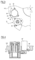
- the actuator 6 has a second portion 20 attached to the plate 4.2.
- the second part 20 houses an electric motor 21 which is seen here the shaft 21 protrude.
- the shaft of the electric motor 21 enters the first part 10 to cooperate with the input gear 17 and allow the drive of the nut 11 by the electric motor 21, and hence the displacement of the screw 12 facing the stack of disks 5.
- the actuators 6 thus make it possible to impose on the pile of disks 5 a pressure force via the pad 13 which generates a friction slowing down the rotation of the wheel 1.
- the two parts are thus very easily separable, and constitute two units replaceable online (LRU in English) independently of one another.
- the plate 4.2 of the support 4 defines forks 30 (one is visible here) having openings directed in perpendicular directions. to the X axis indicated by the arrows 31.
- each of the forks 30 is accommodated the first portion 10 of an actuator 6, so that the Y axis which extends the screw-nut system 11,12 of the actuator is parallel to the longitudinal axis X ( seen here at the end) of the brake.
- an orifice 40 of the plate 4.2 formed next to each fork 30 extends the second portion 20 associated with the actuator 6.
- a power supply cable 32 extends from the second part 20 to a not shown feed plate of the support 4.
- the second part 20 is removable from the plate 4.2 without it being necessary for this to separate the first part 10 of the plate 4.2.
- This aspect of the invention is particularly useful to intervene following the detection of a failure of one of the actuators. Indeed, if the engine is the faulty member of the actuator, then simply replace the second part 20, without touching the first part 10 of the actuator concerned.
- the two parts are thus very easily separable, and constitute two units replaceable online (LRU in English) independently of one another.
- the first part 20 of the actuator of the plate 4.2 is separated by moving it away in a direction parallel to the axis X, then the first part of the support is removed by moving it away according to a direction 31 perpendicular to the X axis.
- the first part 10 of an actuator is reported on the plate 4.2 in a direction 31 perpendicular to the axis X, then the second part 20 is reported on the plate 4.2 in a direction parallel to the X axis.
- the actuator of the invention it will be possible to design the actuator of the invention so that the second part 20 'is attached directly to the first part 10' and no longer to the plate 4.2. As above, the first part 10 'can not be dismounted from the support 4.2 if the second part 20' has not been previously dismounted.
- the first part of the actuator is removable from the brake support
- the first part may be integrated into the brake support so as not to be dismountable in use.
- the trajectories mounting may be arbitrary.
- the nut of the actuator is rotated for the motor, it can be expected that the motor drives the screw in rotation.
- the actuator on the brake of the invention may not have this characteristic, of so that it is possible to remove the first part while the second part is still secured to the support, or to disassemble the actuator in block, the two parts remaining however separable between them when the actuator is mounted on the brake.
Landscapes
- Engineering & Computer Science (AREA)
- General Engineering & Computer Science (AREA)
- Mechanical Engineering (AREA)
- Braking Arrangements (AREA)
- Braking Systems And Boosters (AREA)
Applications Claiming Priority (1)
| Application Number | Priority Date | Filing Date | Title |
|---|---|---|---|
| FR0411509A FR2877411B1 (fr) | 2004-10-28 | 2004-10-28 | Actionneur electromecanique pour frein de vehicule, frein comportant un tel actionneur et procede de maintenance d'un tel frein |
Publications (2)
| Publication Number | Publication Date |
|---|---|
| EP1653111A1 true EP1653111A1 (de) | 2006-05-03 |
| EP1653111B1 EP1653111B1 (de) | 2014-04-30 |
Family
ID=34952827
Family Applications (1)
| Application Number | Title | Priority Date | Filing Date |
|---|---|---|---|
| EP05292123.6A Expired - Lifetime EP1653111B1 (de) | 2004-10-28 | 2005-10-12 | Fahrzeugbremse mit elektromechanischem Aktuator |
Country Status (4)
| Country | Link |
|---|---|
| US (2) | US7395905B2 (de) |
| EP (1) | EP1653111B1 (de) |
| CA (1) | CA2525073C (de) |
| FR (1) | FR2877411B1 (de) |
Cited By (2)
| Publication number | Priority date | Publication date | Assignee | Title |
|---|---|---|---|---|
| EP2000692A1 (de) * | 2007-06-05 | 2008-12-10 | Messier-Bugatti | An eine konische Achse angepasste Bremse |
| FR3013294A1 (fr) * | 2013-11-20 | 2015-05-22 | Messier Bugatti Dowty | Actionneur electromecanique pour frein de vehicule et systeme de freinage comportant un tel actionneur. |
Families Citing this family (5)
| Publication number | Priority date | Publication date | Assignee | Title |
|---|---|---|---|---|
| US8919504B2 (en) * | 2009-12-03 | 2014-12-30 | Honeywell International Inc. | Brake actuator assembly with line replaceable motor features |
| US9815438B2 (en) | 2010-02-12 | 2017-11-14 | Honeywell International Inc. | Aircraft electric brake actuator assembly with line replaceable actuator brake |
| FR3018880B1 (fr) | 2014-03-24 | 2017-08-25 | Messier Bugatti Dowty | Actionneur electromecanique de frein a blocage de parc pour aeronef |
| JP6352202B2 (ja) * | 2015-02-16 | 2018-07-04 | 株式会社ミツバ | ブレーキ用アクチュエータおよびブレーキ装置 |
| US11518353B2 (en) * | 2020-06-17 | 2022-12-06 | The Boeing Company | Systems and method for determining running clearance brake command for a brake system |
Citations (2)
| Publication number | Priority date | Publication date | Assignee | Title |
|---|---|---|---|---|
| US6095293A (en) | 1998-02-13 | 2000-08-01 | The B. F. Goodrich Company | Aircraft brake and method with electromechanical actuator modules |
| WO2001020188A1 (en) * | 1999-09-13 | 2001-03-22 | The B.F.Goodrich Company | Electric brake actuator module for aircraft |
Family Cites Families (4)
| Publication number | Priority date | Publication date | Assignee | Title |
|---|---|---|---|---|
| EP0847508B1 (de) * | 1995-09-21 | 2003-03-05 | Lucas Industries Limited | Bremsaktor für elektrisch betätigbare fahrzeugbremse |
| NL1007296C2 (nl) * | 1997-10-16 | 1999-04-19 | Skf Ind Trading & Dev | Modulaire actuator, alsmede remklauw met een dergelijke actuator. |
| NL1009197C2 (nl) * | 1998-05-18 | 1999-11-19 | Skf Eng & Res Centre Bv | Schroefactuator, en remklauw met een dergelijke schroefactuator. |
| WO2001036837A1 (en) * | 1999-11-18 | 2001-05-25 | Skf Engineering And Research Centre B.V. | Actuator having a central support, and brake calliper comprising such actuator |
-
2004
- 2004-10-28 FR FR0411509A patent/FR2877411B1/fr not_active Expired - Lifetime
- 2004-11-30 US US10/998,638 patent/US7395905B2/en not_active Expired - Lifetime
-
2005
- 2005-10-12 EP EP05292123.6A patent/EP1653111B1/de not_active Expired - Lifetime
- 2005-10-25 CA CA2525073A patent/CA2525073C/fr not_active Expired - Fee Related
-
2008
- 2008-03-24 US US12/053,678 patent/US8317001B2/en not_active Expired - Lifetime
Patent Citations (3)
| Publication number | Priority date | Publication date | Assignee | Title |
|---|---|---|---|---|
| US6095293A (en) | 1998-02-13 | 2000-08-01 | The B. F. Goodrich Company | Aircraft brake and method with electromechanical actuator modules |
| US6662907B1 (en) * | 1998-02-13 | 2003-12-16 | The B. F. Goodrich Company | Aircraft brake and method with electromechanical actuator modules |
| WO2001020188A1 (en) * | 1999-09-13 | 2001-03-22 | The B.F.Goodrich Company | Electric brake actuator module for aircraft |
Cited By (6)
| Publication number | Priority date | Publication date | Assignee | Title |
|---|---|---|---|---|
| EP2000692A1 (de) * | 2007-06-05 | 2008-12-10 | Messier-Bugatti | An eine konische Achse angepasste Bremse |
| FR2917064A1 (fr) * | 2007-06-05 | 2008-12-12 | Messier Bugatti Sa | Frein adapte a un essieu conique |
| US7866448B2 (en) | 2007-06-05 | 2011-01-11 | Messier-Bugatti | Aircraft brake particularly adapted for mounting on a conical axle |
| FR3013294A1 (fr) * | 2013-11-20 | 2015-05-22 | Messier Bugatti Dowty | Actionneur electromecanique pour frein de vehicule et systeme de freinage comportant un tel actionneur. |
| EP2876008A1 (de) * | 2013-11-20 | 2015-05-27 | Messier-Bugatti-Dowty | Elektromechanisches Stellglied für Fahrzeugbremse und Bremssystem, das ein solches Stellglied umfasst. |
| US9638278B2 (en) | 2013-11-20 | 2017-05-02 | Messier-Bugarri-Dowty | Electromechanical actuator for vehicle brake and braking system comprising such an actuator |
Also Published As
| Publication number | Publication date |
|---|---|
| FR2877411B1 (fr) | 2007-02-09 |
| CA2525073A1 (fr) | 2006-04-28 |
| US20080169160A1 (en) | 2008-07-17 |
| US8317001B2 (en) | 2012-11-27 |
| FR2877411A1 (fr) | 2006-05-05 |
| US20060090970A1 (en) | 2006-05-04 |
| CA2525073C (fr) | 2011-04-12 |
| US7395905B2 (en) | 2008-07-08 |
| EP1653111B1 (de) | 2014-04-30 |
Similar Documents
| Publication | Publication Date | Title |
|---|---|---|
| EP2361830A1 (de) | Landefahrwerk mit Vorrichtung zum Antrieb vom Fahrwerksrad | |
| EP1653111A1 (de) | Elektromechanischer Aktuator für eine Fahrzeugbremse, Bremse mit einem solchen Aktuator sowie Verfahren zur Wartung der Bremse | |
| FR2898394A1 (fr) | Frein a disque de vehicule integrant un frein de stationnement. | |
| EP1584784A1 (de) | Einrichtung zur Montage von ringförmigen Flanschen, insbesondere in Turbomaschinen | |
| FR3091517A1 (fr) | Dispositif d’assistance électrique pour vélo | |
| CA2649112C (fr) | Atterrisseur, frein pour roue d'aeronef, ensemble de roue freinee d'aeronef, et procede de maintenance d'un tel atterrisseur | |
| EP2746611A1 (de) | Rad eines Luftfahrzeugs, das mit Stegbolzen ausgestattet ist | |
| EP2944521A1 (de) | Elektromechanisches Stellglied für Bremse mit Parksperre für Luftfahrzeug | |
| EP1352181A1 (de) | Elektromechanische betätigungseinrichtung einer mehrscheibenbremse für transportmittel, insbesondere für flugzeuge | |
| EP3701163A1 (de) | Gestufte drehmomentbremsvorrichtung | |
| EP1510719B1 (de) | Flugzeugbremseinheit | |
| EP0366509A1 (de) | Bremse mit zwei Scheiben mit festem Abstand | |
| EP1715564B1 (de) | Bremsvorrichtung für die Drehwelle eines Antriebs, wie ein Elektromotor | |
| WO2007063222A1 (fr) | Actionneur electromagnetique avec deux electroaimants comportant des aimants de forces differentes, et procede de gestion d'une soupape de moteur a combustion interne faisant application. | |
| EP2314488A1 (de) | Bremssystem mit einem Hauptbremszylinder | |
| EP1793139B1 (de) | Elektromechanische Bremse mit winkelverstellbaren Aktuatoren | |
| FR2809080A1 (fr) | Dispositif d'actionnement, notamment pour commande de vol d'aeronef | |
| EP1028263B1 (de) | Kupplung für Pumpe und Motor | |
| FR2732087A1 (fr) | Perfectionnements aux differentiels autobloquants | |
| EP3230613A1 (de) | Bremssattel in zwei teilen, scheibenbremse aus zwei materialien mit einer elektrohydraulischen feststellbremse und verfahren zur industrialisierung und anordnung | |
| EP4162157B1 (de) | Hydraulische maschine einschliesslich stützlager für den rotierenden abschnitt | |
| EP4253786B1 (de) | Elektromagnetische bremsvorrichtung, konfiguriert zum blockieren einer rotierenden welle, und mobilitätssystem, das die vorrichtung und die drehwelle besteht | |
| FR3133895A1 (fr) | Dispositif de freinage électromagnétique configuré pour bloquer un arbre rotatif et système de mobilité comportant le dispositif et l’arbre rotatif | |
| WO2025141269A1 (fr) | Assemblage pour turbomachine d'aeronef, comprenant un dispositif de secours de couplage mecanique de deux pieces tournantes de l'assemblage | |
| FR2849127A1 (fr) | Mecanisme d'embrayage equipe d'un dispositif d'entrainement d'un arbre dit de prise de force |
Legal Events
| Date | Code | Title | Description |
|---|---|---|---|
| PUAI | Public reference made under article 153(3) epc to a published international application that has entered the european phase |
Free format text: ORIGINAL CODE: 0009012 |
|
| AK | Designated contracting states |
Kind code of ref document: A1 Designated state(s): AT BE BG CH CY CZ DE DK EE ES FI FR GB GR HU IE IS IT LI LT LU LV MC NL PL PT RO SE SI SK TR |
|
| AX | Request for extension of the european patent |
Extension state: AL BA HR MK YU |
|
| 17P | Request for examination filed |
Effective date: 20061012 |
|
| 17Q | First examination report despatched |
Effective date: 20061121 |
|
| AKX | Designation fees paid |
Designated state(s): DE ES FR GB IT |
|
| RAP1 | Party data changed (applicant data changed or rights of an application transferred) |
Owner name: MESSIER-BUGATTI-DOWTY |
|
| GRAP | Despatch of communication of intention to grant a patent |
Free format text: ORIGINAL CODE: EPIDOSNIGR1 |
|
| INTG | Intention to grant announced |
Effective date: 20130703 |
|
| GRAS | Grant fee paid |
Free format text: ORIGINAL CODE: EPIDOSNIGR3 |
|
| GRAP | Despatch of communication of intention to grant a patent |
Free format text: ORIGINAL CODE: EPIDOSNIGR1 |
|
| INTG | Intention to grant announced |
Effective date: 20131203 |
|
| GRAA | (expected) grant |
Free format text: ORIGINAL CODE: 0009210 |
|
| AK | Designated contracting states |
Kind code of ref document: B1 Designated state(s): DE ES FR GB IT |
|
| REG | Reference to a national code |
Ref country code: GB Ref legal event code: FG4D Free format text: NOT ENGLISH |
|
| REG | Reference to a national code |
Ref country code: DE Ref legal event code: R096 Ref document number: 602005043428 Country of ref document: DE Effective date: 20140605 |
|
| PG25 | Lapsed in a contracting state [announced via postgrant information from national office to epo] |
Ref country code: ES Free format text: LAPSE BECAUSE OF FAILURE TO SUBMIT A TRANSLATION OF THE DESCRIPTION OR TO PAY THE FEE WITHIN THE PRESCRIBED TIME-LIMIT Effective date: 20140430 |
|
| REG | Reference to a national code |
Ref country code: DE Ref legal event code: R097 Ref document number: 602005043428 Country of ref document: DE |
|
| PLBE | No opposition filed within time limit |
Free format text: ORIGINAL CODE: 0009261 |
|
| STAA | Information on the status of an ep patent application or granted ep patent |
Free format text: STATUS: NO OPPOSITION FILED WITHIN TIME LIMIT |
|
| PG25 | Lapsed in a contracting state [announced via postgrant information from national office to epo] |
Ref country code: IT Free format text: LAPSE BECAUSE OF FAILURE TO SUBMIT A TRANSLATION OF THE DESCRIPTION OR TO PAY THE FEE WITHIN THE PRESCRIBED TIME-LIMIT Effective date: 20140430 |
|
| 26N | No opposition filed |
Effective date: 20150202 |
|
| REG | Reference to a national code |
Ref country code: DE Ref legal event code: R082 Ref document number: 602005043428 Country of ref document: DE Representative=s name: SCHAUMBURG & PARTNER PATENTANWAELTE GBR, DE Ref country code: DE Ref legal event code: R082 Ref document number: 602005043428 Country of ref document: DE Representative=s name: SCHAUMBURG & PARTNER PATENTANWAELTE MBB, DE Ref country code: DE Ref legal event code: R082 Ref document number: 602005043428 Country of ref document: DE Representative=s name: SCHAUMBURG UND PARTNER PATENTANWAELTE MBB, DE |
|
| REG | Reference to a national code |
Ref country code: DE Ref legal event code: R097 Ref document number: 602005043428 Country of ref document: DE Effective date: 20150202 |
|
| REG | Reference to a national code |
Ref country code: FR Ref legal event code: PLFP Year of fee payment: 12 |
|
| REG | Reference to a national code |
Ref country code: FR Ref legal event code: CD Owner name: MESSIER-BUGATTI-DOWTY, FR Effective date: 20170518 |
|
| REG | Reference to a national code |
Ref country code: FR Ref legal event code: PLFP Year of fee payment: 13 |
|
| REG | Reference to a national code |
Ref country code: FR Ref legal event code: PLFP Year of fee payment: 14 |
|
| PGFP | Annual fee paid to national office [announced via postgrant information from national office to epo] |
Ref country code: GB Payment date: 20210922 Year of fee payment: 17 |
|
| PGFP | Annual fee paid to national office [announced via postgrant information from national office to epo] |
Ref country code: DE Payment date: 20220616 Year of fee payment: 18 |
|
| GBPC | Gb: european patent ceased through non-payment of renewal fee |
Effective date: 20221012 |
|
| PG25 | Lapsed in a contracting state [announced via postgrant information from national office to epo] |
Ref country code: GB Free format text: LAPSE BECAUSE OF NON-PAYMENT OF DUE FEES Effective date: 20221012 |
|
| REG | Reference to a national code |
Ref country code: DE Ref legal event code: R119 Ref document number: 602005043428 Country of ref document: DE |
|
| PG25 | Lapsed in a contracting state [announced via postgrant information from national office to epo] |
Ref country code: DE Free format text: LAPSE BECAUSE OF NON-PAYMENT OF DUE FEES Effective date: 20240501 |
|
| PGFP | Annual fee paid to national office [announced via postgrant information from national office to epo] |
Ref country code: FR Payment date: 20240919 Year of fee payment: 20 |