EP1653211A1 - Rollenprüfstand für Kraftfahrzeuge - Google Patents
Rollenprüfstand für Kraftfahrzeuge Download PDFInfo
- Publication number
- EP1653211A1 EP1653211A1 EP04425817A EP04425817A EP1653211A1 EP 1653211 A1 EP1653211 A1 EP 1653211A1 EP 04425817 A EP04425817 A EP 04425817A EP 04425817 A EP04425817 A EP 04425817A EP 1653211 A1 EP1653211 A1 EP 1653211A1
- Authority
- EP
- European Patent Office
- Prior art keywords
- support roller
- test bench
- flexible element
- roller
- constituted
- Prior art date
- Legal status (The legal status is an assumption and is not a legal conclusion. Google has not performed a legal analysis and makes no representation as to the accuracy of the status listed.)
- Withdrawn
Links
- 230000005540 biological transmission Effects 0.000 claims abstract description 18
- 229910000831 Steel Inorganic materials 0.000 claims description 3
- 239000010959 steel Substances 0.000 claims description 3
- 238000009434 installation Methods 0.000 description 2
- 238000005299 abrasion Methods 0.000 description 1
- 238000009825 accumulation Methods 0.000 description 1
- YACLQRRMGMJLJV-UHFFFAOYSA-N chloroprene Chemical compound ClC(=C)C=C YACLQRRMGMJLJV-UHFFFAOYSA-N 0.000 description 1
- 239000011248 coating agent Substances 0.000 description 1
- 238000000576 coating method Methods 0.000 description 1
- 239000002360 explosive Substances 0.000 description 1
- 239000007789 gas Substances 0.000 description 1
- 239000000463 material Substances 0.000 description 1
- 229910001220 stainless steel Inorganic materials 0.000 description 1
- 239000010935 stainless steel Substances 0.000 description 1
- 231100000331 toxic Toxicity 0.000 description 1
- 230000002588 toxic effect Effects 0.000 description 1
- 238000004804 winding Methods 0.000 description 1
Images


Classifications
-
- G—PHYSICS
- G01—MEASURING; TESTING
- G01M—TESTING STATIC OR DYNAMIC BALANCE OF MACHINES OR STRUCTURES; TESTING OF STRUCTURES OR APPARATUS, NOT OTHERWISE PROVIDED FOR
- G01M17/00—Testing of vehicles
- G01M17/007—Wheeled or endless-tracked vehicles
- G01M17/0072—Wheeled or endless-tracked vehicles the wheels of the vehicle co-operating with rotatable rolls
- G01M17/0074—Details, e.g. roller construction, vehicle restraining devices
Definitions
- the present invention relates to a roller test bench for wheel vehicles such as motorcycles, motor vehicles, etc..
- Roller test benches normally used for tests of vehicles are constituted by one or more steel rollers rotating around a horizontal axis and connected to a brake.
- the diameter of the rollers varies from two to three times the diameter of tyre of the vehicle being tested.
- the tyre bears on a respective roller at an upper generatrix thereof.
- a smaller diameter of the roller causes excessive deformation of the tyre and does not allow to have a contact surface between tyre and roller such as to transmit all the power of the vehicle engine without rapidly damaging the tyre.
- the large diameter of the rollers implies the installation of the test bench in a pit with a depth of 3 to 4 meters, with consequent safety problems (possible accumulation of toxic or explosive gases) and high installation costs.
- the object of the present invention is to provide a roller test bench which allows to overcome the aforesaid drawbacks.
- said object is achieved by a roller test bench having the characteristics set out in the claims.
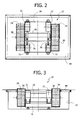
- the reference number 10 designates a roller test bench according to the present invention.
- the test bench 10 is housed in a pit 12, lowered relative to a horizontal plane 14 whereon can roll the wheels of a vehicle being tested.
- the test bench 10 comprises a stationary support structure 16 which bears on the bottom of the pit 12.
- the support structure 16 bears a brake 18 usually constituted by a rotating electrical machine controlled by an electronic apparatus capable of dosing and measuring the braking action.
- the brake 18 has an output shaft 19 ( Figure 1) whereon is keyed at least one support roller 20 whereon acts a respective wheel 22 of a vehicle undergoing testing.
- the roller test bench 10 is of the type used to test four wheel vehicles and it is therefore provided with two support rollers 20, mutually coaxial and fastened on respective end portions of the output shaft 19 at opposite parts relative to the brake 18. If the roller test bench 10 is used to test motor vehicles, it will be provided with a single support roller 20.
- the support roller 20 is mounted on an end portion of the output shaft 19.
- the diameter of the support roller 20 is limited to no more than 1.25 times the outer diameter of the tyre of the wheel 22 of the vehicle being tested.
- the roller test bench 10 comprises a flexible element closed in a loop 24 co-operating with the support roller 20.
- the flexible element 24 can be of various types, e.g.:
- the flexible element 24 co-operates with two transmission members and with the support roller 20.
- the transmission members are constituted by two idle pulleys 26, 28 rotatable around respective axes, parallel to the axis of rotation of the support roller 20.
- the transmission pulleys 26, 28 have lower diameter relative to the diameter of the support roller 20 and are arranged in such a way that the flexible element 24 has a planar upper segment 30 tangential to the support roller 20.
- the flexible element 24 has a lower segment wound on the support roller 20.
- the angle of winding of the flexible element 24 on the support roller 20 must be equal to or greater than about 15° to allow the transmission of power between the flexible element 24 and the support roller 20.
- the upper segment 30 of the flexible element 24 in use is positioned between the wheel 22 of the vehicle under test and the support roller 20.
- the two transmission pulleys 26, 28 are placed in such a position as to maintain nearly horizontal the upper segment 30 of the flexible element 24 before and after the region of contact with the tyre 22.
- a small adjustment in height of one or both transmission pulleys 26, 28 (in the order of 1-5 mm relative to the point of tangency) can be provided, which allows to reduce the deformation of the tyre of the wheel 22 in the region of contact with the upper segment 30 of the flexible element 22.
- the axes of rotation of the transmission pulleys 26, 28 are borne by respective uprights 31, 32.
- the upright 32 of the pulley 28 is fixed relative to the support structure 16 whilst the upright 31 of the pulley 26 is articulated to the support structure 16 around an axis 34 parallel to the axis of rotation of the pulley 26.
- the upright 31 is connected to a hydraulic or electromechanical actuator 36 which serves as a device for tensioning the flexible element 24.
- the actuator 36 allows to compensate the elongation of the flexible element 24 caused by the centrifugal force, which an be considerable at speeds exceeding 30 m/s.
- the pit 12 is closed superiorly by a roof 44 provided with openings through which projects the horizontal segment 30 of the flexible element 24.
- the transmission pulleys 26, 28 and the support roller 20 are mounted in overhang on the respective shafts 38, 40 and 19. This arrangement is advantages because, after loosening the tensioning device 36, the flexible element 24 can be removed and reinstalled without having to dismount the supports of the shafts bearing the transmission pulleys 26, 28 and the support roller 20.
- the support roller 20 and the transmission pulleys 26, 28 are provided with grooves with triangular profile.
- the support roller 20 is provided with a smooth central portion 42 whereon bear the ridges of the profiles of the belt 24, in order to reduce or eliminate the risk that the belt may be cut by the contact pressure exerted by the tyre of the wheel 22.
- the flexible element 24 is constituted by a toothed drive belt, the pulleys 26, 28 and the support roller 20 will be provided with corresponding teeth.
- the support roller 20 and the transmission pulleys 26, 28 will have flat surfaces.
- one of the pulleys 26, 28 can be provided with a motorised steering movement, controlled by an automatic adjustment system to contrast the lateral drift of the strip.
- roller test bench according to the invention can also be used to drive in rotation the wheels of a vehicle in aerodynamic tests in wind tunnels.
- the electric machine 18 is driving instead of braking.
- the solution according to the present invention allows to reduce the depth of the pit 12 because it allows to use support rollers 20 with reduced diameter.
- the flexible element 24 allows to obtain an extended contact area with the tyre 22 even with a support roller 20 with reduced diameter. Therefore the problems caused by the need to provide very deep pits are avoided, and also avoided are excessive stresses to the tyres, caused by the use of small rollers.
Landscapes
- Physics & Mathematics (AREA)
- General Physics & Mathematics (AREA)
- Testing Of Devices, Machine Parts, Or Other Structures Thereof (AREA)
Priority Applications (1)
| Application Number | Priority Date | Filing Date | Title |
|---|---|---|---|
| EP04425817A EP1653211A1 (de) | 2004-11-02 | 2004-11-02 | Rollenprüfstand für Kraftfahrzeuge |
Applications Claiming Priority (1)
| Application Number | Priority Date | Filing Date | Title |
|---|---|---|---|
| EP04425817A EP1653211A1 (de) | 2004-11-02 | 2004-11-02 | Rollenprüfstand für Kraftfahrzeuge |
Publications (1)
| Publication Number | Publication Date |
|---|---|
| EP1653211A1 true EP1653211A1 (de) | 2006-05-03 |
Family
ID=34932858
Family Applications (1)
| Application Number | Title | Priority Date | Filing Date |
|---|---|---|---|
| EP04425817A Withdrawn EP1653211A1 (de) | 2004-11-02 | 2004-11-02 | Rollenprüfstand für Kraftfahrzeuge |
Country Status (1)
| Country | Link |
|---|---|
| EP (1) | EP1653211A1 (de) |
Cited By (2)
| Publication number | Priority date | Publication date | Assignee | Title |
|---|---|---|---|---|
| JP2009109279A (ja) * | 2007-10-29 | 2009-05-21 | Toyo Eng Works Ltd | エンドレスベルト式走行試験装置 |
| CN103879724A (zh) * | 2012-12-19 | 2014-06-25 | 焦作市科瑞森机械制造有限公司 | 滚筒实验平台 |
Citations (3)
| Publication number | Priority date | Publication date | Assignee | Title |
|---|---|---|---|---|
| FR2707391A1 (fr) * | 1993-07-09 | 1995-01-13 | Ricard Claude | Dispositif de mesure pour taxi. |
| JPH09105707A (ja) * | 1995-10-11 | 1997-04-22 | Saginomiya Seisakusho Inc | ロードシミュレータにおけるフラットベルト装置 |
| DE10131069A1 (de) * | 2001-06-27 | 2003-01-09 | Sommer Tech Entwicklungen Gmbh | Flachbahn zum Test von Rad- und Fahrzeugsystemen mit Rädern |
-
2004
- 2004-11-02 EP EP04425817A patent/EP1653211A1/de not_active Withdrawn
Patent Citations (3)
| Publication number | Priority date | Publication date | Assignee | Title |
|---|---|---|---|---|
| FR2707391A1 (fr) * | 1993-07-09 | 1995-01-13 | Ricard Claude | Dispositif de mesure pour taxi. |
| JPH09105707A (ja) * | 1995-10-11 | 1997-04-22 | Saginomiya Seisakusho Inc | ロードシミュレータにおけるフラットベルト装置 |
| DE10131069A1 (de) * | 2001-06-27 | 2003-01-09 | Sommer Tech Entwicklungen Gmbh | Flachbahn zum Test von Rad- und Fahrzeugsystemen mit Rädern |
Non-Patent Citations (1)
| Title |
|---|
| PATENT ABSTRACTS OF JAPAN vol. 1997, no. 08 29 August 1997 (1997-08-29) * |
Cited By (3)
| Publication number | Priority date | Publication date | Assignee | Title |
|---|---|---|---|---|
| JP2009109279A (ja) * | 2007-10-29 | 2009-05-21 | Toyo Eng Works Ltd | エンドレスベルト式走行試験装置 |
| CN103879724A (zh) * | 2012-12-19 | 2014-06-25 | 焦作市科瑞森机械制造有限公司 | 滚筒实验平台 |
| CN103879724B (zh) * | 2012-12-19 | 2016-08-10 | 焦作科瑞森重装股份有限公司 | 滚筒实验平台 |
Similar Documents
| Publication | Publication Date | Title |
|---|---|---|
| EP2335041B1 (de) | Fahrzeugtestanordnung | |
| US7509846B2 (en) | Chassis dynamometer | |
| US6581448B2 (en) | Snug fitting apparatus for tire assembly and manufacturing method of tire assembly | |
| US7543487B2 (en) | Traveling test apparatus provided with flat-belt mechanism for vehicle | |
| US4886101A (en) | Wheel/tire load simulating apparatus | |
| US4944714A (en) | Method and apparatus for guidance and actuation of flat belt drive under external load | |
| CN118025494A (zh) | 一种飞机刹车试验装置 | |
| JP5117079B2 (ja) | 車両試験装置 | |
| CN117109942A (zh) | 一种叉车测试台 | |
| FI91057C (fi) | Käyttölaitesarja liikkuvalle käsijohteelle | |
| JP4726589B2 (ja) | シャシダイナモメータ | |
| JP4726590B2 (ja) | 走行試験装置 | |
| EP3290149B1 (de) | Seilrollenrändelwerkzeug und verfahren zum betrieb | |
| CN109731958A (zh) | 圈圆机及圈圆方法 | |
| US4569265A (en) | Slitter for steel belt | |
| CN210526755U (zh) | 一种无轮毂车轮 | |
| CN217305206U (zh) | 电动自行车测速装置 | |
| CN223100197U (zh) | 一种自动调速主动背压辊机构 | |
| JP2834158B2 (ja) | シヤシダイナモメータ | |
| CN220103909U (zh) | 制导舱支撑装置及制导舱检测装置 | |
| CN110907164A (zh) | 一种汽车传动轴外壳性能测试台 | |
| JP2004361213A (ja) | 車両試験装置 | |
| CN212639646U (zh) | 自动扶梯扶手带驱动能力测试装置 | |
| DE102004008091A1 (de) | Fahrzeugprüfstand | |
| JP4723223B2 (ja) | タイヤ搬送ローラコンベヤ |
Legal Events
| Date | Code | Title | Description |
|---|---|---|---|
| PUAI | Public reference made under article 153(3) epc to a published international application that has entered the european phase |
Free format text: ORIGINAL CODE: 0009012 |
|
| AK | Designated contracting states |
Kind code of ref document: A1 Designated state(s): AT BE BG CH CY CZ DE DK EE ES FI FR GB GR HU IE IS IT LI LU MC NL PL PT RO SE SI SK TR |
|
| AX | Request for extension of the european patent |
Extension state: AL HR LT LV MK YU |
|
| 17P | Request for examination filed |
Effective date: 20061016 |
|
| 17Q | First examination report despatched |
Effective date: 20061208 |
|
| AKX | Designation fees paid |
Designated state(s): AT BE BG CH CY CZ DE DK EE ES FI FR GB GR HU IE IS IT LI LU MC NL PL PT RO SE SI SK TR |
|
| 17Q | First examination report despatched |
Effective date: 20061208 |
|
| GRAP | Despatch of communication of intention to grant a patent |
Free format text: ORIGINAL CODE: EPIDOSNIGR1 |
|
| STAA | Information on the status of an ep patent application or granted ep patent |
Free format text: STATUS: THE APPLICATION IS DEEMED TO BE WITHDRAWN |
|
| 18D | Application deemed to be withdrawn |
Effective date: 20090603 |