EP1653216A2 - Dispositif microfluidique - Google Patents
Dispositif microfluidique Download PDFInfo
- Publication number
- EP1653216A2 EP1653216A2 EP05109921A EP05109921A EP1653216A2 EP 1653216 A2 EP1653216 A2 EP 1653216A2 EP 05109921 A EP05109921 A EP 05109921A EP 05109921 A EP05109921 A EP 05109921A EP 1653216 A2 EP1653216 A2 EP 1653216A2
- Authority
- EP
- European Patent Office
- Prior art keywords
- capillary
- fiber
- fluid channel
- optical fiber
- fluid
- Prior art date
- Legal status (The legal status is an assumption and is not a legal conclusion. Google has not performed a legal analysis and makes no representation as to the accuracy of the status listed.)
- Granted
Links
Images

Classifications
-
- G—PHYSICS
- G01—MEASURING; TESTING
- G01N—INVESTIGATING OR ANALYSING MATERIALS BY DETERMINING THEIR CHEMICAL OR PHYSICAL PROPERTIES
- G01N21/00—Investigating or analysing materials by the use of optical means, i.e. using sub-millimetre waves, infrared, visible or ultraviolet light
- G01N21/01—Arrangements or apparatus for facilitating the optical investigation
- G01N21/03—Cuvette constructions
- G01N21/0303—Optical path conditioning in cuvettes, e.g. windows; adapted optical elements or systems; path modifying or adjustment
-
- G—PHYSICS
- G01—MEASURING; TESTING
- G01N—INVESTIGATING OR ANALYSING MATERIALS BY DETERMINING THEIR CHEMICAL OR PHYSICAL PROPERTIES
- G01N27/00—Investigating or analysing materials by the use of electric, electrochemical, or magnetic means
- G01N27/26—Investigating or analysing materials by the use of electric, electrochemical, or magnetic means by investigating electrochemical variables; by using electrolysis or electrophoresis
- G01N27/416—Systems
- G01N27/447—Systems using electrophoresis
- G01N27/44704—Details; Accessories
- G01N27/44717—Arrangements for investigating the separated zones, e.g. localising zones
- G01N27/44721—Arrangements for investigating the separated zones, e.g. localising zones by optical means
-
- B—PERFORMING OPERATIONS; TRANSPORTING
- B01—PHYSICAL OR CHEMICAL PROCESSES OR APPARATUS IN GENERAL
- B01L—CHEMICAL OR PHYSICAL LABORATORY APPARATUS FOR GENERAL USE
- B01L3/00—Containers or dishes for laboratory use, e.g. laboratory glassware; Droppers
- B01L3/50—Containers for the purpose of retaining a material to be analysed, e.g. test tubes
- B01L3/502—Containers for the purpose of retaining a material to be analysed, e.g. test tubes with fluid transport, e.g. in multi-compartment structures
- B01L3/5027—Containers for the purpose of retaining a material to be analysed, e.g. test tubes with fluid transport, e.g. in multi-compartment structures by integrated microfluidic structures, i.e. dimensions of channels and chambers are such that surface tension forces are important, e.g. lab-on-a-chip
- B01L3/502715—Containers for the purpose of retaining a material to be analysed, e.g. test tubes with fluid transport, e.g. in multi-compartment structures by integrated microfluidic structures, i.e. dimensions of channels and chambers are such that surface tension forces are important, e.g. lab-on-a-chip characterised by interfacing components, e.g. fluidic, electrical, optical or mechanical interfaces
-
- B—PERFORMING OPERATIONS; TRANSPORTING
- B01—PHYSICAL OR CHEMICAL PROCESSES OR APPARATUS IN GENERAL
- B01L—CHEMICAL OR PHYSICAL LABORATORY APPARATUS FOR GENERAL USE
- B01L3/00—Containers or dishes for laboratory use, e.g. laboratory glassware; Droppers
- B01L3/50—Containers for the purpose of retaining a material to be analysed, e.g. test tubes
- B01L3/502—Containers for the purpose of retaining a material to be analysed, e.g. test tubes with fluid transport, e.g. in multi-compartment structures
- B01L3/5027—Containers for the purpose of retaining a material to be analysed, e.g. test tubes with fluid transport, e.g. in multi-compartment structures by integrated microfluidic structures, i.e. dimensions of channels and chambers are such that surface tension forces are important, e.g. lab-on-a-chip
- B01L3/50273—Containers for the purpose of retaining a material to be analysed, e.g. test tubes with fluid transport, e.g. in multi-compartment structures by integrated microfluidic structures, i.e. dimensions of channels and chambers are such that surface tension forces are important, e.g. lab-on-a-chip characterised by the means or forces applied to move the fluids
-
- F—MECHANICAL ENGINEERING; LIGHTING; HEATING; WEAPONS; BLASTING
- F04—POSITIVE - DISPLACEMENT MACHINES FOR LIQUIDS; PUMPS FOR LIQUIDS OR ELASTIC FLUIDS
- F04B—POSITIVE-DISPLACEMENT MACHINES FOR LIQUIDS; PUMPS
- F04B19/00—Machines or pumps having pertinent characteristics not provided for in, or of interest apart from, groups F04B1/00 - F04B17/00
- F04B19/006—Micropumps
-
- F—MECHANICAL ENGINEERING; LIGHTING; HEATING; WEAPONS; BLASTING
- F04—POSITIVE - DISPLACEMENT MACHINES FOR LIQUIDS; PUMPS FOR LIQUIDS OR ELASTIC FLUIDS
- F04B—POSITIVE-DISPLACEMENT MACHINES FOR LIQUIDS; PUMPS
- F04B19/00—Machines or pumps having pertinent characteristics not provided for in, or of interest apart from, groups F04B1/00 - F04B17/00
- F04B19/20—Other positive-displacement pumps
- F04B19/24—Pumping by heat expansion of pumped fluid
-
- G—PHYSICS
- G01—MEASURING; TESTING
- G01N—INVESTIGATING OR ANALYSING MATERIALS BY DETERMINING THEIR CHEMICAL OR PHYSICAL PROPERTIES
- G01N21/00—Investigating or analysing materials by the use of optical means, i.e. using sub-millimetre waves, infrared, visible or ultraviolet light
- G01N21/01—Arrangements or apparatus for facilitating the optical investigation
- G01N21/03—Cuvette constructions
- G01N21/05—Flow-through cuvettes
-
- G—PHYSICS
- G02—OPTICS
- G02B—OPTICAL ELEMENTS, SYSTEMS OR APPARATUS
- G02B6/00—Light guides; Structural details of arrangements comprising light guides and other optical elements, e.g. couplings
- G02B6/02—Optical fibres with cladding with or without a coating
- G02B6/032—Optical fibres with cladding with or without a coating with non solid core or cladding
-
- G—PHYSICS
- G02—OPTICS
- G02B—OPTICAL ELEMENTS, SYSTEMS OR APPARATUS
- G02B6/00—Light guides; Structural details of arrangements comprising light guides and other optical elements, e.g. couplings
- G02B6/24—Coupling light guides
-
- B—PERFORMING OPERATIONS; TRANSPORTING
- B01—PHYSICAL OR CHEMICAL PROCESSES OR APPARATUS IN GENERAL
- B01L—CHEMICAL OR PHYSICAL LABORATORY APPARATUS FOR GENERAL USE
- B01L2300/00—Additional constructional details
- B01L2300/08—Geometry, shape and general structure
- B01L2300/0832—Geometry, shape and general structure cylindrical, tube shaped
- B01L2300/0838—Capillaries
-
- B—PERFORMING OPERATIONS; TRANSPORTING
- B01—PHYSICAL OR CHEMICAL PROCESSES OR APPARATUS IN GENERAL
- B01L—CHEMICAL OR PHYSICAL LABORATORY APPARATUS FOR GENERAL USE
- B01L2400/00—Moving or stopping fluids
- B01L2400/04—Moving fluids with specific forces or mechanical means
- B01L2400/0403—Moving fluids with specific forces or mechanical means specific forces
- B01L2400/0442—Moving fluids with specific forces or mechanical means specific forces thermal energy, e.g. vaporisation, bubble jet
-
- B—PERFORMING OPERATIONS; TRANSPORTING
- B01—PHYSICAL OR CHEMICAL PROCESSES OR APPARATUS IN GENERAL
- B01L—CHEMICAL OR PHYSICAL LABORATORY APPARATUS FOR GENERAL USE
- B01L2400/00—Moving or stopping fluids
- B01L2400/04—Moving fluids with specific forces or mechanical means
- B01L2400/0403—Moving fluids with specific forces or mechanical means specific forces
- B01L2400/0454—Moving fluids with specific forces or mechanical means specific forces radiation pressure, optical tweezers
-
- B—PERFORMING OPERATIONS; TRANSPORTING
- B01—PHYSICAL OR CHEMICAL PROCESSES OR APPARATUS IN GENERAL
- B01L—CHEMICAL OR PHYSICAL LABORATORY APPARATUS FOR GENERAL USE
- B01L2400/00—Moving or stopping fluids
- B01L2400/04—Moving fluids with specific forces or mechanical means
- B01L2400/0493—Specific techniques used
- B01L2400/0496—Travelling waves, e.g. in combination with electrical or acoustic forces
-
- B—PERFORMING OPERATIONS; TRANSPORTING
- B01—PHYSICAL OR CHEMICAL PROCESSES OR APPARATUS IN GENERAL
- B01L—CHEMICAL OR PHYSICAL LABORATORY APPARATUS FOR GENERAL USE
- B01L3/00—Containers or dishes for laboratory use, e.g. laboratory glassware; Droppers
- B01L3/50—Containers for the purpose of retaining a material to be analysed, e.g. test tubes
- B01L3/502—Containers for the purpose of retaining a material to be analysed, e.g. test tubes with fluid transport, e.g. in multi-compartment structures
- B01L3/5027—Containers for the purpose of retaining a material to be analysed, e.g. test tubes with fluid transport, e.g. in multi-compartment structures by integrated microfluidic structures, i.e. dimensions of channels and chambers are such that surface tension forces are important, e.g. lab-on-a-chip
- B01L3/502707—Containers for the purpose of retaining a material to be analysed, e.g. test tubes with fluid transport, e.g. in multi-compartment structures by integrated microfluidic structures, i.e. dimensions of channels and chambers are such that surface tension forces are important, e.g. lab-on-a-chip characterised by the manufacture of the container or its components
-
- G—PHYSICS
- G01—MEASURING; TESTING
- G01N—INVESTIGATING OR ANALYSING MATERIALS BY DETERMINING THEIR CHEMICAL OR PHYSICAL PROPERTIES
- G01N21/00—Investigating or analysing materials by the use of optical means, i.e. using sub-millimetre waves, infrared, visible or ultraviolet light
- G01N21/01—Arrangements or apparatus for facilitating the optical investigation
- G01N21/03—Cuvette constructions
- G01N2021/0346—Capillary cells; Microcells
Definitions
- the present invention relates to a microfluidic device, particularly for use in optical analysis of a liquid or gaseous medium.
- silica capillaries have been used in analyzing liquid substances such as organic material, for application in DNA sequencing and other areas.
- liquid substances such as organic material
- micro-fluidics in capillaries and fibers is still a subject in its infancy, but is bound to grow and develop rapidly in the coming years.
- light is made to interact with liquid material contained or flowing inside the capillaries.
- the optical excitation of the liquid material by laser light is generally done transversally, i.e. with the light impinging upon the capillary from the side. In many cases, it would be desirable to excite an extended region of the liquid (for example up to 30 cm long region), but this is difficult in a configuration with transverse illumination.
- One natural step would then be to attempt to illuminate the liquid under examination in a longitudinal configuration, i.e. where the illumination light travels along the capillary.
- longitudinal, or axial, illumination is the interface of the liquid.
- the liquid forms a meniscus, causing a lens effect.
- ambient conditions such as air
- it is typically desired to contain the liquid in a closed environment. For this reason, bulk cells or containers have been used at the entrance and at the exit of the capillary, wherein an optical window is provided to handle the optical coupling into the capillary.
- One object of the present invention is therefore to provide for a way of coupling illumination light longitudinally into a fluid contained in a capillary.
- optical fibers having one or more longitudinal holes (fluid channels) running alongside the core of the fiber.
- fibers have been used, for example, as pressure sensors.
- the present invention solves this problem by providing a microfluidic device according to the appended claims.
- One competitive advantage of the present invention compared to previous technology in this field is that standard telecom techniques for splicing fibers can be used for joining the optical fiber to the capillary.
- the inventive microfluidic device is envisaged to find applications in various fields, including both photonics and bio-sciences.
- the microfluidic device according to the present invention eliminates the requirement to use bulky fluid cells to allow the coupling of light into and out from capillaries and photonic fibers, while still keeping the fluid under analysis in an enclosed and protected environment.
- the present invention provides for easy transport of fluid into and out from the capillary.
- liquid in a selected one of the longitudinal holes of the fiber is then made to expand, such that liquid from this particular hole is effectively pumped into the fluid channel of the capillary.
- liquid in the two holes of the fiber liquid can be selectively introduced into the capillary.
- liquid can be selectively pumped from the capillary and into the desired hole of the output fiber.
- this kind of optical valve can be used for sorting out various portions of the sample within the fluid channel of the capillary into different holes in the output fiber.
- this may be utilized for sorting particles, such as cells or the like, into different output holes depending on some selection criterion (e.g. dye marking or luminescence tags).
- means may be provided to contain light along the capillary.
- One way of containing light within the capillary may be to provide a reflective coating on the inner wall of the fluid channel of the capillary, thus preventing light from escaping.
- PBF photonic bandgap fiber
- a liquid-core, holey fiber for the capillary.
- a PBF photonic bandgap fiber
- a fluid may be injected into the light guiding core of a PBF, and at the same time light launched into the PBF will be contained therein due to the photonic structure of the PBF.
- holey fiber light can be contained in the core despite that the liquid-core may have a lower refractive index than the material of the cladding (capillary). This is achieved by providing a number of small holes (thus "holey fiber") close to the core, thus reducing the effective refractive index of the cladding.
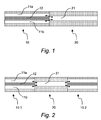
- the invention will be further explained in the following with reference to a device comprising an input optical fiber 10 with two longitudinal holes (fluid channels) 11a and 11b parallel and adjacent the core 12 of the fiber.
- the twin-hole fiber is spliced to a capillary 20 (such as a capillary tubing, a photonic bandgap fiber or a liquid-core, holey fiber), preferably of substantially the same outer diameter as the fiber.
- the arrangement of the optical fiber 10 (and its holes 11a, 11b) and the capillary 20 is such that there is a capability of fluid communication between each of the holes 11a, 11b and the fluid channel 21 of the capillary (indicated by double-head arrows in figures 1 and 2).
- the center of the core 12 of the fiber 10 is axially aligned with at least some portion of the capillary fluid channel 21. Consequently, light can be conveniently coupled from the optical fiber and into the fluid channel of the capillary in a longitudinal, or axial, configuration. Since there is fluid communication between the holes of the fiber and the fluid channel of the capillary, liquid can be likewise conveniently injected into the fluid channel of the capillary.
- a device of this kind is schematically shown in figure 1 of the drawings.
- the device is preferably manufactured by joining the optical fiber 10 and the capillary 20 by means of a standard fiber splicer.
- a standard fiber splicer For example, in the experiments carried out relating to this invention, a fusion splicer of the make Ericsson FSU 975 PM-A was used.
- a current lower than that typically used when splicing standard fibers should preferably be used. The reason for using a lower splicing current in the splicer is that thermal collapse of the fluid channels should be avoided.
- a twin-hole optical fiber 10 was used in connection with a capillary tubing 20.
- the outer cladding diameter of the optical fiber was about 125 ⁇ m.
- Each fluid channel 11a, 11b of the fiber had a diameter of about 25 ⁇ m and a centre to centre separation of about 50 ⁇ m.
- This fiber was spliced to a capillary 20 having similar outer diameter, and a capillary fluid channel 21 having a diameter of about 25 ⁇ m.
- the capillary fluid channel overlapped by margin with both of the fluid channels in the optical fiber, such that there was a capability of fluid communication between the fluid channels of the optical fiber and the capillary tubing.
- the light guiding core of the optical fiber having a diameter of about 8 ⁇ m, was situated approximately midway, symmetrically between the two fluid channels of the fiber.
- the light guiding core was thus axially aligned with the fluid channel of the capillary tubing, such that light could conveniently pass between the light guiding core and the fluid channel of the capillary. Liquid could flow between the fiber holes 11a, 11b and the capillary fluid channel 21 without any formation of bubbles.
- the capillary had a diameter of about 25 ⁇ m and the twin-hole optical fiber had fluid channels of about 34 ⁇ m in diameter, with a centre to centre separation of about 21 ⁇ m. Also in this case, the capillary fluid channel overlapped by margin with both of the fluid channels in the optical fiber, such that there was a capability of fluid communication between the fluid channels of the optical fiber and the capillary tubing.
- FIG. 1 Another embodiment is shown in figure 2.
- a second optical fiber 10.2 in the form of an output fiber in addition to the first optical fiber 10.1, spliced to the capillary 20 in a manner similar to the situation for the first, input fiber.
- light and liquid from the fluid channel of the capillary can be collected at the output fiber for further processing and analysis.
- Figure 3 shows a picture of a twin-hole optical fiber that may be used in the device according to the present invention.
- the two holes (fluid channels) can be seen symmetrically arranged adjacent the light guiding core of the fiber.
- any known principle or device may be used in the analysis of the output light.
- reflective fiber gratings may be used for selectively separating illumination light from fluorescence light emanating from the fiber.
- the capillary can be of virtually any length. However, if very long capillaries are to be used together with a fluid having a refractive index lower than the material of the capillary (e.g. silica, having a refractive index of about 1.45), the inner walls of the fluid channel may be coated with a reflective material, such that light guiding is effected along the capillary in order to reduce loss of light in the process of analysis. Alternatively, when a photonic bandgap fiber or a liquid-core holey fiber is used for the capillary, such reflective coating can be dispensed with since light may be contained in the capillary by the light guiding properties of such fiber itself.
- a fluid having a refractive index lower than the material of the capillary e.g. silica, having a refractive index of about 1.45
- the inner walls of the fluid channel may be coated with a reflective material, such that light guiding is effected along the capillary in order to reduce loss of light in the process of
- gradient index lenses may also be provided at the interface between the optical fiber and the capillary in order to improve the axial coupling of light in to and out from the capillary, thus also providing for a more collimated light beam through the capillary.
- One advantageous feature of the device according to the present invention is that the flow of liquid within the microfluidic device can be controlled optically. Generally, by focusing a high power laser beam onto a capillary, thermal expansion of the liquid inside the capillary can be used in order to intermittently halt or allow the flow of liquid. The following description presupposes that there is a bias pressure applied to the microfluidic system driving liquid through the fluid channels of the device.
- the flow within the capillary is essentially continuous due to the bias pressure applied.
- the illuminated portion of the liquid exhibits thermal expansion effected by the energy deposited by the laser beam.
- This thermal expansion gives a quick push of the liquid at the edge of the heated region in the forward direction, and stops the flow on the opposite side of the heated region thus counteracting the bias pressure applied.
- the laser light is switched off, the opposite takes place, wherein the liquid decreases in volume due to the reduced temperature, causing a quick stop of the flow in the forward direction.
- This principle can be used for controlling the flow of liquid from the two (or more) fluid channels of the optical fiber into the fluid channel of the capillary, or vice versa.
- a device was used wherein liquids of different color were injected into the two fluid channels of the optical fiber.
- a bias pressure was applied to the device, such that the same flow rate was obtained from the two channels of the optical fiber into the fluid channel of the capillary, thus mixing the liquids at the junction between the channels.
- Two laser beams were directed onto the optical fiber, one at each fluid channel therein. The two laser beams were synchronized such that one was switched on when the other was switched off, and vice versa.
- This setup resulted in alternating injection of liquid from the fluid channels of the fiber one at the time, which gave a situation where the liquid inside the fluid channel of the capillary contained discrete portions of differently colored liquids. It should be noted that the dimensions of the capillary are sufficiently small in order for the injected liquid to remain substantially unmixed in the axial direction.
- the same principle can be used for selectively sending the contents of the capillary fluid channel into either of two fluid channels in an output optical fiber.
- particles such as cells flowing in a liquid medium and being marked by fluorescence may be directed into a selected channel of the output fiber depending on, for example, whether a particular tag is detected or not.
- the power and switching periodicity of the illuminating laser beams should be tuned with respect to the bias pressure such that the desired flow control is obtained. If the bias pressure is too high compared to the thermally induced change in flow rate, the flow of liquid will not come to a complete stop during switching, thus resulting in remaining mixture of the two liquids (or poor separation as the case may be).
- a microfluidic device comprising an optical fiber having a light guiding core and at least one fiber fluid channel formed adjacent to the core, and a capillary having a capillary fluid channel.
- the optical fiber and the capillary are spliced to each other such that the center of the light guiding core of the fiber is axially aligned with the capillary fluid channel, while at the same time there is provided a fluid communication between the fiber fluid channels and the capillary fluid channel.
- a convenient and competitive microfluidic device in which fluid and light may be introduced axially into a capillary fluid channel.
- the device can be manufactured by the use of standard splicing techniques, thus making it less costly than prior art devices.
- problems in the prior art relating to comparatively large volumes involved, and to the issue of interfacing the fluid under analysis, are avoided.
- the device according to the invention also provide for optical flow control of a liquid inside the fluid channels, thus facilitating the handling of the liquid and selective sorting of samples.
Landscapes
- Chemical & Material Sciences (AREA)
- Health & Medical Sciences (AREA)
- Physics & Mathematics (AREA)
- Life Sciences & Earth Sciences (AREA)
- General Physics & Mathematics (AREA)
- Analytical Chemistry (AREA)
- General Health & Medical Sciences (AREA)
- Engineering & Computer Science (AREA)
- Immunology (AREA)
- Biochemistry (AREA)
- Chemical Kinetics & Catalysis (AREA)
- Pathology (AREA)
- Molecular Biology (AREA)
- Optics & Photonics (AREA)
- Hematology (AREA)
- Clinical Laboratory Science (AREA)
- Dispersion Chemistry (AREA)
- Mechanical Engineering (AREA)
- General Engineering & Computer Science (AREA)
- Electrochemistry (AREA)
- Optical Couplings Of Light Guides (AREA)
- Optical Measuring Cells (AREA)
- Materials For Photolithography (AREA)
- Mechanical Coupling Of Light Guides (AREA)
Applications Claiming Priority (1)
| Application Number | Priority Date | Filing Date | Title |
|---|---|---|---|
| SE0402609A SE0402609L (sv) | 2004-10-26 | 2004-10-26 | Mikrofluidikanordning |
Publications (3)
| Publication Number | Publication Date |
|---|---|
| EP1653216A2 true EP1653216A2 (fr) | 2006-05-03 |
| EP1653216A3 EP1653216A3 (fr) | 2006-05-31 |
| EP1653216B1 EP1653216B1 (fr) | 2009-11-25 |
Family
ID=33448729
Family Applications (1)
| Application Number | Title | Priority Date | Filing Date |
|---|---|---|---|
| EP05109921A Ceased EP1653216B1 (fr) | 2004-10-26 | 2005-10-24 | Dispositif microfluidique |
Country Status (4)
| Country | Link |
|---|---|
| EP (1) | EP1653216B1 (fr) |
| AT (1) | ATE449958T1 (fr) |
| DE (1) | DE602005017863D1 (fr) |
| SE (1) | SE0402609L (fr) |
Cited By (11)
| Publication number | Priority date | Publication date | Assignee | Title |
|---|---|---|---|---|
| WO2008061949A1 (fr) * | 2006-11-22 | 2008-05-29 | Siemens Aktiengesellschaft | Cellule de mesure optique et appareil de contrôle de gaz |
| US7595882B1 (en) | 2008-04-14 | 2009-09-29 | Geneal Electric Company | Hollow-core waveguide-based raman systems and methods |
| EP2735860A1 (fr) | 2012-11-21 | 2014-05-28 | Acreo Swedish ICT AB | Dispositif optofluidique |
| TWI619931B (zh) * | 2013-01-22 | 2018-04-01 | 國立高雄應用科技大學 | 光纖感測器裝配方法及其構造 |
| CN109211839A (zh) * | 2018-09-01 | 2019-01-15 | 哈尔滨工程大学 | 一种双通道边孔光纤光栅传感装置 |
| CN111617683A (zh) * | 2020-04-10 | 2020-09-04 | 桂林电子科技大学 | 基于多孔光纤的光热微流混合器 |
| CN111637034A (zh) * | 2020-04-10 | 2020-09-08 | 桂林电子科技大学 | 基于环形芯毛细管光纤的光热微推进器 |
| CN111637031A (zh) * | 2020-04-10 | 2020-09-08 | 桂林电子科技大学 | 基于多孔光纤的光热助推器 |
| CN111632534A (zh) * | 2020-04-10 | 2020-09-08 | 桂林电子科技大学 | 基于单孔光纤的光热微流混合器 |
| CN113607689A (zh) * | 2021-07-08 | 2021-11-05 | 天津工业大学 | 一种基于双孔微结构光纤的法布里-珀罗微流腔传感器 |
| CN113866127A (zh) * | 2021-10-26 | 2021-12-31 | 天津工业大学 | 一种基于四孔微结构光纤集成的纤内微流控传感器件 |
Families Citing this family (1)
| Publication number | Priority date | Publication date | Assignee | Title |
|---|---|---|---|---|
| US20240310599A1 (en) * | 2023-03-14 | 2024-09-19 | Raytheon Technologies Corporation | Coupling optical fibers and fluid passages |
Family Cites Families (4)
| Publication number | Priority date | Publication date | Assignee | Title |
|---|---|---|---|---|
| US6343174B1 (en) * | 1999-07-30 | 2002-01-29 | Ceramoptec Industries, Inc. | Laser delivery system with optical fibers having fluid delivery channels |
| US6850657B2 (en) * | 2002-02-08 | 2005-02-01 | The Research Foundation Of State University Of New York | Capillary waveguide fluorescence sensor |
| GB0214545D0 (en) * | 2002-06-24 | 2002-08-07 | Blazephotonics Ltd | Fluid analysis |
| JP2005538287A (ja) * | 2002-08-15 | 2005-12-15 | エムイーエムエスフロー・アンパルトセルスカブ | マイクロ液体処理装置とその使用方法 |
-
2004
- 2004-10-26 SE SE0402609A patent/SE0402609L/xx unknown
-
2005
- 2005-10-24 AT AT05109921T patent/ATE449958T1/de not_active IP Right Cessation
- 2005-10-24 EP EP05109921A patent/EP1653216B1/fr not_active Ceased
- 2005-10-24 DE DE602005017863T patent/DE602005017863D1/de not_active Expired - Lifetime
Cited By (14)
| Publication number | Priority date | Publication date | Assignee | Title |
|---|---|---|---|---|
| WO2008061949A1 (fr) * | 2006-11-22 | 2008-05-29 | Siemens Aktiengesellschaft | Cellule de mesure optique et appareil de contrôle de gaz |
| US8570520B2 (en) | 2006-11-22 | 2013-10-29 | Siemens Aktiengesellschaft | Optical measuring cell and gas monitor |
| US7595882B1 (en) | 2008-04-14 | 2009-09-29 | Geneal Electric Company | Hollow-core waveguide-based raman systems and methods |
| EP2735860A1 (fr) | 2012-11-21 | 2014-05-28 | Acreo Swedish ICT AB | Dispositif optofluidique |
| TWI619931B (zh) * | 2013-01-22 | 2018-04-01 | 國立高雄應用科技大學 | 光纖感測器裝配方法及其構造 |
| CN109211839A (zh) * | 2018-09-01 | 2019-01-15 | 哈尔滨工程大学 | 一种双通道边孔光纤光栅传感装置 |
| CN111617683A (zh) * | 2020-04-10 | 2020-09-04 | 桂林电子科技大学 | 基于多孔光纤的光热微流混合器 |
| CN111637034A (zh) * | 2020-04-10 | 2020-09-08 | 桂林电子科技大学 | 基于环形芯毛细管光纤的光热微推进器 |
| CN111637031A (zh) * | 2020-04-10 | 2020-09-08 | 桂林电子科技大学 | 基于多孔光纤的光热助推器 |
| CN111632534A (zh) * | 2020-04-10 | 2020-09-08 | 桂林电子科技大学 | 基于单孔光纤的光热微流混合器 |
| CN113607689A (zh) * | 2021-07-08 | 2021-11-05 | 天津工业大学 | 一种基于双孔微结构光纤的法布里-珀罗微流腔传感器 |
| CN113607689B (zh) * | 2021-07-08 | 2024-04-09 | 天津工业大学 | 一种基于双孔微结构光纤的法布里-珀罗微流腔传感器 |
| CN113866127A (zh) * | 2021-10-26 | 2021-12-31 | 天津工业大学 | 一种基于四孔微结构光纤集成的纤内微流控传感器件 |
| CN113866127B (zh) * | 2021-10-26 | 2024-01-16 | 天津工业大学 | 一种基于四孔微结构光纤集成的纤内微流控传感器件 |
Also Published As
| Publication number | Publication date |
|---|---|
| EP1653216A3 (fr) | 2006-05-31 |
| EP1653216B1 (fr) | 2009-11-25 |
| ATE449958T1 (de) | 2009-12-15 |
| SE527483C2 (sv) | 2006-03-21 |
| SE0402609L (sv) | 2006-03-21 |
| SE0402609D0 (sv) | 2004-10-26 |
| DE602005017863D1 (de) | 2010-01-07 |
Similar Documents
| Publication | Publication Date | Title |
|---|---|---|
| Bellini et al. | Femtosecond laser fabricated monolithic chip for optical trapping and stretching of single cells | |
| EP1653216B1 (fr) | Dispositif microfluidique | |
| Mogensen et al. | Integration of polymer waveguides for optical detection in microfabricated chemical analysis systems | |
| Konorov et al. | Photonic-crystal fiber as a multifunctional optical sensor and sample collector | |
| US8552363B2 (en) | System and method for optically driven separations using fluid filled core optical fibers | |
| Yin et al. | Integrated optical waveguides with liquid cores | |
| Wolfe et al. | Diffusion-controlled optical elements for optofluidics | |
| US8398935B2 (en) | Sheath flow device and method | |
| CA2841430C (fr) | Injection de plusieurs volumes dans et hors de gouttelettes | |
| US8651138B2 (en) | Tubular array for fluidic focusing with integrated optical access region | |
| Ruano et al. | Design and fabrication of a silica on silicon integrated optical biochip as a fluorescence microarray platform | |
| US9067204B2 (en) | Sheath flow device and method | |
| Mandal et al. | Optofluidic transport in liquid core waveguiding structures | |
| WO2007021815A2 (fr) | Appareils, systemes et procedes a puce microfluidique possedant des interconnexions fluidiques et a fibres optiques | |
| US20150212279A1 (en) | Optical device having liquid-core optical fibre and method for producing such a device | |
| Sudirman et al. | All-fiber optofluidic component to combine light and fluid | |
| Bar-David et al. | Cavity optofluidics: a μdroplet’s whispering-gallery mode makes a μvortex | |
| Blakely et al. | Flow-dependent optofluidic particle trapping and circulation | |
| Zhang et al. | Remarks of Optical Fibers and Devices for Microfluidic Sensing: Preparation and Processing | |
| WO2006015360A1 (fr) | Guides d'ondes fluides et utilisations | |
| Wu et al. | Side-hole microstructured optical fiber integrative twin-microchannels for optofluidic sensing | |
| Lee et al. | Versatile optofluidic ring resonator lasers based on microdroplets | |
| EP2735860B1 (fr) | Dispositif optofluidique | |
| Whitesides et al. | Fluidic optics | |
| Awerkamp et al. | 3D printed mounts for microdroplet resonators |
Legal Events
| Date | Code | Title | Description |
|---|---|---|---|
| PUAI | Public reference made under article 153(3) epc to a published international application that has entered the european phase |
Free format text: ORIGINAL CODE: 0009012 |
|
| PUAL | Search report despatched |
Free format text: ORIGINAL CODE: 0009013 |
|
| AK | Designated contracting states |
Kind code of ref document: A2 Designated state(s): AT BE BG CH CY CZ DE DK EE ES FI FR GB GR HU IE IS IT LI LT LU LV MC NL PL PT RO SE SI SK TR |
|
| AX | Request for extension of the european patent |
Extension state: AL BA HR MK YU |
|
| AK | Designated contracting states |
Kind code of ref document: A3 Designated state(s): AT BE BG CH CY CZ DE DK EE ES FI FR GB GR HU IE IS IT LI LT LU LV MC NL PL PT RO SE SI SK TR |
|
| AX | Request for extension of the european patent |
Extension state: AL BA HR MK YU |
|
| 17P | Request for examination filed |
Effective date: 20061130 |
|
| 17Q | First examination report despatched |
Effective date: 20070104 |
|
| AKX | Designation fees paid |
Designated state(s): AT BE BG CH CY CZ DE DK EE ES FI FR GB GR HU IE IS IT LI LT LU LV MC NL PL PT RO SE SI SK TR |
|
| GRAP | Despatch of communication of intention to grant a patent |
Free format text: ORIGINAL CODE: EPIDOSNIGR1 |
|
| GRAS | Grant fee paid |
Free format text: ORIGINAL CODE: EPIDOSNIGR3 |
|
| GRAA | (expected) grant |
Free format text: ORIGINAL CODE: 0009210 |
|
| AK | Designated contracting states |
Kind code of ref document: B1 Designated state(s): AT BE BG CH CY CZ DE DK EE ES FI FR GB GR HU IE IS IT LI LT LU LV MC NL PL PT RO SE SI SK TR |
|
| REG | Reference to a national code |
Ref country code: GB Ref legal event code: FG4D |
|
| REG | Reference to a national code |
Ref country code: CH Ref legal event code: EP |
|
| REG | Reference to a national code |
Ref country code: IE Ref legal event code: FG4D |
|
| REF | Corresponds to: |
Ref document number: 602005017863 Country of ref document: DE Date of ref document: 20100107 Kind code of ref document: P |
|
| REG | Reference to a national code |
Ref country code: NL Ref legal event code: VDEP Effective date: 20091125 |
|
| LTIE | Lt: invalidation of european patent or patent extension |
Effective date: 20091125 |
|
| PG25 | Lapsed in a contracting state [announced via postgrant information from national office to epo] |
Ref country code: LT Free format text: LAPSE BECAUSE OF FAILURE TO SUBMIT A TRANSLATION OF THE DESCRIPTION OR TO PAY THE FEE WITHIN THE PRESCRIBED TIME-LIMIT Effective date: 20091125 Ref country code: FI Free format text: LAPSE BECAUSE OF FAILURE TO SUBMIT A TRANSLATION OF THE DESCRIPTION OR TO PAY THE FEE WITHIN THE PRESCRIBED TIME-LIMIT Effective date: 20091125 Ref country code: PT Free format text: LAPSE BECAUSE OF FAILURE TO SUBMIT A TRANSLATION OF THE DESCRIPTION OR TO PAY THE FEE WITHIN THE PRESCRIBED TIME-LIMIT Effective date: 20100325 Ref country code: IS Free format text: LAPSE BECAUSE OF FAILURE TO SUBMIT A TRANSLATION OF THE DESCRIPTION OR TO PAY THE FEE WITHIN THE PRESCRIBED TIME-LIMIT Effective date: 20100325 Ref country code: SE Free format text: LAPSE BECAUSE OF FAILURE TO SUBMIT A TRANSLATION OF THE DESCRIPTION OR TO PAY THE FEE WITHIN THE PRESCRIBED TIME-LIMIT Effective date: 20091125 |
|
| PG25 | Lapsed in a contracting state [announced via postgrant information from national office to epo] |
Ref country code: SI Free format text: LAPSE BECAUSE OF FAILURE TO SUBMIT A TRANSLATION OF THE DESCRIPTION OR TO PAY THE FEE WITHIN THE PRESCRIBED TIME-LIMIT Effective date: 20091125 Ref country code: PL Free format text: LAPSE BECAUSE OF FAILURE TO SUBMIT A TRANSLATION OF THE DESCRIPTION OR TO PAY THE FEE WITHIN THE PRESCRIBED TIME-LIMIT Effective date: 20091125 Ref country code: LV Free format text: LAPSE BECAUSE OF FAILURE TO SUBMIT A TRANSLATION OF THE DESCRIPTION OR TO PAY THE FEE WITHIN THE PRESCRIBED TIME-LIMIT Effective date: 20091125 Ref country code: CY Free format text: LAPSE BECAUSE OF FAILURE TO SUBMIT A TRANSLATION OF THE DESCRIPTION OR TO PAY THE FEE WITHIN THE PRESCRIBED TIME-LIMIT Effective date: 20091125 |
|
| PG25 | Lapsed in a contracting state [announced via postgrant information from national office to epo] |
Ref country code: AT Free format text: LAPSE BECAUSE OF FAILURE TO SUBMIT A TRANSLATION OF THE DESCRIPTION OR TO PAY THE FEE WITHIN THE PRESCRIBED TIME-LIMIT Effective date: 20091125 Ref country code: BE Free format text: LAPSE BECAUSE OF FAILURE TO SUBMIT A TRANSLATION OF THE DESCRIPTION OR TO PAY THE FEE WITHIN THE PRESCRIBED TIME-LIMIT Effective date: 20091125 |
|
| PG25 | Lapsed in a contracting state [announced via postgrant information from national office to epo] |
Ref country code: NL Free format text: LAPSE BECAUSE OF FAILURE TO SUBMIT A TRANSLATION OF THE DESCRIPTION OR TO PAY THE FEE WITHIN THE PRESCRIBED TIME-LIMIT Effective date: 20091125 Ref country code: ES Free format text: LAPSE BECAUSE OF FAILURE TO SUBMIT A TRANSLATION OF THE DESCRIPTION OR TO PAY THE FEE WITHIN THE PRESCRIBED TIME-LIMIT Effective date: 20100308 Ref country code: EE Free format text: LAPSE BECAUSE OF FAILURE TO SUBMIT A TRANSLATION OF THE DESCRIPTION OR TO PAY THE FEE WITHIN THE PRESCRIBED TIME-LIMIT Effective date: 20091125 Ref country code: DK Free format text: LAPSE BECAUSE OF FAILURE TO SUBMIT A TRANSLATION OF THE DESCRIPTION OR TO PAY THE FEE WITHIN THE PRESCRIBED TIME-LIMIT Effective date: 20091125 Ref country code: BG Free format text: LAPSE BECAUSE OF FAILURE TO SUBMIT A TRANSLATION OF THE DESCRIPTION OR TO PAY THE FEE WITHIN THE PRESCRIBED TIME-LIMIT Effective date: 20100225 Ref country code: RO Free format text: LAPSE BECAUSE OF FAILURE TO SUBMIT A TRANSLATION OF THE DESCRIPTION OR TO PAY THE FEE WITHIN THE PRESCRIBED TIME-LIMIT Effective date: 20091125 |
|
| PG25 | Lapsed in a contracting state [announced via postgrant information from national office to epo] |
Ref country code: CZ Free format text: LAPSE BECAUSE OF FAILURE TO SUBMIT A TRANSLATION OF THE DESCRIPTION OR TO PAY THE FEE WITHIN THE PRESCRIBED TIME-LIMIT Effective date: 20091125 Ref country code: SK Free format text: LAPSE BECAUSE OF FAILURE TO SUBMIT A TRANSLATION OF THE DESCRIPTION OR TO PAY THE FEE WITHIN THE PRESCRIBED TIME-LIMIT Effective date: 20091125 |
|
| PLBE | No opposition filed within time limit |
Free format text: ORIGINAL CODE: 0009261 |
|
| STAA | Information on the status of an ep patent application or granted ep patent |
Free format text: STATUS: NO OPPOSITION FILED WITHIN TIME LIMIT |
|
| PG25 | Lapsed in a contracting state [announced via postgrant information from national office to epo] |
Ref country code: GR Free format text: LAPSE BECAUSE OF FAILURE TO SUBMIT A TRANSLATION OF THE DESCRIPTION OR TO PAY THE FEE WITHIN THE PRESCRIBED TIME-LIMIT Effective date: 20100226 |
|
| 26N | No opposition filed |
Effective date: 20100826 |
|
| PG25 | Lapsed in a contracting state [announced via postgrant information from national office to epo] |
Ref country code: IT Free format text: LAPSE BECAUSE OF FAILURE TO SUBMIT A TRANSLATION OF THE DESCRIPTION OR TO PAY THE FEE WITHIN THE PRESCRIBED TIME-LIMIT Effective date: 20091125 |
|
| PG25 | Lapsed in a contracting state [announced via postgrant information from national office to epo] |
Ref country code: MC Free format text: LAPSE BECAUSE OF NON-PAYMENT OF DUE FEES Effective date: 20101031 |
|
| REG | Reference to a national code |
Ref country code: CH Ref legal event code: PL |
|
| PG25 | Lapsed in a contracting state [announced via postgrant information from national office to epo] |
Ref country code: LI Free format text: LAPSE BECAUSE OF NON-PAYMENT OF DUE FEES Effective date: 20101031 Ref country code: CH Free format text: LAPSE BECAUSE OF NON-PAYMENT OF DUE FEES Effective date: 20101031 |
|
| PG25 | Lapsed in a contracting state [announced via postgrant information from national office to epo] |
Ref country code: IE Free format text: LAPSE BECAUSE OF NON-PAYMENT OF DUE FEES Effective date: 20101024 |
|
| PG25 | Lapsed in a contracting state [announced via postgrant information from national office to epo] |
Ref country code: HU Free format text: LAPSE BECAUSE OF FAILURE TO SUBMIT A TRANSLATION OF THE DESCRIPTION OR TO PAY THE FEE WITHIN THE PRESCRIBED TIME-LIMIT Effective date: 20100526 Ref country code: LU Free format text: LAPSE BECAUSE OF NON-PAYMENT OF DUE FEES Effective date: 20101024 |
|
| PG25 | Lapsed in a contracting state [announced via postgrant information from national office to epo] |
Ref country code: TR Free format text: LAPSE BECAUSE OF FAILURE TO SUBMIT A TRANSLATION OF THE DESCRIPTION OR TO PAY THE FEE WITHIN THE PRESCRIBED TIME-LIMIT Effective date: 20091125 |
|
| REG | Reference to a national code |
Ref country code: FR Ref legal event code: PLFP Year of fee payment: 11 |
|
| REG | Reference to a national code |
Ref country code: FR Ref legal event code: PLFP Year of fee payment: 12 |
|
| REG | Reference to a national code |
Ref country code: FR Ref legal event code: PLFP Year of fee payment: 13 |
|
| REG | Reference to a national code |
Ref country code: FR Ref legal event code: PLFP Year of fee payment: 14 |
|
| PGFP | Annual fee paid to national office [announced via postgrant information from national office to epo] |
Ref country code: GB Payment date: 20220915 Year of fee payment: 18 |
|
| PGFP | Annual fee paid to national office [announced via postgrant information from national office to epo] |
Ref country code: FR Payment date: 20220916 Year of fee payment: 18 |
|
| PGFP | Annual fee paid to national office [announced via postgrant information from national office to epo] |
Ref country code: DE Payment date: 20220921 Year of fee payment: 18 |
|
| REG | Reference to a national code |
Ref country code: DE Ref legal event code: R119 Ref document number: 602005017863 Country of ref document: DE |
|
| GBPC | Gb: european patent ceased through non-payment of renewal fee |
Effective date: 20231024 |
|
| PG25 | Lapsed in a contracting state [announced via postgrant information from national office to epo] |
Ref country code: GB Free format text: LAPSE BECAUSE OF NON-PAYMENT OF DUE FEES Effective date: 20231024 |
|
| PG25 | Lapsed in a contracting state [announced via postgrant information from national office to epo] |
Ref country code: GB Free format text: LAPSE BECAUSE OF NON-PAYMENT OF DUE FEES Effective date: 20231024 Ref country code: FR Free format text: LAPSE BECAUSE OF NON-PAYMENT OF DUE FEES Effective date: 20231031 Ref country code: DE Free format text: LAPSE BECAUSE OF NON-PAYMENT OF DUE FEES Effective date: 20240501 |